CN217348487U - Automatic packing and boxing equipment for cylindrical batteries - Google Patents
Automatic packing and boxing equipment for cylindrical batteries Download PDFInfo
- Publication number
- CN217348487U CN217348487U CN202220082880.1U CN202220082880U CN217348487U CN 217348487 U CN217348487 U CN 217348487U CN 202220082880 U CN202220082880 U CN 202220082880U CN 217348487 U CN217348487 U CN 217348487U
- Authority
- CN
- China
- Prior art keywords
- fixedly connected
- plate
- cylinder
- bearing plate
- fixing seat
- Prior art date
- Legal status (The legal status is an assumption and is not a legal conclusion. Google has not performed a legal analysis and makes no representation as to the accuracy of the status listed.)
- Expired - Fee Related
Links
Images


Classifications
-
- Y—GENERAL TAGGING OF NEW TECHNOLOGICAL DEVELOPMENTS; GENERAL TAGGING OF CROSS-SECTIONAL TECHNOLOGIES SPANNING OVER SEVERAL SECTIONS OF THE IPC; TECHNICAL SUBJECTS COVERED BY FORMER USPC CROSS-REFERENCE ART COLLECTIONS [XRACs] AND DIGESTS
- Y02—TECHNOLOGIES OR APPLICATIONS FOR MITIGATION OR ADAPTATION AGAINST CLIMATE CHANGE
- Y02P—CLIMATE CHANGE MITIGATION TECHNOLOGIES IN THE PRODUCTION OR PROCESSING OF GOODS
- Y02P70/00—Climate change mitigation technologies in the production process for final industrial or consumer products
- Y02P70/50—Manufacturing or production processes characterised by the final manufactured product
Landscapes
- Battery Mounting, Suspending (AREA)
Abstract
本实用新型涉及自动入盒技术领域,尤其为圆柱类电池自动化包装入盒设备,包括第一固定座,所述第一固定座的右侧固定连接有第一气缸,所述第一气缸的输出端固定连接有连接板,所述连接板的顶部固定连接有承重板,所述承重板底部的两侧均设置有第一导轨,所述第一导轨的顶部滑动连接有第一滑块,所述第一滑块的顶部与承重板固定连接。本实用新型具备便于上料的优点,在实际使用过程中,通过纸板抓取组件的设置,可根据实际情况对包装盒内部空间的大小进行改变,方便电池在盒中进行整齐的摆放,有利于对电池进行保护,避免了纸盒损坏和浪费原材料的情况,取代了人工,解放了生产力,提高了中小型企业的发展。
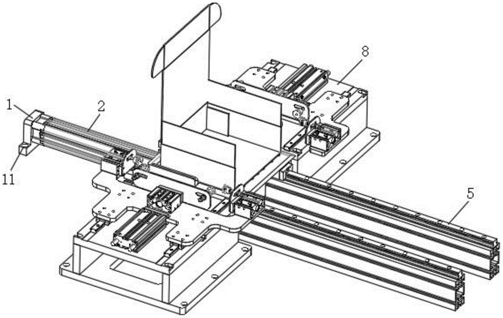
The utility model relates to the technical field of automatic boxing, in particular to an automatic packaging and boxing device for cylindrical batteries, comprising a first fixing seat, a first cylinder is fixedly connected to the right side of the first fixing seat, and an output The end is fixedly connected with a connecting plate, the top of the connecting plate is fixedly connected with a bearing plate, both sides of the bottom of the bearing plate are provided with a first guide rail, and the top of the first guide rail is slidably connected with a first slider, so The top of the first sliding block is fixedly connected with the bearing plate. The utility model has the advantage of being convenient for feeding materials. In the actual use process, the size of the inner space of the packaging box can be changed according to the actual situation through the setting of the cardboard grabbing component, which is convenient for the batteries to be neatly placed in the box. It is beneficial to protect the battery, avoid the damage of the carton and the waste of raw materials, replace the labor, liberate the productivity, and improve the development of small and medium-sized enterprises.
Description
技术领域technical field
本实用新型涉及自动入盒技术领域,具体为圆柱类电池自动化包装入盒设备。The utility model relates to the technical field of automatic boxing, in particular to an automatic packaging and boxing device for cylindrical batteries.
背景技术Background technique
电池指盛有电解质溶液和金属电极以产生电流的杯、槽或其他容器或复合容器的部分空间,能将化学能转化成电能的装置,随着科技的进步,使得电池的用途逐渐变广,从而研发出几种不同形状的电池适应于不同的领域,其中圆柱类形状电池的用途最为广阔和重要。A battery refers to a part of the space of a cup, tank or other container or composite container that contains an electrolyte solution and metal electrodes to generate electric current, a device that can convert chemical energy into electrical energy. With the advancement of technology, the use of batteries has gradually become wider. As a result, several different shapes of batteries have been developed to adapt to different fields. Among them, the use of cylindrical batteries is the most extensive and important.
圆柱类电池在加工中需要特定的纸盒进行包装,传统的包装入盒是由人工完成的,入盒效率低,且容易出现漏装现象,在现有的电池包装领域,需要使用到包装入盒设备,现有的入盒设备不能调整盒体的空间大小,导致机械手不能精准入盒,降低了包装入盒设备实用性,为了保证机械手能够准确将电池送入包装盒内,一种为圆柱类电池自动化包装入盒设备,亟待开发。Cylindrical batteries need a specific carton for packaging during processing. The traditional packaging into the box is done manually, the efficiency of the box is low, and the phenomenon of missing packaging is easy to occur. In the existing battery packaging field, it is necessary to use the packaging into the box. Box equipment, the existing boxing equipment cannot adjust the space size of the box body, which leads to the inability of the manipulator to accurately enter the box, which reduces the practicability of the packaging and boxing equipment. In order to ensure that the manipulator can accurately send the battery into the box, a cylindrical Battery-like automatic packaging and boxing equipment is in urgent need of development.
实用新型内容Utility model content
本实用新型的目的在于提供圆柱类电池自动化包装入盒设备,具备便于上料的优点,解决了上述背景技术提出的问题。The purpose of the present utility model is to provide an automatic packaging and boxing device for cylindrical batteries, which has the advantage of being convenient for feeding, and solves the problems raised by the above-mentioned background technology.
为达成上述目的,本实用新型提供如下技术方案:圆柱类电池自动化包装入盒设备,包括第一固定座,所述第一固定座的右侧固定连接有第一气缸,所述第一气缸的输出端固定连接有连接板,所述连接板的顶部固定连接有承重板,所述承重板底部的两侧均设置有第一导轨,所述第一导轨的顶部滑动连接有第一滑块,所述第一滑块的顶部与承重板固定连接,两个第一导轨的一侧均设置有纸板抓取组件。In order to achieve the above purpose, the present invention provides the following technical solutions: a cylindrical battery is automatically packaged into a box, including a first fixing seat, a first cylinder is fixedly connected to the right side of the first fixing seat, and the first cylinder is The output end is fixedly connected with a connecting plate, the top of the connecting plate is fixedly connected with a load-bearing plate, both sides of the bottom of the load-bearing plate are provided with first guide rails, and the top of the first guide rail is slidably connected with a first slider, The top of the first sliding block is fixedly connected with the bearing plate, and one side of the two first guide rails is provided with a cardboard grabbing assembly.
进一步的,所述纸板抓取组件包含有位于第一导轨一侧的安装板,所述安装板顶部的两侧均固定连接有支撑板,所述支撑板的顶部固定连接有固定板,所述固定板的高度与承重板的高度位于同一轴线上,所述固定板的顶部固定连接有第二气缸,所述固定板的顶部设置有运行板,所述运行板的一侧开设有通槽,所述通槽的内腔固定连接有第一推压板,所述第二气缸的输出端延伸至通槽的内腔并与第一推压板固定连接,所述运行板的顶部固定连接有第三气缸,所述第三气缸的输出端固定连接有第二推压板,所述第二推压板的一侧开设有两个安装槽一,所述安装槽一的内腔滑动连接有安装槽二,所述安装槽二的一端固定连接有吸盘,所述运行板的两侧均固定连接有吸取模组。Further, the cardboard grabbing assembly includes a mounting plate located on one side of the first guide rail, a support plate is fixedly connected to both sides of the top of the mounting plate, and a fixing plate is fixedly connected to the top of the support plate. The height of the fixed plate and the height of the bearing plate are located on the same axis, the top of the fixed plate is fixedly connected with the second cylinder, the top of the fixed plate is provided with a running plate, and one side of the running plate is provided with a through slot, The inner cavity of the through groove is fixedly connected with a first pushing plate, the output end of the second cylinder extends to the inner cavity of the through groove and is fixedly connected with the first pushing plate, and the top of the running plate is fixedly connected with a third pushing plate. A cylinder, the output end of the third cylinder is fixedly connected with a second push plate, one side of the second push plate is provided with two installation grooves 1, the inner cavity of the installation groove 1 is slidably connected with the
进一步的,作为本实用新型一种优选的,所述固定板顶部的两侧均开设有放置槽,所述放置槽的内腔固定连接有第二运输模组,所述第二运输模组的顶部与运行板固定连接。Further, as a preferred option of the present invention, both sides of the top of the fixing plate are provided with placement slots, and the inner cavity of the placement slot is fixedly connected with a second transport module, and the second transport module is The top is fixedly connected to the running board.
进一步的,作为本实用新型一种优选的,所述运行板的一侧固定连接有三个固定杆,所述固定杆的一端固定连接有限位块。Further, as a preferred embodiment of the present invention, one side of the running plate is fixedly connected with three fixing rods, and one end of the fixing rods is fixedly connected with a limit block.
进一步的,作为本实用新型一种优选的,所述承重板的底部固定连接有第二固定座,所述第二固定座的内腔与第一气缸的输出轴固定连接。Further, as a preferred option of the present invention, the bottom of the bearing plate is fixedly connected with a second fixing seat, and the inner cavity of the second fixing seat is fixedly connected with the output shaft of the first cylinder.
进一步的,作为本实用新型一种优选的,所述承重板顶部的左侧固定连接有导向块,所述导向块的形状为L形。Further, as a preferred option of the present invention, a guide block is fixedly connected to the left side of the top of the load-bearing plate, and the shape of the guide block is L-shape.
进一步的,作为本实用新型一种优选的,所述安装板顶部的两侧均开设有若干第一安装孔,所述第一固定座的两侧均开设有若干个第二安装孔。Further, as a preferred option of the present invention, both sides of the top of the mounting plate are provided with a number of first mounting holes, and both sides of the first fixing seat are provided with a number of second mounting holes.
有益效果,本申请的技术方案具备如下技术效果:本实用新型通过把圆柱类电池包装盒放置到承重板上,再利用四周的纸板抓取组件对存放盒的四周进行吸触,从而利用纸板抓取组件的吸力对存放盒进行撑开,当撑开后,使用者再把电池放置到存放盒中,第一气缸的输出端推动连接板向右移动,再利用连接板带动承重板通过第一滑块在第一导轨中向右滑动,再利用承重板带动存放盒向右移动,最后带动存放盒以及内部的电池一起向下一工位进行移动和加工,在实际使用过程中,通过纸板抓取组件的设置,可根据实际情况对包装盒内部空间的大小进行改变,方便电池在盒中进行整齐的摆放,有利于对电池进行保护,避免了纸盒损坏和浪费原材料的情况,取代了人工,解放了生产力,提高了中小型企业的发展,解决了传现有的电池包装领域,需要使用到包装入盒设备,现有的入盒设备不能调整盒体的空间大小,导致机械手不能精准入盒,降低了包装入盒设备实用性的问题。Beneficial effects, the technical solution of the present application has the following technical effects: the utility model places the cylindrical battery packaging box on the load-bearing plate, and then uses the cardboard grabbing components around it to suck and touch the surrounding of the storage box, thereby using the cardboard to grab The suction force of the assembly is used to open the storage box. After the expansion is completed, the user places the battery in the storage box, and the output end of the first cylinder pushes the connecting plate to move to the right, and then uses the connecting plate to drive the load-bearing plate to pass through the first cylinder. The slider slides to the right in the first guide rail, and then uses the load-bearing plate to drive the storage box to move to the right, and finally drives the storage box and the internal battery to move and process to the next station together. By taking the settings of the components, the size of the internal space of the packaging box can be changed according to the actual situation, which is convenient for the neat placement of the battery in the box, which is conducive to the protection of the battery, and avoids the damage of the carton and the waste of raw materials. Labor, liberates productivity, improves the development of small and medium-sized enterprises, and solves the need to use packaging and boxing equipment in the existing battery packaging field. The existing boxing equipment cannot adjust the space of the box body, resulting in the inaccuracy of the manipulator. Into the box, reducing the practicability of the packaging and boxing equipment.
应当理解,前述构思以及在下面更加详细地描述的额外构思的所有组合只要在这样的构思不相互矛盾的情况下都可以被视为本公开的实用新型主题的一部分。It should be understood that all combinations of the foregoing concepts, as well as additional concepts described in greater detail below, are also considered part of the inventive subject matter of the present disclosure, provided that such concepts are not mutually inconsistent.
附图说明Description of drawings
附图用来提供对本实用新型的进一步理解,并且构成说明书的一部分,与本实用新型的实施例一起用于解释本实用新型,并不构成对本实用新型的限制。在附图中:The accompanying drawings are used to provide a further understanding of the present invention, and constitute a part of the specification, and are used to explain the present invention together with the embodiments of the present invention, and do not constitute a limitation to the present invention. In the attached image:
图1为本实用新型结构示意图;Fig. 1 is the structural representation of the utility model;
图2为本实用新型部分结构立体示意图一;Fig. 2 is a schematic three-dimensional schematic diagram of a part of the structure of the present utility model;
图3为本实用新型仰视图;Fig. 3 is the bottom view of the utility model;
图4为本实用新型部分结构立体示意图二;FIG. 4 is a second schematic perspective view of the partial structure of the present utility model;
图5为本实用新型纸板抓取组件的侧视图;Figure 5 is a side view of the cardboard grabbing assembly of the present invention;
图6为本实用新型纸板抓取组件的俯视图;6 is a top view of the cardboard grabbing assembly of the present invention;
图7为本实用新型图2中A的局部放大图;Fig. 7 is a partial enlarged view of A in Fig. 2 of the utility model;
图8为本实用新型图3中B的局部放大图;Fig. 8 is the partial enlarged view of B in Fig. 3 of the utility model;
图9为本实用新型图4中C的局部放大图。FIG. 9 is a partial enlarged view of C in FIG. 4 of the present utility model.
图中,各附图标记的含义如下:1、第一固定座;2、第一气缸; 3、连接板;4、承重板;5、第一导轨;6、第一滑块;7、第一安装孔;8、纸板抓取组件;801、安装板;802、支撑板;803、固定板; 804、第二气缸;805、运行板;806、通槽;807、第一推压板;808、第三气缸;809、第二推压板;810、安装槽一;811、安装槽二;812、吸盘;813、吸取模组;9、放置槽;10、第二运输模组;11、第二安装孔;12、固定杆;13、限位块;14、第二固定座;15、导向块。In the figure, the meanings of the reference signs are as follows: 1. The first fixing seat; 2. The first cylinder; 3. The connecting plate; 4. The bearing plate; 5. The first guide rail; 6. The first sliding block; 1. Mounting hole; 8. Cardboard grab assembly; 801, Mounting plate; 802, Support plate; 803, Fixing plate; 804, Second cylinder; 805, Running plate; 806, Through groove; , the third cylinder; 809, the second push plate; 810, the installation slot one; 811, the installation slot two; 812, the suction cup; 813, the suction module; 9, the placement slot; 10, the second transport module; 2. Mounting holes; 12. Fixing rod; 13. Limiting block; 14. Second fixing seat; 15. Guide block.
具体实施方式Detailed ways
下面将结合本实用新型实施例中的附图,对本实用新型实施例中的技术方案进行清楚、完整地描述,为了更了解本实用新型的技术内容,特举具体实施例并配合所附图式说明如下。在本公开中参照附图来描述本实用新型的各方面,附图中示出了许多说明的实施例。应当理解,上面介绍的多种构思和实施例,以及下面更加详细地描述的那些构思和实施方式可以以很多方式中任意一种来实施。基于本实用新型中的实施例,本领域普通技术人员在没有做出创造性劳动前提下所获得的所有其他实施例,都属于本实用新型保护的范围。The technical solutions in the embodiments of the present utility model will be described clearly and completely below in conjunction with the accompanying drawings in the embodiments of the present utility model. described as follows. Aspects of the invention are described in this disclosure with reference to the accompanying drawings, in which a number of illustrative embodiments are shown. It should be understood that the various concepts and embodiments presented above, as well as those concepts and implementations described in greater detail below, can be implemented in any of numerous ways. Based on the embodiments of the present invention, all other embodiments obtained by those of ordinary skill in the art without creative work fall within the protection scope of the present invention.
如附图1至附图9所示:本实施例提供圆柱类电池自动化包装入盒设备,包括第一固定座1,第一固定座1的右侧固定连接有第一气缸2,第一气缸2的输出端固定连接有连接板3,连接板3的顶部固定连接有承重板4,承重板4顶部的左侧固定连接有导向块15,导向块15的形状为L形,承重板4底部的两侧均设置有第一导轨5,第一导轨5的顶部滑动连接有第一滑块6,第一滑块6的顶部与承重板 4固定连接,两个第一导轨5的一侧均设置有纸板抓取组件8,纸板抓取组件8包含有位于第一导轨5一侧的安装板801,安装板801顶部的两侧均开设有若干第一安装孔7,第一固定座1的两侧均开设有若干个第二安装孔11,安装板801顶部的两侧均固定连接有支撑板 802,支撑板802的顶部固定连接有固定板803,固定板803的高度与承重板4的高度位于同一轴线上,固定板803的顶部固定连接有第二气缸804,固定板803的顶部设置有运行板805,运行板805的一侧固定连接有三个固定杆12,固定杆12的一端固定连接有限位块13,运行板805的一侧开设有通槽806,通槽806的内腔固定连接有第一推压板807,第二气缸804的输出端延伸至通槽806的内腔并与第一推压板807固定连接,运行板805的顶部固定连接有第三气缸808,第三气缸808的输出端固定连接有第二推压板809,第二推压板809 的一侧开设有两个安装槽一810,安装槽一810的内腔滑动连接有安装槽二811,安装槽二811的一端固定连接有吸盘812,运行板805 的两侧均固定连接有吸取模组813。As shown in Figures 1 to 9: this embodiment provides a cylindrical battery automatic packaging and boxing equipment, including a first fixing base 1, the right side of the first fixing base 1 is fixedly connected with a
具体的,固定板803顶部的两侧均开设有放置槽9,放置槽9的内腔固定连接有第二运输模组10,第二运输模组10的顶部与运行板 805固定连接。Specifically, both sides of the top of the fixing
本实施例中:通过第二运输模组10的设置,起到了对运行板805 进行支撑的作用,提高了运行板805运行时的稳定性。In this embodiment, the setting of the
具体的,承重板4的底部固定连接有第二固定座14,第二固定座14的内腔与第一气缸2的输出轴固定连接。Specifically, the bottom of the
本实施例中:通过第二固定座14的设置,增加了对第一气缸2 的支撑性,延长了第一气缸2的使用寿命。In this embodiment, the setting of the second fixing
具体的,安装板801顶部的两侧均开设有若干第一安装孔7,第一固定座1的两侧均开设有若干个第二安装孔11。Specifically, both sides of the top of the mounting
本实施例中:通过第一安装孔7和第二安装孔11的配合使用,起到了便于使用者对第一固定座1和安装板801进行安装的作用,方便使用者使用。In this embodiment, the first mounting
本实用新型的工作原理及使用流程:圆柱类电池包装盒放置到承重板4上,启动承重板4两侧的第二气缸804,第二气缸804的输出端推动第一推压板807向包装盒边缘移动,同时当第一推压板807推动运行板805移动并到达承重板4的一侧时,启动第三气缸808,第三气缸808的输出端带动吸盘812吸触到包装盒的两个侧面,通过启动吸取模组813带动吸盘812吸触到包装盒的另外两个侧面,如此通过吸盘812吸力对包装盒四周进行撑开,从而使得存放盒内部的使用空间变大,此时,机械臂把需要储存的电池放置到存放盒中,入盒完成后启动第一气缸2,第一气缸2的输出端推动连接板3向右移动,再利用连接板3带动承重板4通过第一滑块6在第一导轨5中向右滑动,再利用承重板4带动存放盒向右移动,最后带动存放盒以及内部的电池一起向下一工位进行移动和加工。The working principle and use process of the present invention: the cylindrical battery packaging box is placed on the load-
需要说明的是,在本文中,诸如第一和第二等之类的关系术语仅仅用来将一个实体或者操作与另一个实体或操作区分开来,而不一定要求或者暗示这些实体或操作之间存在任何这种实际的关系或者顺序。It should be noted that, in this document, relational terms such as first and second are only used to distinguish one entity or operation from another entity or operation, and do not necessarily require or imply any relationship between these entities or operations. any such actual relationship or sequence exists.
虽然本实用新型已以较佳实施例揭露如上,然其并非用以限定本实用新型。本实用新型所属技术领域中具有通常知识者,在不脱离本实用新型的精神和范围内,当可作各种的更动与润饰。因此,本实用新型的保护范围当视权利要求书所界定者为准。Although the present invention has been disclosed above with preferred embodiments, it is not intended to limit the present invention. Those with ordinary knowledge in the technical field of the present invention can make various changes and modifications without departing from the spirit and scope of the present invention. Therefore, the protection scope of the present utility model shall be determined by what is defined in the claims.
Claims (6)
Priority Applications (1)
| Application Number | Priority Date | Filing Date | Title |
|---|---|---|---|
| CN202220082880.1U CN217348487U (en) | 2022-01-13 | 2022-01-13 | Automatic packing and boxing equipment for cylindrical batteries |
Applications Claiming Priority (1)
| Application Number | Priority Date | Filing Date | Title |
|---|---|---|---|
| CN202220082880.1U CN217348487U (en) | 2022-01-13 | 2022-01-13 | Automatic packing and boxing equipment for cylindrical batteries |
Publications (1)
| Publication Number | Publication Date |
|---|---|
| CN217348487U true CN217348487U (en) | 2022-09-02 |
Family
ID=83043373
Family Applications (1)
| Application Number | Title | Priority Date | Filing Date |
|---|---|---|---|
| CN202220082880.1U Expired - Fee Related CN217348487U (en) | 2022-01-13 | 2022-01-13 | Automatic packing and boxing equipment for cylindrical batteries |
Country Status (1)
| Country | Link |
|---|---|
| CN (1) | CN217348487U (en) |
-
2022
- 2022-01-13 CN CN202220082880.1U patent/CN217348487U/en not_active Expired - Fee Related
Similar Documents
| Publication | Publication Date | Title |
|---|---|---|
| CN205008756U (en) | A frock clamp for spot welding of group battery laser | |
| CN200998746Y (en) | An automatic bending machine for battery tabs | |
| CN108306055B (en) | Lithium battery cell one shot forming lamination machine | |
| CN205888379U (en) | Laser welding fixture | |
| CN105428696A (en) | Automatic edge-folding machine | |
| CN213366642U (en) | Laminated cell processing device | |
| CN205723825U (en) | Soft pack battery vertical packaging machine | |
| CN205985222U (en) | Lamination machine for laminated lithium ion winding core | |
| CN217316686U (en) | Auxiliary welding tool for soft package battery module tab | |
| CN221164818U (en) | A battery cell protection sheet taking device | |
| CN219336172U (en) | Soft packet of electric core tab cutting device | |
| CN209447962U (en) | Lithium battery lamination machine | |
| CN220272557U (en) | Laminated stacking table device | |
| CN217799555U (en) | Integrative device of utmost point ear pay-off welding | |
| CN217322351U (en) | Automatic line machine of PACK | |
| CN217668142U (en) | Variable distance pick and place jig | |
| CN201199533Y (en) | Apparatus for turning battery cover board | |
| CN216355260U (en) | Continuous tapping equipment for connector terminal of industrial control equipment | |
| CN214378526U (en) | Electricity core pastes silica gel device | |
| CN221394462U (en) | Baffle mechanism is deposited to case packer | |
| CN209601567U (en) | A kind of intelligent robot combining mechanism | |
| CN218016374U (en) | A welding jig | |
| CN216442004U (en) | A device for sticking sponge inside the shell | |
| CN221757878U (en) | Boxing mechanism based on magnetic material silk screen printing diffusion lines | |
| CN217719824U (en) | Intelligent portable battery box |
Legal Events
| Date | Code | Title | Description |
|---|---|---|---|
| GR01 | Patent grant | ||
| GR01 | Patent grant | ||
| CF01 | Termination of patent right due to non-payment of annual fee | ||
| CF01 | Termination of patent right due to non-payment of annual fee |
Granted publication date: 20220902 |