Circulation cooling device of precise injection mold
Technical Field
The utility model relates to a cooling device technical field specifically is an accurate injection mold's circulative cooling device.
Background
An injection mold is a tool for producing plastic products, and is also a tool for giving the plastic products complete structures and precise dimensions. Simultaneously for guaranteeing injection moulding product's rapid prototyping, inside cooling device that all is provided with of a lot of moulds now, but a lot of injection moulding mould generally only set up cooling device on a template, and this kind of cooling method is inconvenient carries out comprehensive cooling to the product, leads to the cooling shaping efficiency that is difficult for improving the product. In addition, the existing cooling water tank generally dissipates heat of cooling water through a cooling fan, but when the cooling fan is not used, dust can fall into the water tank from a gap of the cooling fan, finally enters a cooling pipe to form dirt, and the cooling effect is reduced. In view of this, we propose a circulation cooling device for precision injection molds.
Disclosure of Invention
Technical problem to be solved
The utility model provides a not enough to prior art, the utility model provides an accurate injection mold's circulative cooling device has solved the problem that current cooling device cooling efficiency is low and accumulate the dust easily in the coolant tank.
(II) technical scheme
In order to achieve the above purpose, the utility model discloses a following technical scheme realizes: the utility model provides an accurate injection mold's circulative cooling device, includes the bottom plate, terminal surface fixedly connected with support column under the bottom plate, the bottom plate up end passes through bracing piece fixedly connected with backup pad, backup pad up end middle part fixedly connected with water tank, the water tank up end is provided with heat dissipation mechanism, the module is decided to bottom plate up end right part fixedly connected with, it is provided with cooling body to decide module one side.
Preferably, the left part of the lower end face of the bottom plate is fixedly connected with a telescopic cylinder, the output end of the telescopic cylinder is fixedly connected with a movable module, the lower end face of the movable module is slidably connected with the bottom plate, and one side of the water tank is provided with a water injection pipe.
Preferably, cooling body includes circulating water pump, first outlet pipe, second outlet pipe, fixation nut, cooling tube, first inlet tube, second inlet tube, slide bar, connecting pipe, circulating water pump goes out the water end and communicates respectively and has first outlet pipe and second outlet pipe, first outlet pipe one end has the cooling tube through fixation nut threaded connection, cooling tube one end has first inlet tube and second inlet tube through fixation nut threaded connection respectively, second inlet tube surface sliding connection has the slide bar, circulating water pump intakes the end and passes through connecting pipe intercommunication water tank inner chamber.
Preferably, the upper end face of the water tank is fixedly connected with the circulating water pump, one end of the second water outlet pipe is in threaded connection with the cooling pipe through a fixing nut, the inner cavities of the fixed module and the movable module are respectively provided with the cooling pipe, the outer surface of the second water outlet pipe is in sliding connection with the sliding rod, and the two ends of the sliding rod are respectively fixedly connected with the supporting rods.
Preferably, heat dissipation mechanism includes cooling fan, first transmission fluted disc, first gear, second transmission fluted disc, drive gear, baffle, torsional spring, the first transmission fluted disc of cooling fan one end fixedly connected with, first transmission fluted disc surface meshing has first gear, first gear up end is through pivot fixedly connected with second gear, second gear surface meshing has second transmission fluted disc, the inboard meshing of second transmission fluted disc has drive gear, the drive gear up end is through pivot fixedly connected with baffle.
Preferably, the transmission gear up end passes through torsional spring cooperation pivot and is connected with the water tank rotation, radiator fan one end is through link and water tank fixed connection, the inside driving motor that is provided with of radiator fan, first gear and second gear one side are connected with the water tank rotation through the pivot, water tank inner chamber and baffle and second transmission gear dish sliding connection.
(III) advantageous effects
The utility model provides a precision injection mold's circulative cooling device. The method has the following beneficial effects:
(1) the circulating cooling device of the precise injection mold is fixedly connected with a circulating water pump through the upper end surface of a water tank, during production, materials are injected into the inner cavity of the movable mold through an injection molding machine, the circulating water pump is started to be matched with a connecting pipe after injection molding is finished, a first water outlet pipe and a second water outlet pipe guide cooling water in the water tank into the cooling pipe, then heat of a product is taken away through flowing of the cooling water in the cooling pipe, finally the cooling water is poured into the water tank through a first water inlet pipe and a second water inlet pipe, cooling molding of the product is finished, a telescopic cylinder is started to pull the movable mold to be separated from the fixed mold after molding is finished, the product is enabled to fall off freely, the second water outlet pipe and the second water inlet pipe can be driven to slide on the sliding rod by the movable mold when the movable mold is moved, when the mold needs to be replaced, the cooling pipe and the first water outlet pipe can be detached by loosening a fixing nut, The second water outlet pipe, the first water inlet pipe and the second water inlet pipe are connected.
(2) This accurate injection mold's circulative cooling device, pass through link and water tank fixed connection through cooling blower one end, when the cooling begins, can start cooling blower and drive first transmission fluted disc and rotate, first transmission fluted disc drives second gear rotation through the first gear of meshing, the second gear drives drive gear through the second transmission fluted disc of meshing and rotates, drive gear drives the baffle through the pivot and rotates and open, and then the heat in the operation through cooling blower discharges the water tank, when not using, close cooling blower, drive gear automatic re-setting under the effect of torsional spring this moment, and then it is closed to drive the baffle and reset, thereby the effectual condition that has prevented the dust and has fallen into the water tank.
Drawings
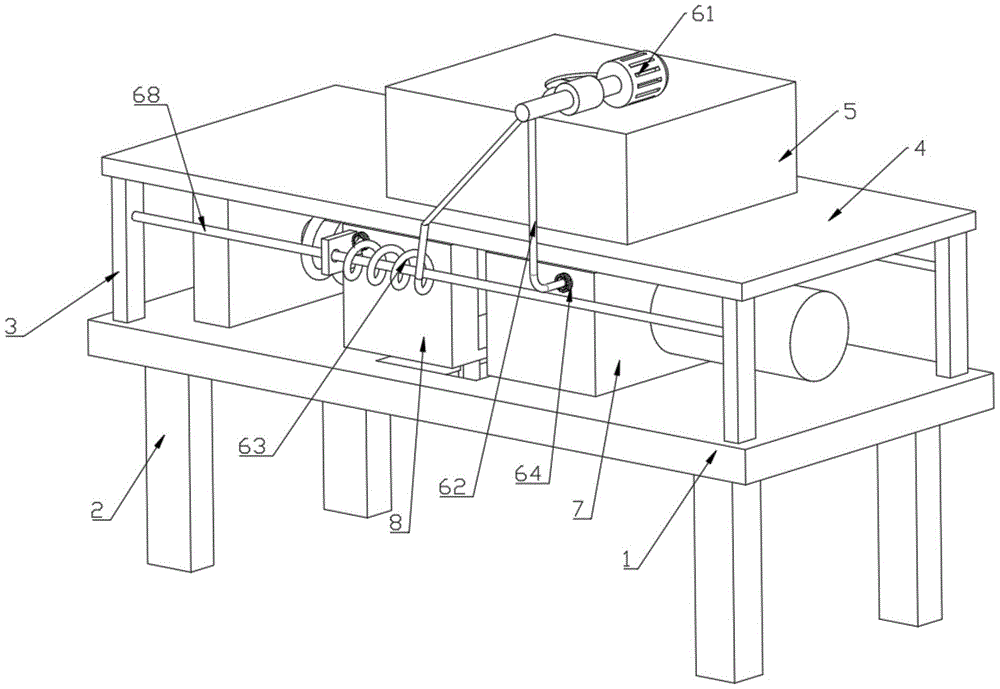
FIG. 1 is a schematic view of the overall structure of the present invention;
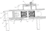
FIG. 2 is a schematic view of a half-section structure of the present invention;
FIG. 3 is a right side view of the structure of the present invention;
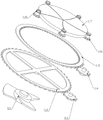
fig. 4 is the schematic view of the split structure of the heat dissipation mechanism of the present invention.
In the figure: 1. a base plate; 2. a support pillar; 3. a support bar; 4. a support plate; 5. a water tank; 6. a cooling mechanism; 61. a water circulating pump; 62. a first water outlet pipe; 63. a second water outlet pipe; 64. fixing a nut; 65. a cooling tube; 66. a first water inlet pipe; 67. a second water inlet pipe; 68. a slide bar; 69. a connecting pipe; 7. determining a module; 8. a movable module; 9. a telescopic cylinder; 10. a water injection pipe; 11. a heat dissipation mechanism; 111. a heat radiation fan; 112. a first transmission fluted disc; 113. a first gear; 114. a second gear; 115. a second transmission fluted disc; 116. a transmission gear; 117. a baffle plate; 118. a torsion spring.
Detailed Description
The technical solution in the embodiments of the present invention will be clearly and completely described below with reference to the accompanying drawings in the embodiments of the present invention.
Referring to fig. 1-4, the present invention provides a technical solution:
the first embodiment is as follows: a circulating cooling device of a precise injection mold comprises a bottom plate 1, wherein a support column 2 is fixedly connected to the lower end face of the bottom plate 1, a support plate 4 is fixedly connected to the upper end face of the bottom plate 1 through a support rod 3, a water tank 5 is fixedly connected to the middle of the upper end face of the support plate 4, a heat dissipation mechanism 11 is arranged on the upper end face of the water tank 5, a fixed module 7 is fixedly connected to the right of the upper end face of the bottom plate 1, a cooling mechanism 6 is arranged on one side of the fixed module 7, a telescopic cylinder 9 is fixedly connected to the left of the lower end face of the bottom plate 1, a movable module 8 is fixedly connected to the output end of the telescopic cylinder 9, the lower end face of the movable module 8 is slidably connected with the bottom plate 1, a water injection pipe 10 is arranged on one side of the water tank 5, the cooling mechanism 6 comprises a circulating water pump 61, a first water outlet pipe 62, a second water outlet pipe 63, a fixing nut 64, a cooling pipe 65, a first water inlet pipe 66, a second water inlet pipe 67, a slide rod 68 and a connecting pipe 69, the water outlet end of the circulating water pump 61 is respectively communicated with the first water outlet pipe 62 and the second water outlet pipe 63, first outlet pipe 62 one end has cooling tube 65 through fixing nut 64 threaded connection, cooling tube 65 one end has first inlet tube 66 and second inlet tube 67 through fixing nut 64 threaded connection respectively, second inlet tube 67 surface sliding connection has slide bar 68, circulating water pump 61 is intake and is held 5 inner chambers of intercommunication water tank through connecting pipe 69, 5 up end and circulating water pump 61 fixed connection of water tank, second outlet pipe 63 one end is passed through fixing nut 64 and cooling tube 65 threaded connection, cover half module 7 and the 8 inner chambers of movable module are provided with cooling tube 65 respectively, second outlet pipe 63 surface and slide bar 68 sliding connection, 3 fixed connection are propped up respectively at slide bar 68 both ends. Because the upper end surface of the water tank 5 is fixedly connected with the circulating water pump 61, during production, materials are injected into the inner cavity of the movable module 8 through the injection molding machine, the circulating water pump 61 is started after injection molding is finished to be matched with the connecting pipe 69, the first water outlet pipe 62 and the second water outlet pipe 63 to guide cooling water in the water tank 5 into the cooling pipe 65, heat of a product is taken away through flowing of the cooling water in the cooling pipe 65, finally the cooling water is poured back into the water tank 5 through the first water inlet pipe 66 and the second water inlet pipe 67, cooling molding of the product is finished, the telescopic cylinder 9 is started after molding is finished to pull the movable module 8 to be separated from the fixed module 7, the product is enabled to fall off freely, the movable module 8 can drive the second water outlet pipe 63 and the second water inlet pipe 67 to slide on the sliding rod 68, and when the mold needs to be replaced, the cooling pipe 65 and the first water outlet pipe 62 can be detached by unscrewing the fixing screw cap 64, A second outlet pipe 63, a first inlet pipe 66 and a second inlet pipe 67.
The second embodiment is different from the first embodiment in that the heat dissipation mechanism 11 includes a heat dissipation fan 111, a first transmission gear disk 112, a first gear 113, a second gear 114, a second transmission gear disk 115, a transmission gear 116, a baffle 117, and a torsion spring 118, one end of the heat dissipation fan 111 is fixedly connected with the first transmission gear disk 112, the outer surface of the first transmission gear disk 112 is engaged with the first gear 113, the upper end surface of the first gear 113 is fixedly connected with the second gear 114 through a rotating shaft, the outer surface of the second gear 114 is engaged with the second transmission gear disk 115, the inner side of the second transmission gear disk 115 is engaged with the transmission gear 116, the upper end surface of the transmission gear 116 is fixedly connected with the baffle 117 through a rotating shaft, the upper end surface of the transmission gear 116 is rotatably connected with the water tank 5 through the torsion spring 118 matching with the rotating shaft, one end of the heat dissipation fan 111 is fixedly connected with the water tank 5 through a connecting frame, a driving motor is disposed inside the heat dissipation fan 111, one sides of the first gear 113 and the second gear 114 are rotatably connected with the water tank 5 through a rotating shaft, and an inner cavity of the water tank 5 is slidably connected with the baffle 117 and the second transmission fluted disc 115. Because one end of the cooling fan 111 is fixedly connected with the water tank 5 through the connecting frame, when cooling starts, the cooling fan 111 can be started to drive the first transmission fluted disc 112 to rotate, the first transmission fluted disc 112 drives the second gear 114 to rotate by being meshed with the first gear 113, the second gear 114 drives the transmission gear 116 to rotate by being meshed with the second transmission fluted disc 115, the transmission gear 116 drives the baffle plate 117 to rotate and open through the rotating shaft, and then heat in the water tank 5 is discharged through the operation of the cooling fan 111, when the cooling fan is not used, the cooling fan 111 is closed, at the moment, the transmission gear 116 automatically resets under the action of the torsion spring 118, and then the baffle plate 117 is driven to reset and close, so that dust is effectively prevented from falling into the water tank 5.
During production, materials are injected into the inner cavity of the movable module 8 through an injection molding machine, after injection molding is finished, the circulating water pump 61 is started to be matched with the connecting pipe 69, the first water outlet pipe 62 and the second water outlet pipe 63 to guide cooling water in the water tank 5 into the cooling pipe 65, heat of a product is taken away through flowing of the cooling water in the cooling pipe 65, finally the cooling water is poured into the water tank 5 through the first water inlet pipe 66 and the second water inlet pipe 67, cooling molding of the product is finished, after molding is finished, the telescopic cylinder 9 is started to pull the movable module 8 to be separated from the fixed module 7, the product is enabled to fall off freely, the movable module 8 can drive the second water outlet pipe 63 and the second water inlet pipe 67 to slide on the sliding rod 68 during movement, when the mold needs to be replaced, the connection between the cooling pipe 65 and the first water outlet pipe 62, the second water outlet pipe 63, the first water inlet pipe 66 and the second water inlet pipe 67 can be detached by unscrewing the fixing screw cap 64, because one end of the cooling fan 111 is fixedly connected with the water tank 5 through the connecting frame, when cooling starts, the cooling fan 111 can be started to drive the first transmission fluted disc 112 to rotate, the first transmission fluted disc 112 drives the second gear 114 to rotate by being meshed with the first gear 113, the second gear 114 drives the transmission gear 116 to rotate by being meshed with the second transmission fluted disc 115, the transmission gear 116 drives the baffle plate 117 to rotate and open through the rotating shaft, and then heat in the water tank 5 is discharged through the operation of the cooling fan 111, when the cooling fan is not used, the cooling fan 111 is closed, at the moment, the transmission gear 116 automatically resets under the action of the torsion spring 118, and then the baffle plate 117 is driven to reset and close, so that dust is effectively prevented from falling into the water tank 5.
It is noted that, herein, relational terms such as first and second, and the like may be used solely to distinguish one entity or action from another entity or action without necessarily requiring or implying any actual such relationship or order between such entities or actions.