CN217343013U - Z-shaped elastic sheet one-time forming mechanism - Google Patents
Z-shaped elastic sheet one-time forming mechanism Download PDFInfo
- Publication number
- CN217343013U CN217343013U CN202123274931.5U CN202123274931U CN217343013U CN 217343013 U CN217343013 U CN 217343013U CN 202123274931 U CN202123274931 U CN 202123274931U CN 217343013 U CN217343013 U CN 217343013U
- Authority
- CN
- China
- Prior art keywords
- bending
- block
- forming
- groove
- positioning
- Prior art date
- Legal status (The legal status is an assumption and is not a legal conclusion. Google has not performed a legal analysis and makes no representation as to the accuracy of the status listed.)
- Expired - Fee Related
Links
- 238000005452 bending Methods 0.000 claims abstract description 66
- 238000003825 pressing Methods 0.000 claims abstract description 19
- 230000001154 acute effect Effects 0.000 abstract description 8
- 238000001179 sorption measurement Methods 0.000 abstract description 3
- 238000010586 diagram Methods 0.000 description 2
- 238000004519 manufacturing process Methods 0.000 description 2
- 238000000465 moulding Methods 0.000 description 2
- 230000009286 beneficial effect Effects 0.000 description 1
- 238000009434 installation Methods 0.000 description 1
- 238000000034 method Methods 0.000 description 1
- 238000012986 modification Methods 0.000 description 1
- 230000004048 modification Effects 0.000 description 1
Images



Classifications
-
- Y—GENERAL TAGGING OF NEW TECHNOLOGICAL DEVELOPMENTS; GENERAL TAGGING OF CROSS-SECTIONAL TECHNOLOGIES SPANNING OVER SEVERAL SECTIONS OF THE IPC; TECHNICAL SUBJECTS COVERED BY FORMER USPC CROSS-REFERENCE ART COLLECTIONS [XRACs] AND DIGESTS
- Y02—TECHNOLOGIES OR APPLICATIONS FOR MITIGATION OR ADAPTATION AGAINST CLIMATE CHANGE
- Y02E—REDUCTION OF GREENHOUSE GAS [GHG] EMISSIONS, RELATED TO ENERGY GENERATION, TRANSMISSION OR DISTRIBUTION
- Y02E60/00—Enabling technologies; Technologies with a potential or indirect contribution to GHG emissions mitigation
- Y02E60/10—Energy storage using batteries
Landscapes
- Bending Of Plates, Rods, And Pipes (AREA)
Abstract
本实用新型公开了一种Z型弹片一次成型机构,包括定位块、成型块和折弯块,定位块的定位表面设置有若干与内部气道连通的气孔,设置于定位块侧面的接头与负压气源连接;成型块设置于定位块的上方,成型块的底部设置有折弯凸块一,以及位于折弯凸台上方的折弯凹槽一;折弯块位于定位块的下方,且倾斜设置,折弯块的顶部设置于折弯凸块一适配的折弯凹槽二,以及与折弯凹槽一适配的折弯凸块二;折弯凸块二的折弯成型面与外侧面的夹角为25°。成型块与倾斜的折弯块配合使用,同步成型Z型弹片的两个45°的锐角,采用负压吸附和压料机构下压组合方式固定产品,保证了产品的定位稳定和定位精度,还保证了产品在折弯时不移位。
The utility model discloses a one-time forming mechanism of a Z-shaped elastic piece, which comprises a positioning block, a forming block and a bending block. The compressed air source is connected; the forming block is arranged above the positioning block, and the bottom of the forming block is provided with a bending protrusion 1 and a bending groove 1 located above the bending protrusion; the bending block is located below the positioning block, and Inclined arrangement, the top of the bending block is arranged on the bending groove 2 adapted to the first bending protrusion, and the second bending protrusion matched with the first bending groove; the bending forming surface of the bending protrusion 2 The angle with the outer side is 25°. The forming block is used in conjunction with the inclined bending block to simultaneously form the two acute angles of 45° of the Z-shaped shrapnel, and the product is fixed by the combination of negative pressure adsorption and pressing mechanism, which ensures the positioning stability and positioning accuracy of the product. It is guaranteed that the product does not shift during bending.
Description
技术领域technical field
本实用新型属于3C产品生产设备技术领域,涉及到一种Z型弹片一次成型机构。The utility model belongs to the technical field of 3C product production equipment, and relates to a Z-shaped elastic piece one-time forming mechanism.
背景技术Background technique
Z型弹片有两个45°的锐角,目前这两个锐角分步骤折弯成型,Z型弹片的折弯成型效率较低,不能满足产能要求。The Z-shaped shrapnel has two acute angles of 45°. At present, these two acute angles are bent in steps. The bending and forming efficiency of the Z-shaped shrapnel is low and cannot meet the production capacity requirements.
实用新型内容Utility model content
本实用新型要解决的技术问题是:提供一种能一步成型Z型弹片两个锐角的成型机构。The technical problem to be solved by the utility model is to provide a forming mechanism capable of forming two acute angles of the Z-shaped elastic piece in one step.
为解决上述技术问题,本实用新型采用的技术方案如下:In order to solve the above-mentioned technical problems, the technical scheme adopted by the utility model is as follows:
一种Z型弹片一次成型机构,包括定位块、成型块和折弯块,所述定位块的定位表面设置有若干与内部气道连通的气孔,设置于定位块侧面的接头与负压气源连接;所述成型块设置于所述定位块的上方,所述成型块的底部设置有折弯凸块一,以及位于所述折弯凸台上方的折弯凹槽一;所述折弯块位于所述定位块的下方,且倾斜设置,所述折弯块的顶部设置于所述折弯凸块一适配的折弯凹槽二,以及与所述折弯凹槽一适配的折弯凸块二;所述折弯凸块二的折弯成型面与外侧面的夹角为25°;所述折弯块由气缸驱动向靠近或者远离定位块的方向移动。A Z-shaped shrapnel one-time forming mechanism includes a positioning block, a forming block and a bending block, the positioning surface of the positioning block is provided with a number of air holes communicating with the internal air passage, the joints arranged on the side of the positioning block and the negative pressure air source connection; the forming block is arranged above the positioning block, and the bottom of the forming block is provided with a bending bump 1 and a bending groove 1 located above the bending boss; the bending block It is located below the positioning block and is inclined, and the top of the bending block is set in the second bending groove, which is adapted to the first bending protrusion, and the second bending groove that is adapted to the first bending groove. Bending convex block 2; the included angle between the bending forming surface of the bending convex block 2 and the outer side surface is 25°; the bending block is driven by the cylinder to move toward or away from the positioning block.
与现有技术相比,本实用新型的有益效果是:Compared with the prior art, the beneficial effects of the present utility model are:
1.采用负压吸附和压料机构下压组合方式固定产品,保证了产品的定位稳定和定位精度,还保证了产品在折弯时不移位;1. The product is fixed by the combination of negative pressure adsorption and pressing mechanism, which ensures the positioning stability and positioning accuracy of the product, and also ensures that the product does not shift during bending;
2.成型块与倾斜的折弯块配合使用,同步成型Z型弹片的两个45°的锐角,且成型上锐角的折弯凸块二预留了20°的折弯回弹,保证了Z型弹片的成型质量。2. The forming block is used in conjunction with the inclined bending block to simultaneously form the two acute angles of 45° of the Z-shaped shrapnel, and the second acute angle of the forming block has a 20° bending rebound, which ensures the Z-shaped spring. The forming quality of the shrapnel.
附图说明Description of drawings
为了更清楚地说明本实用新型实施例中的技术方案,下面将对实施例描述中所需要使用的附图作简单地介绍。In order to illustrate the technical solutions in the embodiments of the present utility model more clearly, the accompanying drawings required to be used in the description of the embodiments will be briefly introduced below.
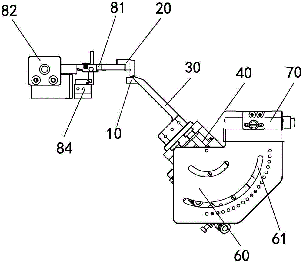
图1为Z型弹片一次成型机构的结构示意图;Fig. 1 is a structural schematic diagram of a Z-shaped shrapnel one-time forming mechanism;
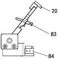
图2为压料机构的侧视图;Figure 2 is a side view of the pressing mechanism;
图3为压料机构的侧视图(打开状态);Figure 3 is a side view of the pressing mechanism (open state);
图4为成型块与折弯块的成型状态示意图。FIG. 4 is a schematic diagram of the forming state of the forming block and the bending block.
具体实施方式Detailed ways
下面将结合附图对本实用新型实施例中的技术方案进行清楚、完整地描述。The technical solutions in the embodiments of the present invention will be clearly and completely described below with reference to the accompanying drawings.
实施例Example
如图1中所示的Z型弹片一次成型机构,包括定位块10、成型块20和折弯块30,定位块10的定位表面设置有若干与内部气道连通的气孔,设置于定位块10侧面的接头与负压气源连接。参见图2和3,成型块20设置于定位块10的上方,成型块20的底部设置有折弯凸块一21,以及位于折弯凸台上方的折弯凹槽一22;折弯块30位于定位块10的下方,且倾斜设置,折弯块30的顶部设置于折弯凸块一21适配的折弯凹槽二31,以及与折弯凹槽一22适配的折弯凸块二32;折弯凸块二32的折弯成型面与外侧面的夹角为25°;折弯块30由气缸40驱动向靠近或者远离定位块10的方向移动。As shown in FIG. 1, the Z-shaped elastic piece one-time forming mechanism includes a
将产品放在定位块10上定位吸附固定,成型块20向下压住产品,气缸驱动折弯块30向产品移动,折弯凸块一21与折弯凹槽二31配合成型下锐角,折弯凸块二32与折弯凹槽一22配合成型上锐角(参见图4)。折弯凸块二32预留了20°的折弯回弹,保证了Z型弹片的成型质量。Place the product on the
作为本实施例的改进,气缸40的缸体安装于支架60上,支架中设置有弧形调节槽61,于弧形调节槽内安装有一基板,气缸的缸体固定于基板中,折弯块30的角度可以通过缸体在支架上的安装角度进行调节。As an improvement of this embodiment, the cylinder body of the
优选地,支架的底部滑接于平移气缸70的水平滑台上,共同通过设计两个气缸的运动行程和启动时间,可以对应成型多种变形设计的Z型特征。Preferably, the bottom of the bracket is slidably connected to the horizontal sliding table of the
作为本实施例的改进,本成型机构还包括压料机构,压料机构驱动成型块20下压产品。优选地,压料机构包括压板81、旋转座82、勾杆83和固定座84,压板的一端通过转轴安装于旋转座中,成型块20固定于压板的另一端。将产品放置于定位块10之后,向下旋转压板,使压板压住产品。在压板中设置有通槽,勾杆安装于通槽内,勾杆侧面的凸块与通槽中的转轴连接,凸块与压板之间通过弹簧85连接,在弹簧不受外力情况下,勾杆始终处于竖直状态。勾杆的底部设置有勾部831,固定座的侧面设置有勾槽841,勾部进入勾槽内,压板在水平状态被固定,成型块压住产品。As an improvement of this embodiment, the molding mechanism further includes a pressing mechanism, and the pressing mechanism drives the forming
对这些实施例的多种修改对本领域的专业技术人员来说将是显而易见的,本文中所定义的一般原理可以在不脱离本实用新型的精神或范围的情况下,在其它实施例中实现。因此,本实用新型将不会被限制于本文所示的这些实施例,而是要符合与本文所公开的原理和新颖特点相一致的最宽的范围。Various modifications to these embodiments will be readily apparent to those skilled in the art, and the generic principles defined herein may be implemented in other embodiments without departing from the spirit or scope of the present invention. Thus, the present invention is not intended to be limited to the embodiments shown herein, but is to be accorded the widest scope consistent with the principles and novel features disclosed herein.
Claims (5)
Priority Applications (1)
| Application Number | Priority Date | Filing Date | Title |
|---|---|---|---|
| CN202123274931.5U CN217343013U (en) | 2021-12-23 | 2021-12-23 | Z-shaped elastic sheet one-time forming mechanism |
Applications Claiming Priority (1)
| Application Number | Priority Date | Filing Date | Title |
|---|---|---|---|
| CN202123274931.5U CN217343013U (en) | 2021-12-23 | 2021-12-23 | Z-shaped elastic sheet one-time forming mechanism |
Publications (1)
| Publication Number | Publication Date |
|---|---|
| CN217343013U true CN217343013U (en) | 2022-09-02 |
Family
ID=83039751
Family Applications (1)
| Application Number | Title | Priority Date | Filing Date |
|---|---|---|---|
| CN202123274931.5U Expired - Fee Related CN217343013U (en) | 2021-12-23 | 2021-12-23 | Z-shaped elastic sheet one-time forming mechanism |
Country Status (1)
| Country | Link |
|---|---|
| CN (1) | CN217343013U (en) |
Cited By (1)
| Publication number | Priority date | Publication date | Assignee | Title |
|---|---|---|---|---|
| CN116851522A (en) * | 2023-07-05 | 2023-10-10 | 福立旺精密机电(中国)股份有限公司 | An auxiliary positioning device and positioning method for a shrapnel curling forming machine |
-
2021
- 2021-12-23 CN CN202123274931.5U patent/CN217343013U/en not_active Expired - Fee Related
Cited By (1)
| Publication number | Priority date | Publication date | Assignee | Title |
|---|---|---|---|---|
| CN116851522A (en) * | 2023-07-05 | 2023-10-10 | 福立旺精密机电(中国)股份有限公司 | An auxiliary positioning device and positioning method for a shrapnel curling forming machine |
Similar Documents
| Publication | Publication Date | Title |
|---|---|---|
| CN117532212B (en) | A hardware welding anti-deviation auxiliary device | |
| CN217343012U (en) | Elastic piece multi-angle bending forming equipment | |
| CN110695207A (en) | Punching and bending integrated jig and processing equipment | |
| CN206065398U (en) | A kind of New slide water gap device | |
| CN110465588A (en) | A kind of more tongue piece fixture for forming of flip-over type Rouno Cormer Pregrinding Wheel and its application method | |
| CN210816966U (en) | Punching position adjustable punching jig and punching device | |
| CN217831454U (en) | Drawing die with double blank pressing forces | |
| CN216226463U (en) | A new type of integrated plastic forming structure | |
| CN207577802U (en) | The automatic assembling device of gauge table diaphragm unit | |
| CN215207109U (en) | A screening device for earphone plugs | |
| CN213671430U (en) | Novel stamping die positioning structure | |
| CN222987552U (en) | Plastic bottom shell deformation correction tool | |
| CN210023493U (en) | A bending and embossing die | |
| CN223719309U (en) | A clamping mechanism and device thereof | |
| CN216442658U (en) | A punching device for financial accounting vouchers | |
| CN218315495U (en) | Mould for manufacturing paper cup with inclined edge sealing | |
| CN205887738U (en) | Inside swan neck system of refrigerator compressor exhaust pipe | |
| CN209061947U (en) | A connecting rod in a punch | |
| CN223999064U (en) | Semi-automatic drawer box bubble pressing machine | |
| CN221698363U (en) | Sucking disc device for engraver | |
| CN219381792U (en) | An automatic tablet pressing mechanism for carton production | |
| CN220146498U (en) | A laminating machine for silicone sheets | |
| CN223902714U (en) | A high-efficiency stamping and forming device for copper sheets | |
| CN217941640U (en) | Bending device is used in steel processing | |
| CN222875078U (en) | Steam generator mould for steam box |
Legal Events
| Date | Code | Title | Description |
|---|---|---|---|
| GR01 | Patent grant | ||
| GR01 | Patent grant | ||
| CF01 | Termination of patent right due to non-payment of annual fee | ||
| CF01 | Termination of patent right due to non-payment of annual fee |
Granted publication date: 20220902 |