Drawer unit of low-voltage switch cabinet
Technical Field
The utility model belongs to the technical field of the low-voltage switchgear, specifically say so and relate to a low-voltage switchgear drawer unit.
Background
The low-voltage switch cabinet is widely applied to power plants, substations, industrial and mining enterprises and high-rise buildings. In the field of low-voltage distribution equipment of an electric power system, a drawer type switch cabinet belongs to relatively high-grade distribution equipment and consists of a plurality of drawer functional units. The drawer functional unit is characterized in that a main functional electric device is arranged in a shell formed by a drawer mechanical structure, and the drawer mechanical structure comprises mechanisms of pushing, withdrawing, interlocking and the like, and has the characteristics of convenience in maintenance, convenience in interchange, safety, reliability and the like. The drawer of the low-voltage switch cabinet on the market at present generally adopts two propulsion modes of hand cranking and hand pulling, is used for controlling safe operation of drawer functional units in the switch cabinet from entering to the process of connecting all levels of a main circuit, and has three position states of connection, test and isolation.
In the switching process of connecting, testing and isolating positions of a drawer unit of a low-voltage switch cabinet at present, the traditional switching means is generally realized by pushing and pulling the whole drawer into and out of the switch cabinet body to change the position of a drawer body, when the drawer is pulled out from the switching position, the original protection grade of the drawer can be changed, and when the use environment needs a high protection grade, the use requirement cannot be met; meanwhile, when the position of the drawer unit is changed in the existing high-protection state, the drawer unit depends on the independent movement of a primary plug-in, other electrical components are fixedly installed as a common drawer, relative displacement during the switching of the connection, test and isolation states of the three positions occurs in the plug-in body or on a connecting conductor near the plug-in, and the uncertainty generated by sliding friction generated by the relative displacement can reduce the stability of electric connection;
SUMMERY OF THE UTILITY MODEL
The utility model discloses an aim at be exactly to the defect that above-mentioned current low-voltage switchgear drawer unit exists, provide a low-voltage switchgear drawer unit, through built-in device mounting panel in the drawer unit, utilize the relative motion of device mounting panel and drawer unit shell to realize drawer unit connection, experimental, keep apart three position state and switch, improve protection level, further improved low-voltage switchgear's safety performance.
Technical scheme
In order to realize the technical purpose, the utility model provides a low-voltage switchgear drawer unit, its characterized in that: the device comprises a drawer outer shell, a device mounting plate is arranged in an inner frame of the drawer outer shell and can slide back and forth, an internal electric device, a primary plug-in and a secondary plug-in are arranged on the device mounting plate and can be arranged together with the device mounting plate in the inner frame of the drawer outer shell to slide back and forth to realize the switching of the states of three positions of drawer unit connection, test and isolation.
Further, the device mounting panel is connected with actuating mechanism, actuating mechanism can drive the device mounting panel is in make a round trip to slide in the drawer shell inside casing, the dress of circuit breaker operating handle subassembly is in on the drawer shell with circuit breaker on the device mounting panel is connected and can be controlled the combined floodgate and the separating brake of circuit breaker.
Furthermore, the drawer outer shell comprises a drawer bottom plate and a drawer front door, the drawer bottom plate and the drawer front door are combined into a frame-shaped structure, and the device mounting plate is mounted on a sliding rail in the inner frame of the drawer outer shell and can slide back and forth.
Further, the driving mechanism comprises a pushing screw rod, the pushing screw rod is fixedly arranged on the device mounting plate, and one end of the folding crank is connected with the pushing screw rod.
Further, circuit breaker operating handle subassembly includes the circuit breaker handle, and circuit breaker handle transmission shaft sleeve one end dress is in on the circuit breaker handle, the other end is connected with the circuit breaker action bars, thereby circuit breaker handle rotates the in-process and can drive through circuit breaker handle transmission shaft sleeve the circuit breaker action bars rotates and realizes the switching-on and switching-off operation of circuit breaker.
Furthermore, the breaker operating rod is embedded in a square hole in the breaker handle transmission shaft sleeve and can axially slide.
Further, the breaker handle is mounted on the drawer front door.
Advantageous effects
The utility model provides a pair of low-voltage switchgear drawer unit has the advantage of following several aspects:
(1) the device mounting plate can carry internal electric devices, the primary plug-in unit and the secondary plug-in unit together and moves back and forth along the motion direction of the sliding rail, so that when three positions are switched, the drawer shell body does not need to move, the relative position of the drawer shell body and the cabinet body is not changed, and the protection grade is improved
(2) A front door structure of the drawer in the drawer shell can be coated with a sealing rubber strip, so that the dustproof and waterproof effects are improved;
(3) the components and the copper bars such as the primary plug-in components and the circuit breakers can be fixedly connected on the component mounting plate stably and reliably, and the uncertainty of electric connection is reduced.
(4) The electric device moves along with the device mounting plate, so that the stroke change of the breaker operating rod can be caused, and the telescopic breaker operating rod can simultaneously meet the requirements of stroke change and torque transmission.
Drawings
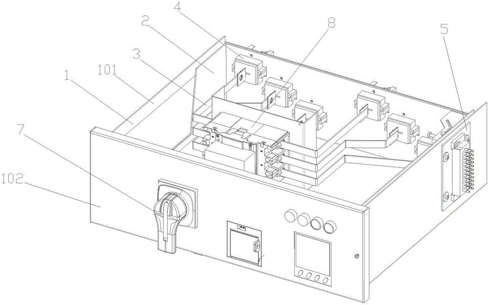
Fig. 1 is a first product diagram of a drawer unit according to an embodiment of the present invention.
Fig. 2 is a second product diagram of the drawer unit according to the embodiment of the present invention.
Detailed Description
The technical solution of the present invention will be described clearly and completely with reference to the accompanying drawings, and obviously, the described embodiments are some, but not all embodiments of the present invention. Based on the embodiments in the present invention, all other embodiments obtained by a person skilled in the art without creative efforts belong to the protection scope of the present invention.
In the description of the present invention, it should be noted that the terms "inner", "outer", "front", "rear", "left", "right", "common side", "standby side", and the like indicate orientations or positional relationships based on the orientations or positional relationships shown in the drawings, and are only for convenience of description and simplification of description, but do not indicate or imply that the device or element referred to must have a specific orientation, be constructed and operated in a specific orientation, and thus, should not be construed as limiting the present invention. Furthermore, the terms "first," "second," and "third" are used for descriptive purposes only and are not to be construed as indicating or implying relative importance.
In the description of the present invention, it is to be noted that, unless otherwise explicitly specified or limited, the terms "mounted" and "connected" are to be interpreted broadly, and may be, for example, fixedly connected, detachably connected, or integrally connected; can be mechanically or electrically connected; they may be connected directly or indirectly through intervening media, or they may be interconnected between two elements. The specific meaning of the above terms in the present invention can be understood in specific cases to those skilled in the art.
The present invention will be described in further detail with reference to specific embodiments and drawings.
Examples
As shown in the attached figure 1, the drawer unit of the low-voltage switch cabinet comprises a drawer outer shell 1, a device mounting plate 2 is arranged in an inner frame of the drawer outer shell 1 and can slide back and forth, and an internal electric device 3, a primary plug-in unit 4 and a secondary plug-in unit 5 are arranged on the device mounting plate 2 and can slide back and forth together with the device mounting plate 2 in the inner frame of the drawer outer shell 1 to realize the switching of the states of the connection, the test and the isolation of the drawer unit. As shown in the attached drawing 2, the device mounting plate 2 is connected with a driving mechanism 6, the driving mechanism 6 can drive the device mounting plate 2 to slide back and forth in the inner frame of the drawer shell 1, and a breaker operating handle assembly 7 is arranged on the drawer shell 1 and connected with a breaker 8 on the device mounting plate 2 to control the closing and opening of the breaker 8. In this embodiment, the drawer outer casing 1 includes a drawer bottom plate 101 and a drawer front door 102, the drawer bottom plate 101 and the drawer front door 102 are combined into a frame structure, and the device mounting plate 2 is mounted on a slide rail 103 in an inner frame of the drawer outer casing 1 and can slide back and forth. The driving mechanism 6 comprises a pushing screw 601, the pushing screw 601 is fixedly arranged on the device mounting plate 2, and one end of a folding crank 602 is connected with the pushing screw 601. The circuit breaker operating handle assembly 7 includes a circuit breaker handle 701, and the circuit breaker handle 701 is mounted on the drawer front door 102.
Breaker handle driving shaft sleeve 702 one end dress is in on the breaker handle 701, the other end is connected with circuit breaker action bars 703, thereby circuit breaker handle 701 rotates the in-process and can drive through breaker handle driving shaft sleeve 702 circuit breaker action bars 703 rotates and realizes the switching-on and switching-off operation of circuit breaker 8. Specifically, the breaker operating rod 703 is fitted in a square hole of the breaker handle driving bushing 702 so as to be axially slidable.
According to the drawer unit of the low-voltage switch cabinet, the device mounting plate can carry internal electric devices, primary plug-in components and secondary plug-in components together and move back and forth along the motion direction of the slide rail, so that when three positions are switched, the drawer shell body does not need to move, the relative position of the drawer shell body and the cabinet body is not changed, and the protection level is improved; a front door structure of the drawer in the drawer shell can be coated with a sealing rubber strip, so that the dustproof and waterproof effects are improved; the components and the copper bars such as the primary plug-in components and the circuit breakers can be fixedly connected on the component mounting plate stably and reliably, and the uncertainty of electric connection is reduced. The electrical device can lead to circuit breaker action bars stroke change along with the motion of device mounting panel, and the circuit breaker action bars inlays and is adorned can axial slip satisfy stroke change and moment transmission simultaneously in the square hole on the circuit breaker handle driving shaft sleeve 702.
Finally, it should be noted that: the above embodiments are only used to illustrate the technical solution of the present invention, and not to limit the same; while the present invention has been described in detail with reference to the foregoing embodiments, it will be understood by those skilled in the art that; the technical solutions described in the foregoing embodiments may still be modified, or some or all of the technical features may be equivalently replaced; such modifications and substitutions do not depart from the spirit and scope of the present invention.