CN217318137U - Efficient hot-melt pressure-sensitive adhesive slitting device - Google Patents
Efficient hot-melt pressure-sensitive adhesive slitting device Download PDFInfo
- Publication number
- CN217318137U CN217318137U CN202220638013.1U CN202220638013U CN217318137U CN 217318137 U CN217318137 U CN 217318137U CN 202220638013 U CN202220638013 U CN 202220638013U CN 217318137 U CN217318137 U CN 217318137U
- Authority
- CN
- China
- Prior art keywords
- sensitive adhesive
- melt pressure
- pressure sensitive
- hot melt
- processing groove
- Prior art date
- Legal status (The legal status is an assumption and is not a legal conclusion. Google has not performed a legal analysis and makes no representation as to the accuracy of the status listed.)
- Active
Links
- 239000004820 Pressure-sensitive adhesive Substances 0.000 title claims abstract description 59
- 239000012943 hotmelt Substances 0.000 title claims abstract description 55
- 238000009434 installation Methods 0.000 claims description 11
- 238000000926 separation method Methods 0.000 claims description 7
- 230000000149 penetrating effect Effects 0.000 claims description 4
- 239000000463 material Substances 0.000 abstract description 4
- 238000007599 discharging Methods 0.000 abstract 1
- 238000000034 method Methods 0.000 abstract 1
- 238000005192 partition Methods 0.000 description 6
- 230000000694 effects Effects 0.000 description 3
- 239000000155 melt Substances 0.000 description 2
- 238000002844 melting Methods 0.000 description 2
- 230000008018 melting Effects 0.000 description 2
- 239000002390 adhesive tape Substances 0.000 description 1
- 230000009286 beneficial effect Effects 0.000 description 1
- 230000006835 compression Effects 0.000 description 1
- 238000007906 compression Methods 0.000 description 1
- 230000007547 defect Effects 0.000 description 1
- 239000004744 fabric Substances 0.000 description 1
- 239000003292 glue Substances 0.000 description 1
- 238000010438 heat treatment Methods 0.000 description 1
- 239000011347 resin Substances 0.000 description 1
- 229920005989 resin Polymers 0.000 description 1
Images



Classifications
-
- Y—GENERAL TAGGING OF NEW TECHNOLOGICAL DEVELOPMENTS; GENERAL TAGGING OF CROSS-SECTIONAL TECHNOLOGIES SPANNING OVER SEVERAL SECTIONS OF THE IPC; TECHNICAL SUBJECTS COVERED BY FORMER USPC CROSS-REFERENCE ART COLLECTIONS [XRACs] AND DIGESTS
- Y02—TECHNOLOGIES OR APPLICATIONS FOR MITIGATION OR ADAPTATION AGAINST CLIMATE CHANGE
- Y02E—REDUCTION OF GREENHOUSE GAS [GHG] EMISSIONS, RELATED TO ENERGY GENERATION, TRANSMISSION OR DISTRIBUTION
- Y02E60/00—Enabling technologies; Technologies with a potential or indirect contribution to GHG emissions mitigation
- Y02E60/10—Energy storage using batteries
Landscapes
- Coating Apparatus (AREA)
Abstract
The utility model discloses an efficient hot melt pressure sensitive adhesive cuts device, including workstation, processing groove and mounting bracket, the front of workstation is run through and is installed electric telescopic handle, the processing groove has been seted up at the top of workstation, the mounting bracket is installed at the top of workstation, and the mounting bracket is located the outside of processing groove, the fixed plate is installed to the inboard symmetry of mounting bracket, the separating tank has been seted up at the top of fixed plate, the pneumatic cylinder has been run through and has been installed at the top of mounting bracket. The utility model discloses in when the cutting knife cutting was accomplished, in order to prevent that hot melt pressure sensitive adhesive from linking on the cutting knife, can upwards rise after the cutting knife cutting was accomplished, thereby hot melt pressure sensitive adhesive can receive blockking of separator and drop, make the cutting knife can cut hot melt pressure sensitive adhesive better, can not influence processing because of the hot melt pressure sensitive adhesive of adhesion, promote the polylith material through electric telescopic handle among the device simultaneously and process, automatic discharging moreover, convenience very is high-efficient.
Description
Technical Field
The utility model relates to a hot melt pressure sensitive adhesive technical field specifically is an efficient hot melt pressure sensitive adhesive divides cuts device.
Background
The hot-melt pressure-sensitive adhesive is mainly prepared by mixing and heating rubber, resin and other materials, is mainly used by being coated on articles needing to be used and is coated on base materials such as tissue paper, cloth and the like to form an adhesive tape.
The existing hot-melt pressure-sensitive adhesive slitting device has the defects that:
1. patent document CN211415400U discloses a hot melt pressure sensitive adhesive slitting device convenient to change cutter, "including the cutting machine body, connect base, cutter, locating part and base, the top of cutting machine body is fixed with the pneumatic cylinder, and the bottom of pneumatic cylinder is provided with the hydraulic stem, the left and right sides of hydraulic stem all is provided with the buckle, and the bottom surface of hydraulic stem is provided with first slide rail, the opening has been seted up to the centre at the upper and lower both ends of first slide rail, connect the base and fix the bottom at the hydraulic stem, and the top surface of just connecting the base is provided with first slider. This hot melt pressure sensitive adhesive divides and cuts device convenient to change cutter, be provided with the fixed block, aim at spacing hole with the fixed block of cutter both sides, then insert the cutter and connect the base bottom, compression spring gets into the recess when the fixed block is inside, when the fixed block removes to spacing hole, the spring pops out the fixed block, thereby drive the locating part and pop out, the cutter is fixed in connecting the base bottom, it is more convenient to make the different cutters of change, "but this hot melt pressure sensitive adhesive divides and cuts the device, do not install cutting knife and hot melt pressure sensitive adhesive's separator, thereby can make the cutting knife accomplish the back at the cutting, hot melt pressure sensitive adhesive can glue and even on love the cutting knife.
SUMMERY OF THE UTILITY MODEL
An object of the utility model is to provide a device is cut to efficient hot melt pressure sensitive adhesive to solve the problem that proposes in the above-mentioned background art.
In order to achieve the above object, the utility model provides a following technical scheme: an efficient hot-melt pressure-sensitive adhesive cutting device comprises a workbench, a processing groove and an installation frame, wherein an electric telescopic rod penetrates through the front surface of the workbench, the top of the workbench is provided with the processing groove, the installation frame is installed at the top of the workbench, and the installation frame is positioned on the outer side of the processing groove;
the inner sides of the mounting frames are symmetrically provided with fixed plates, and the tops of the fixed plates are provided with separating grooves;
and a pneumatic cylinder is installed at the top of the mounting frame in a penetrating manner.
Preferably, the bottom of the workbench is symmetrically provided with supporting legs.
Preferably, the push pedal is installed to electric telescopic handle's output, and the push pedal is located the inboard in processing groove.
Preferably, install the division board on the bottom inner wall of processing groove, the division board is located the below of push pedal, has seted up on the bottom inner wall of processing groove and has cut the groove, has seted up the discharge gate on the bottom inner wall of processing groove, and the discharge gate is located the rear of division board, and the flitch is installed to the inboard of discharge gate.
Preferably, a controller is installed on one side of the installation frame, and sliding grooves are symmetrically formed in the inner side of the installation frame.
Preferably, a separation plate is installed at the bottom of the separation tank.
Preferably, the output end of the pneumatic cylinder is provided with a mounting plate, and the bottom of the mounting plate is provided with a cutting knife.
Compared with the prior art, the beneficial effects of the utility model are that:
1. the utility model discloses an install the fixed plate at the inboard symmetry of mounting bracket, the separating tank has been seted up at the top of fixed plate, the separating tank runs through the bottom of fixed plate, and the bottom symmetry in categorised groove installs the separator plate, the cutting knife can be through the separating tank when cutting hot melt pressure sensitive adhesive, when the cutting knife cutting is accomplished, in order to prevent that hot melt pressure sensitive adhesive from linking on the cutting knife, can upwards rise after the cutting knife cutting is accomplished, thereby hot melt pressure sensitive adhesive can receive blockking of separator plate and drop, make the cutting knife can better cut hot melt pressure sensitive adhesive, can not influence processing because of the hot melt pressure sensitive adhesive of adhesion.
2. The utility model discloses a processing groove has been seted up at the top of workstation, the front of workstation is run through simultaneously and is installed electric telescopic handle, when hot melt pressure sensitive adhesive cuts, can put into two simultaneously and cut, separate two hot melt pressure sensitive adhesives through the division board, electric telescopic handle can drive the push pedal and remove, thereby promote the bottom of cutting knife with hot melt pressure sensitive adhesive and cut, can continue to promote hot melt pressure sensitive adhesive after the cutting is accomplished, the hot melt pressure sensitive adhesive that makes the cutting accomplish promotes in the discharge gate, carry out the ejection of compact along ejection of compact board, thereby make hot melt pressure sensitive adhesive's processing high efficiency more.
Drawings
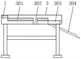
Fig. 1 is a perspective view of the present invention;
FIG. 2 is a schematic view of the structure of the processing tank of the present invention;
fig. 3 is a schematic structural view of a fixing plate of the present invention;
fig. 4 is a schematic view of the pneumatic cylinder of the present invention.
In the figure: 1. a work table; 101. supporting legs; 2. an electric telescopic rod; 201. pushing the plate; 3. processing a tank; 301. a partition plate; 302. cutting the groove; 303. a discharge port; 304. a discharge plate; 4. a mounting frame; 401. a controller; 402. a chute; 5. a fixing plate; 501. a separation tank; 502. a separation plate; 6. a pneumatic cylinder; 601. mounting a plate; 602. a cutting knife.
Detailed Description
The technical solutions in the embodiments of the present invention will be described clearly and completely with reference to the accompanying drawings in the embodiments of the present invention, and it is obvious that the described embodiments are only some embodiments of the present invention, not all embodiments. Based on the embodiments in the present invention, all other embodiments obtained by a person skilled in the art without creative work belong to the protection scope of the present invention.
In the description of the present invention, it should be noted that the terms "upper", "lower", "inner", "outer", "front end", "rear end", "both ends", "one end", "the other end" and the like indicate orientations or positional relationships based on the orientations or positional relationships shown in the drawings, and are only for convenience of description and simplification of description, but do not indicate or imply that the device or element to which the reference is made must have a specific orientation, be constructed in a specific orientation, and be operated, and thus, should not be construed as limiting the present invention. Furthermore, the terms "first" and "second" are used for descriptive purposes only and are not to be construed as indicating or implying relative importance.
In the description of the present invention, it is to be noted that, unless otherwise explicitly specified or limited, the terms "mounted," "disposed," "connected," and the like are to be construed broadly, and for example, "connected" may be either fixedly connected or detachably connected, or integrally connected; can be mechanically or electrically connected; they may be connected directly or indirectly through intervening media, or they may be interconnected between two elements. The specific meaning of the above terms in the present invention can be understood in specific cases to those skilled in the art.
Referring to fig. 1-2, the present invention provides an embodiment: an efficient hot-melt pressure-sensitive adhesive slitting device;
comprises a workbench 1, an electric telescopic rod 2, a processing groove 3 and a mounting rack 4, the front of the workbench 1 is provided with the electric telescopic rod 2 in a penetrating way, the bottom of the workbench 1 is symmetrically provided with supporting legs 101, the output end of the electric telescopic rod 2 is provided with a push plate 201, the push plate 201 is positioned at the inner side of the processing groove 3, the workbench 1 provides a position for the processing groove 3 at the top, and simultaneously provides a position for the mounting of the mounting rack 4, the supporting legs 101 are used for improving the height of the workbench 1, the device is convenient for workers to use, the electric telescopic rod 2 can convert electric energy into kinetic energy after being electrified, thereby driving the push plate 201 at the output end to move, providing power for the movement of the push plate 201, the push plate 201 is positioned inside the processing groove 3, the push plate 201 is used for pushing hot melt pressure sensitive adhesive needing to be processed, thereby enabling the hot melt pressure sensitive adhesive to move to the cutting position, after cutting, the cutting tool can also move to a discharge port 303 to discharge materials, a processing tank 3 is arranged at the top of the workbench 1, a partition plate 301 is arranged on the inner wall of the bottom of the processing tank 3, the partition plate 301 is positioned below the push plate 201, a cutting groove 302 is arranged on the inner wall of the bottom of the processing tank 3, a discharge port 303 is arranged on the inner wall of the bottom of the processing tank 3, the discharge port 303 is positioned behind the partition plate 301, a discharge plate 304 is arranged on the inner side of the discharge port 303, an installation frame 4 is arranged at the top of the workbench 1, the installation frame 4 is positioned on the outer side of the processing tank 3, a controller 401 is arranged on one side of the installation frame 4, sliding grooves 402 are symmetrically arranged on the inner side of the installation frame 4, the processing tank 3 provides space for processing of hot melt pressure sensitive adhesive, the partition plate 301 plays a separating role to separate the processing tank 3, so that two hot melt pressure sensitive adhesives can be processed together, and the partition plate 301 also plays a limiting role, make hot melt pressure sensitive adhesive more stable when removing, cutting groove 302 provides the space for the cutting of cutting knife 602, discharge gate 303 plays the effect of the ejection of compact, accomplish the hot melt pressure sensitive adhesive ejection of compact for the cutting and provide the space, play flitch 304 plays the effect of direction, make hot melt pressure sensitive adhesive can arrive appointed position along going out flitch 304, mounting bracket 4 provides the mounted position for pneumatic cylinder 6, make pneumatic cylinder 6 can install in suitable position, controller 401 is used for controlling the device's operation, spout 402 makes mounting panel 601 more stable when removing.
Referring to fig. 3, the present invention provides an embodiment: an efficient hot-melt pressure-sensitive adhesive slitting device;
including fixed plate 5, fixed plate 5 is installed to the inboard symmetry of mounting bracket 4, separating tank 501 has been seted up at the top of fixed plate 5, separating plate 502 is installed to separating tank 501's bottom, fixed plate 5 provides for the position for seting up of separating tank 501, separating tank 501 provides the space for the removal of cutting knife 602, can not block it, separating plate 502 is used for separating hot melt pressure sensitive adhesive and cutting knife 602, can upwards rise after the cutting knife 602 cutting is accomplished, and hot melt pressure sensitive adhesive can receive blockking of separating plate 502 thereby drops, make cutting knife 602 can better cut hot melt pressure sensitive adhesive, can not influence processing because of the hot melt pressure sensitive adhesive of adhesion.
Referring to fig. 4, the present invention provides an embodiment: an efficient hot-melt pressure-sensitive adhesive slitting device;
including pneumatic cylinder 6, pneumatic cylinder 6 is installed in the top of mounting bracket 4 through, mounting panel 601 is installed to pneumatic cylinder 6's output, cutting knife 602 is installed to mounting panel 601's bottom, pneumatic cylinder 6 can drive the mounting panel 601 of output and remove, connecting piece and spout 402's inboard looks gomphosis is passed through in mounting panel 601's the outside, thereby make mounting panel 601 remove more stable, cutting knife 602 plays the effect of cutting, be used for cutting hot melt pressure sensitive adhesive.
The working principle is as follows: before using hot melt pressure sensitive adhesive to divide and cut the device, should examine earlier whether this hot melt pressure sensitive adhesive divides and cuts the device and whether has the problem that influences the use, at first cut the device with hot melt pressure sensitive adhesive and place the position that needs use, the hot melt pressure sensitive adhesive that will need processing is placed in processing groove 3, promote the below of cutting knife 602 through push pedal 201 with melting pressure sensitive adhesive, utilize pneumatic cylinder 6 to drive cutting knife 602 and remove, thereby to melting pressure sensitive adhesive and cutting, cutting knife 602 can upwards remove, it drops to utilize the melt pressure sensitive adhesive that separator 502 made the adhesion, push pedal 201 can push away the ejection of compact in the discharge gate 303 with the melt pressure sensitive adhesive that the cutting was accomplished.
It is obvious to a person skilled in the art that the invention is not restricted to details of the above-described exemplary embodiments, but that it can be implemented in other specific forms without departing from the spirit or essential characteristics of the invention. The present embodiments are therefore to be considered in all respects as illustrative and not restrictive, the scope of the invention being indicated by the appended claims rather than by the foregoing description, and all changes which come within the meaning and range of equivalency of the claims are therefore intended to be embraced therein, and any reference signs in the claims are not intended to be construed as limiting the claim concerned.
Claims (7)
1. The utility model provides an efficient hot melt pressure sensitive adhesive divides cuts device, includes workstation (1), processing groove (3) and mounting bracket (4), its characterized in that: the front surface of the workbench (1) is provided with an electric telescopic rod (2) in a penetrating mode, the top of the workbench (1) is provided with a processing groove (3), the top of the workbench (1) is provided with an installation frame (4), and the installation frame (4) is located on the outer side of the processing groove (3);
fixing plates (5) are symmetrically arranged on the inner side of the mounting rack (4), and a separation groove (501) is formed in the top of each fixing plate (5);
and a pneumatic cylinder (6) is installed at the top of the mounting frame (4) in a penetrating way.
2. A high efficiency hot melt pressure sensitive adhesive dispensing apparatus as recited in claim 1, wherein: the bottom of the workbench (1) is symmetrically provided with supporting legs (101).
3. A high efficiency hot melt pressure sensitive adhesive dispensing apparatus as recited in claim 1, wherein: the output end of the electric telescopic rod (2) is provided with a push plate (201), and the push plate (201) is positioned on the inner side of the processing groove (3).
4. A high efficiency hot melt pressure sensitive adhesive dispensing apparatus as recited in claim 1, wherein: install division board (301) on the bottom inner wall of processing groove (3), division board (301) are located the below of push pedal (201), have seted up on the bottom inner wall of processing groove (3) and have cut groove (302), have seted up discharge gate (303) on the bottom inner wall of processing groove (3), and discharge gate (303) are located the rear of division board (301), and ejection of compact board (304) are installed to the inboard of discharge gate (303).
5. A high efficiency hot melt pressure sensitive adhesive dispensing apparatus as recited in claim 1, wherein: controller (401) are installed to one side of mounting bracket (4), and spout (402) have been seted up to the inboard symmetry of mounting bracket (4).
6. A high efficiency hot melt pressure sensitive adhesive dispensing apparatus as recited in claim 1, wherein: the bottom of the separation groove (501) is provided with a separation plate (502).
7. A high efficiency hot melt pressure sensitive adhesive dispensing apparatus as recited in claim 1, wherein: the output end of the pneumatic cylinder (6) is provided with a mounting plate (601), and the bottom of the mounting plate (601) is provided with a cutting knife (602).
Priority Applications (1)
| Application Number | Priority Date | Filing Date | Title |
|---|---|---|---|
| CN202220638013.1U CN217318137U (en) | 2022-03-22 | 2022-03-22 | Efficient hot-melt pressure-sensitive adhesive slitting device |
Applications Claiming Priority (1)
| Application Number | Priority Date | Filing Date | Title |
|---|---|---|---|
| CN202220638013.1U CN217318137U (en) | 2022-03-22 | 2022-03-22 | Efficient hot-melt pressure-sensitive adhesive slitting device |
Publications (1)
| Publication Number | Publication Date |
|---|---|
| CN217318137U true CN217318137U (en) | 2022-08-30 |
Family
ID=83001977
Family Applications (1)
| Application Number | Title | Priority Date | Filing Date |
|---|---|---|---|
| CN202220638013.1U Active CN217318137U (en) | 2022-03-22 | 2022-03-22 | Efficient hot-melt pressure-sensitive adhesive slitting device |
Country Status (1)
| Country | Link |
|---|---|
| CN (1) | CN217318137U (en) |
-
2022
- 2022-03-22 CN CN202220638013.1U patent/CN217318137U/en active Active
Similar Documents
| Publication | Publication Date | Title |
|---|---|---|
| CN208412331U (en) | A double-sided tape automatic peeling and attaching device | |
| CN111016283B (en) | High-efficient area handle carton production system of environmental protection | |
| CN210455313U (en) | Packaging device for fragile auto parts | |
| CN205914834U (en) | Location cutting device of aluminium alloy | |
| CN213005627U (en) | Automatic cutting device for corrugated boards | |
| CN211333526U (en) | Filter core side cut device and filter core bead cutter | |
| CN209795995U (en) | Glue sealing device for food packaging box | |
| CN211590490U (en) | Veneer cutting device | |
| CN113878023B (en) | New energy battery assembly production line based on visual detection | |
| CN219642853U (en) | Automatic dismantling equipment for corner protector for lamination process of photovoltaic module | |
| CN217915640U (en) | Edge material cutting equipment for circuit board processing | |
| CN214686856U (en) | Automatic shearing equipment for bayonet and rubber column | |
| CN211578894U (en) | Automatic storage battery cover front protection sheet placing device | |
| CN210284708U (en) | Heat sealing and packaging machine for blade type workpieces | |
| CN217261066U (en) | Packaging mechanism for product packaging | |
| CN109093661B (en) | Glue sealing end face glue cutting equipment | |
| CN224060491U (en) | Foam pasting tool convenient for taking materials | |
| CN213648849U (en) | A feeding device for side panels of a folding box | |
| CN216328515U (en) | Die-cutting machine for processing nano materials | |
| CN222221012U (en) | A lead cutting device for capacitor production | |
| CN221604528U (en) | Efficient tea leaf filter paper makes and uses cutting machine | |
| CN221248986U (en) | Splitting machine | |
| CN222177875U (en) | A shearing device for carton packaging | |
| CN222422025U (en) | Lithium ion battery side glue machine | |
| CN212763814U (en) | Automatic sponge strip cutting machine |
Legal Events
| Date | Code | Title | Description |
|---|---|---|---|
| GR01 | Patent grant | ||
| GR01 | Patent grant |