CN217316261U - Tapping machine - Google Patents
Tapping machine Download PDFInfo
- Publication number
- CN217316261U CN217316261U CN202220287212.2U CN202220287212U CN217316261U CN 217316261 U CN217316261 U CN 217316261U CN 202220287212 U CN202220287212 U CN 202220287212U CN 217316261 U CN217316261 U CN 217316261U
- Authority
- CN
- China
- Prior art keywords
- fixedly connected
- tapping
- baffle
- plate
- rod
- Prior art date
- Legal status (The legal status is an assumption and is not a legal conclusion. Google has not performed a legal analysis and makes no representation as to the accuracy of the status listed.)
- Active
Links
- 238000010079 rubber tapping Methods 0.000 title claims abstract description 82
- 230000007246 mechanism Effects 0.000 claims abstract description 25
- 238000003780 insertion Methods 0.000 claims description 4
- 230000037431 insertion Effects 0.000 claims description 4
- 230000008878 coupling Effects 0.000 claims description 3
- 238000010168 coupling process Methods 0.000 claims description 3
- 238000005859 coupling reaction Methods 0.000 claims description 3
- 230000008901 benefit Effects 0.000 abstract description 4
- 238000010586 diagram Methods 0.000 description 4
- 230000000694 effects Effects 0.000 description 2
- 238000000034 method Methods 0.000 description 2
- 230000009286 beneficial effect Effects 0.000 description 1
- 230000008569 process Effects 0.000 description 1
Images


Classifications
-
- Y—GENERAL TAGGING OF NEW TECHNOLOGICAL DEVELOPMENTS; GENERAL TAGGING OF CROSS-SECTIONAL TECHNOLOGIES SPANNING OVER SEVERAL SECTIONS OF THE IPC; TECHNICAL SUBJECTS COVERED BY FORMER USPC CROSS-REFERENCE ART COLLECTIONS [XRACs] AND DIGESTS
- Y02—TECHNOLOGIES OR APPLICATIONS FOR MITIGATION OR ADAPTATION AGAINST CLIMATE CHANGE
- Y02P—CLIMATE CHANGE MITIGATION TECHNOLOGIES IN THE PRODUCTION OR PROCESSING OF GOODS
- Y02P70/00—Climate change mitigation technologies in the production process for final industrial or consumer products
- Y02P70/10—Greenhouse gas [GHG] capture, material saving, heat recovery or other energy efficient measures, e.g. motor control, characterised by manufacturing processes, e.g. for rolling metal or metal working
Landscapes
- Automatic Assembly (AREA)
Abstract
Description
技术领域technical field
本实用新型涉及攻丝机技术领域,具体为一种攻丝机。The utility model relates to the technical field of tapping machines, in particular to a tapping machine.
背景技术Background technique
攻丝机就是用丝锥加工内螺纹的一种机床,它是应用最广泛的一种内螺纹加工机床,攻丝机面向市场以来,以它轻便、灵活、高效以及具有其它类似设备无法取代的优点,深受广大用户的关爱。Tapping machine is a machine tool that uses taps to process internal threads. It is the most widely used internal thread processing machine tool. Since the tapping machine has been marketed, it is light, flexible, efficient and has the advantages that other similar equipment cannot replace. , deeply loved by users.
然而现在的攻丝机大多不能无法进行多组工作,需要逐个进行攻丝作业,且现在的攻丝机的攻丝头不方便进行更换。However, most of the current tapping machines cannot perform multiple groups of work, and need to perform tapping operations one by one, and the tapping heads of the current tapping machines are not convenient to replace.
实用新型内容Utility model content
本实用新型的目的是为了解决现有技术中存在的缺点,而提出的一种攻丝机。The purpose of the utility model is to propose a tapping machine in order to solve the shortcomings existing in the prior art.
为实现上述目的,本实用新型提供如下技术方案:To achieve the above object, the utility model provides the following technical solutions:
一种攻丝机,包括底座,所述底座的顶部右侧固定连接有伸缩气缸,所述伸缩气缸的顶部固定连接有连接板,所述连接板的底部固定连接有第一挡板和第二挡板,所述第一挡板的左侧固定连接有第一连接杆,所述第二挡板的右侧开设有放置槽,所述放置槽的内部底侧固定连接有第一弹簧,所述第一弹簧的顶部固定连接有滑块,所述滑块滑动连接于放置槽的内部,所述滑块的右侧固定连接有第二连接杆,所述第二连接杆的右侧底部固定连接有限位杆,所述第一连接杆的左侧底部开设有限位槽,所述限位杆位于限位槽的内部,所述第一连接杆的外表面套接有多组攻丝机构,所述攻丝机构包括套接于第一连接杆外表面的移动块,所述移动块的顶部开设有螺纹槽,所述螺纹槽的内部螺纹连接有固定螺栓,所述移动块的底部固定连接有第一电机,所述第一电机的输出端固定连接有攻丝组件。A tapping machine includes a base, a telescopic cylinder is fixedly connected to the top right side of the base, a connecting plate is fixedly connected to the top of the telescopic cylinder, and a first baffle and a second baffle are fixedly connected to the bottom of the connecting plate. baffle, the left side of the first baffle is fixedly connected with a first connecting rod, the right side of the second baffle is provided with a placement slot, and the inner bottom side of the placement slot is fixedly connected with a first spring, so A slider is fixedly connected to the top of the first spring, the slider is slidably connected to the inside of the placement slot, a second connecting rod is fixedly connected to the right side of the slider, and the bottom of the right side of the second connecting rod is fixed A limit rod is connected, a limit groove is set at the bottom left of the first connecting rod, the limit rod is located inside the limit groove, and the outer surface of the first connecting rod is sleeved with a plurality of sets of tapping mechanisms, The tapping mechanism includes a moving block sleeved on the outer surface of the first connecting rod, the top of the moving block is provided with a threaded groove, the interior of the threaded groove is threadedly connected with a fixing bolt, and the bottom of the moving block is fixedly connected There is a first motor, and a tapping assembly is fixedly connected to the output end of the first motor.
优选地,所述攻丝组件包括支撑板,所述支撑板的底部开设有滑槽,所述滑槽的内部分别滑动连接有两组相对应的弧板,两组所述弧板之间放置有攻丝头,所述弧板的前后两端均固定连接有固定板,所述固定板的正面开设有穿孔,所述穿孔的内部放置有限位螺栓,所述限位螺栓的外表面螺纹连接有固定螺母。Preferably, the tapping assembly includes a support plate, the bottom of the support plate is provided with a chute, the inside of the chute is slidably connected with two sets of corresponding arc plates, and the two sets of arc plates are placed between the two sets of arc plates. There is a tapping head, the front and rear ends of the arc plate are fixedly connected with a fixed plate, the front of the fixed plate is provided with a perforation, a limit bolt is placed inside the perforation, and the outer surface of the limit bolt is threadedly connected With fixing nut.
优选地,所述弧板的外侧开设有定位槽,所述定位槽的内部螺纹连接有插杆。Preferably, a positioning groove is formed on the outer side of the arc plate, and an insertion rod is threadedly connected to the inside of the positioning groove.
优选地,所述底座的底部开设有置物槽,所述置物槽位于伸缩气缸的左侧,所述置物槽的内部转动连接有丝杆,所述丝杆的外表面螺纹连接有移块,所述移块的顶部固定连接有工作台,所述底座的左侧固定连接有第二电机,所述第二电机的输出端通过联轴器与丝杆固定连接。Preferably, the bottom of the base is provided with a storage slot, the storage slot is located on the left side of the telescopic cylinder, the interior of the storage slot is rotatably connected with a screw rod, and the outer surface of the screw rod is threadedly connected with a shifting block, so A workbench is fixedly connected to the top of the moving block, a second motor is fixedly connected to the left side of the base, and the output end of the second motor is fixedly connected to the screw rod through a coupling.
优选地,所述工作台顶部的左右两侧均固定连接有伸缩杆,两组所述伸缩杆的内侧均固定连接有定位板。Preferably, telescopic rods are fixedly connected to the left and right sides of the top of the workbench, and positioning plates are fixedly connected to the inner sides of the two sets of telescopic rods.
本实用新型的有益效果是:本实用新型所提供的一种攻丝机,首先将产品工件放置在工作台上,然后启动第二电机转动丝杆使移块带动工作台移动至合适位置,可以针对不同规格的工件进行使用,然后根据工件的攻丝要求调节攻丝机构的间隔和数量,需要增加或者减少攻丝机构时,向下按动第二连接杆使第一弹簧收缩,此时限位杆从限位槽内脱离,即可将攻丝机构卸下或增加攻丝机构,可以针对不同的攻丝要求进行攻丝,启动伸缩气缸向下推动攻丝机构使攻丝组件对工件进行攻丝作业即可,在需要更换攻丝头时,首先插杆从定位槽和攻丝头的通孔中取出,然后拧转固定螺母使其不再与固定板抵触,即可将两组弧板向两侧移动,从而可以对攻丝头进行更换,为工作人员带来一定的便利。The beneficial effect of the utility model is as follows: in the tapping machine provided by the utility model, the product workpiece is firstly placed on the worktable, and then the second motor is started to rotate the screw rod so that the moving block drives the worktable to move to a suitable position, which can Use it for workpieces of different specifications, and then adjust the interval and quantity of the tapping mechanism according to the tapping requirements of the workpiece. When it is necessary to increase or decrease the tapping mechanism, press the second connecting rod downward to contract the first spring, and the limit is at this time. The rod can be disengaged from the limit groove, and the tapping mechanism can be removed or added. Tapping can be performed according to different tapping requirements, and the telescopic cylinder can be activated to push the tapping mechanism downward, so that the tapping assembly can tap the workpiece. When the tapping head needs to be replaced, the insert rod is first taken out from the positioning groove and the through hole of the tapping head, and then the fixing nut is turned to make it no longer interfere with the fixing plate, and the two sets of arc plates can be removed. Move to both sides, so that the tapping head can be replaced, which brings certain convenience to the staff.
附图说明Description of drawings
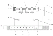
图1为本实用新型的基本结构示意图;Fig. 1 is the basic structure schematic diagram of the present utility model;
图2为本实用新型的图1中A处结构放大图;Fig. 2 is an enlarged view of the structure at place A in Fig. 1 of the present utility model;
图3为本实用新型的攻丝机构结构示意图;3 is a schematic structural diagram of a tapping mechanism of the present invention;
图4为本实用新型的攻丝组件结构示意图;4 is a schematic structural diagram of a tapping assembly of the present invention;
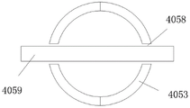
图5为本实用新型的弧板结构示意图。Figure 5 is a schematic diagram of the structure of the arc plate of the present invention.
具体实施方式Detailed ways
下面将结合本实用新型实施例中的附图,对本实用新型实施例中的技术方案进行清楚、完整地描述,显然,所描述的实施例仅仅是本实用新型一部分实施例,而不是全部的实施例。基于本实用新型中的实施例,本领域普通技术人员在没有做出创造性劳动前提下所获得的所有其他实施例,都属于本实用新型保护的范围。The technical solutions in the embodiments of the present utility model will be clearly and completely described below with reference to the accompanying drawings in the embodiments of the present utility model. Obviously, the described embodiments are only a part of the embodiments of the present utility model, rather than all the implementations. example. Based on the embodiments of the present invention, all other embodiments obtained by those of ordinary skill in the art without creative work fall within the protection scope of the present invention.
在本实用新型的描述中,需要理解的是,术语“中心”、“纵向”、“横向”、“长度”、“宽度”、“厚度”、“上”、“下”、“前”、“后”、“左”、“右”、“竖直”、“水平”、“顶”、“底”、“内”、“外”、“顺时针”、“逆时针”等指示的方位或位置关系为基于附图所示的方位或位置关系,仅是为了便于描述本实用新型和简化描述,而不是指示或暗示所指的设备或元件必须具有特定的方位、以特定的方位构造和操作,因此不能理解为对本实用新型的限制。In the description of the present invention, it should be understood that the terms "center", "longitudinal", "lateral", "length", "width", "thickness", "upper", "lower", "front", "Back", "Left", "Right", "Vertical", "Horizontal", "Top", "Bottom", "Inner", "Outer", "Clockwise", "Counterclockwise" etc. Or the positional relationship is based on the orientation or positional relationship shown in the accompanying drawings, which is only for the convenience of describing the present invention and simplifying the description, rather than indicating or implying that the referred device or element must have a specific orientation, be constructed in a specific orientation and operation, so it cannot be construed as a limitation to the present invention.
如图1-图5所示,本实用新型提供的一种攻丝机,包括底座1,底座1的顶部右侧固定连接有伸缩气缸2,伸缩气缸2的顶部固定连接有连接板3,连接板3的底部固定连接有第一挡板5和第二挡板6,第一挡板5的左侧固定连接有第一连接杆7,第二挡板6的右侧开设有放置槽8,放置槽8的内部底侧固定连接有第一弹簧9,第一弹簧9的顶部固定连接有滑块10,滑块10滑动连接于放置槽8的内部,滑块10的右侧固定连接有第二连接杆11,第二连接杆11的右侧底部固定连接有限位杆12,第一连接杆7的左侧底部开设有限位槽13,限位杆12位于限位槽13的内部,第一连接杆7的外表面套接有多组攻丝机构4,攻丝机构4包括套接于第一连接杆7外表面的移动块401,移动块401的顶部开设有螺纹槽402,螺纹槽402的内部螺纹连接有固定螺栓403,移动块401的底部固定连接有第一电机404,第一电机404的输出端固定连接有攻丝组件405;根据工件的攻丝要求调节攻丝机构4的间隔和数量,需要增加或者减少攻丝机构4时,向下按动第二连接杆11使第一弹簧9收缩,此时限位杆12从限位槽13内脱离,即可将攻丝机构4卸下或增加攻丝机构4,可以针对不同的攻丝要求进行攻丝,启动伸缩气缸2向下推动攻丝机构4使攻丝组件405对工件进行攻丝作业即可。As shown in Figures 1 to 5, a tapping machine provided by the present invention includes a
攻丝组件405包括支撑板4051,支撑板4051的底部开设有滑槽4052,滑槽4052的内部分别滑动连接有两组相对应的弧板4053,两组弧板4053之间放置有攻丝头,弧板4053的前后两端均固定连接有固定板4054,固定板4054的正面开设有穿孔4055,穿孔4055的内部放置有限位螺栓4056,限位螺栓4056的外表面螺纹连接有固定螺母4057;在需要更换攻丝头时,拧转固定螺母4057使其不再与固定板4054抵触,即可将两组弧板4053向两侧移动,从而可以对攻丝头进行更换,为工作人员带来一定的便利。The
弧板4053的外侧开设有定位槽4058,定位槽4058的内部螺纹连接有插杆4059;将插杆4059穿过定位槽4058和攻丝头的通孔中,可以对攻丝头进行初步固定,提高一定的固定效果。A
底座1的底部开设有置物槽14,置物槽14位于伸缩气缸2的左侧,置物槽14的内部转动连接有丝杆15,丝杆15的外表面螺纹连接有移块16,移块16的顶部固定连接有工作台17,底座1的左侧固定连接有第二电机18,第二电机18的输出端通过联轴器与丝杆15固定连接;将工件放置在工作台17上,然后启动第二电机18转动丝杆15使移块16带动工作台17移动至合适位置,适用于不同规格的工件。The bottom of the
工作台17顶部的左右两侧均固定连接有伸缩杆19,两组伸缩杆19的内侧均固定连接有定位板20;通过伸缩杆19推动定位板20,使两组定位板20对工件进行夹持固定,提高了本装置的攻丝效果。The left and right sides of the top of the
工作原理:首先将工件放置在工作台17上,然后启动第二电机18转动丝杆15使移块16带动工作台17移动至合适位置,再通过伸缩杆19推动定位板20,使两组定位板20对工件进行夹持固定,可以针对不同规格的工件进行使用,然后根据工件的攻丝要求调节攻丝机构4的间隔和数量,需要增加或者减少攻丝机构4时,向下按动第二连接杆11使第一弹簧9收缩,此时限位杆12从限位槽13内脱离,即可将攻丝机构4卸下或增加攻丝机构4,可以针对不同的攻丝要求进行攻丝,启动伸缩气缸2向下推动攻丝机构4使攻丝组件405对工件进行攻丝作业即可,在需要更换攻丝头时,首先插杆4059从定位槽4058和攻丝头的通孔中取出,然后拧转固定螺母4057使其不再与固定板4054抵触,即可将两组弧板4053向两侧移动,从而可以对攻丝头进行更换,为工作人员带来一定的便利。Working principle: first place the workpiece on the
以上显示和描述了本实用新型的基本原理、主要特征和本实用新型的优点。本行业的技术人员应该了解,本实用新型不受上述实施例的限制,上述实施例和说明书中描述的仅为本实用新型的优选例,并不用来限制本实用新型,在不脱离本实用新型精神和范围的前提下,本实用新型还会有各种变化和改进,这些变化和改进都落入要求保护的本实用新型范围内。本实用新型要求保护范围由所附的权利要求书及其等效物界定。The basic principles, main features and advantages of the present invention have been shown and described above. Those skilled in the art should understand that the present invention is not limited by the above-mentioned embodiments. The above-mentioned embodiments and descriptions are only preferred examples of the present invention and are not intended to limit the present invention. Under the premise of the spirit and scope, the present invention will have various changes and improvements, and these changes and improvements all fall within the scope of the claimed invention. The claimed scope of the present invention is defined by the appended claims and their equivalents.
Claims (5)
Priority Applications (1)
| Application Number | Priority Date | Filing Date | Title |
|---|---|---|---|
| CN202220287212.2U CN217316261U (en) | 2022-02-14 | 2022-02-14 | Tapping machine |
Applications Claiming Priority (1)
| Application Number | Priority Date | Filing Date | Title |
|---|---|---|---|
| CN202220287212.2U CN217316261U (en) | 2022-02-14 | 2022-02-14 | Tapping machine |
Publications (1)
| Publication Number | Publication Date |
|---|---|
| CN217316261U true CN217316261U (en) | 2022-08-30 |
Family
ID=82997540
Family Applications (1)
| Application Number | Title | Priority Date | Filing Date |
|---|---|---|---|
| CN202220287212.2U Active CN217316261U (en) | 2022-02-14 | 2022-02-14 | Tapping machine |
Country Status (1)
| Country | Link |
|---|---|
| CN (1) | CN217316261U (en) |
-
2022
- 2022-02-14 CN CN202220287212.2U patent/CN217316261U/en active Active
Similar Documents
| Publication | Publication Date | Title |
|---|---|---|
| CN221809125U (en) | Positioning device for bench drill | |
| CN111229883A (en) | Plate bending machine | |
| CN216442379U (en) | Fixing clamp convenient to adjust for machine manufacturing | |
| CN214109633U (en) | A multifunctional fixture for mechanical production and processing | |
| CN221870390U (en) | Motor bearing end cover drilling positioning device | |
| CN207982471U (en) | A kind of Manual tapping machine | |
| CN216542114U (en) | A processing platform for hardware fitting numerical control processing | |
| CN218837405U (en) | Positioning fixture for hardware machining with rapidly replaced chuck | |
| CN217913357U (en) | Numerical control plasma cutting machine of quick location | |
| CN216462092U (en) | A sheet metal cutting and clamping device | |
| CN216324320U (en) | Bending device for elevator machining | |
| CN211867596U (en) | Part frock clamp | |
| CN211990938U (en) | Multi-point supporting and pressing vehicle clamp for elevator base | |
| CN219169805U (en) | Tapping machine with stable positioning | |
| CN217620163U (en) | Clamp for machining motorcycle accessories | |
| CN221716283U (en) | A self-drilling screw processing positioning device | |
| CN221849444U (en) | A positioning device for lathe processing | |
| CN216940215U (en) | Machining device | |
| CN221870021U (en) | Auxiliary support device for bending machine | |
| CN221675587U (en) | Auxiliary positioning tool for bending machine | |
| CN221911836U (en) | Milling tool for metal parts | |
| CN221872144U (en) | Cutting mechanism for guide plate production | |
| CN221966971U (en) | Wire cutting clamp for die manufacturing | |
| CN217890230U (en) | Thin wall axle sleeve tapping processing location frock | |
| CN216461945U (en) | A drilling mechanism for hardware processing |
Legal Events
| Date | Code | Title | Description |
|---|---|---|---|
| GR01 | Patent grant | ||
| GR01 | Patent grant | ||
| PE01 | Entry into force of the registration of the contract for pledge of patent right | ||
| PE01 | Entry into force of the registration of the contract for pledge of patent right |
Denomination of utility model: A tapping machine Granted publication date: 20220830 Pledgee: Bengbu technology finance sub branch of Huishang Bank Co.,Ltd. Pledgor: Anhui Rooney New Material Technology Co.,Ltd. Registration number: Y2025980000300 |