Pipe end mechanism
Technical Field
The utility model relates to the field of machining, especially, relate to a pipe end mechanism.
Background
At present, a pipe end mechanism on the market generally only has one punch, and the end of a pipe fitting such as a copper pipe can be punched and shaped (for example, hole expansion or necking) through the punching action of the punch, and the existing pipe end machine has the following technical problems in the actual production process: foretell pipe-end machine once can only punch the pipe fitting of a model, if the pipe fitting of the different models of needs punching press, then need dismantle original drift, install required drift again, troublesome poeration, this production efficiency who just leads to pipe-end machine is low, and especially, when the pipe fitting of the multiple different models of punching press, foretell problem is especially salient.
In order to solve the above problems, the applicant has invented a multi-punch pipe end mechanism, which can be referred to with the following publication: CN 211464373U, invention name: the utility model provides a rotary die change device of pipe-end machine, this scheme adopts the mode of carousel to realize the retooling of drift, convenient to use, but the structure of carousel makes this mechanism whole bulky, and parts machining is with high costs for manufacturing cost is high.
Disclosure of Invention
The utility model aims at providing a compact structure, simple to operate, low in manufacturing cost's pipe end mechanism.
In order to achieve the above purpose, the utility model adopts the following technical scheme:
the utility model aims at providing a pipe end mechanism, including removing seat, drift station and the tight station of clamp, on removing the seat, be provided with a plurality of drifts side by side along the moving direction who removes the seat, remove the seat and be used for removing and carry the drift to the drift station, press from both sides tight station setting on the route of the punching press direction of drift station, press from both sides tight station and be used for pressing from both sides tight pipe fitting to supply the tip of the drift punching press pipe fitting on the drift station.
Preferably, the punch is a necking die, and the necking calibers of different punches are different.
Preferably, the punching head device further comprises a base, a first driving device, a second driving device and a connecting seat, the connecting seat is movably mounted on the base, the moving seat is movably mounted on the connecting seat, the first driving device is mounted on the base and connected with the connecting seat, the second driving device is mounted on the connecting seat and connected with the moving seat, the second driving device is used for driving the moving seat to enable the moving seat to convey the punching head to the punching head station, and the first driving device is used for driving the connecting seat to enable the punching head on the punching head station to be far away from or close to the end portion of the pipe fitting along the punching direction.
Preferably, the clamping device further comprises an upper clamping die and a lower clamping die, and the clamping station is formed between the upper clamping die and the lower clamping die.
Preferably, the lower clamping die is mounted on the base, and the upper clamping die is movably mounted on the base.
Preferably, the clamping device further comprises a third driving device, the third driving device is mounted on the base and connected with the upper clamping die to drive the upper clamping die to be close to or far away from the lower clamping die.
Preferably, a mandrel is installed in the cavity of the necking die.
Preferably, at least 2 punches are provided.
The utility model has the advantages that:
the utility model provides a pipe end mechanism through the arrangement that changes a plurality of drifts, makes a plurality of drifts set up side by side along the moving direction who removes the seat on removing the seat, and a plurality of drifts specifically are vertical range to make the overall structure of pipe end mechanism compacter, remove the seat shape moreover and be the design of cube, it is convenient to make, and the material use amount is few, can effectively reduce manufacturing cost, and it is more convenient to remove the installation of seat and drift.
Drawings
Fig. 1 is a schematic structural diagram of a pipe end mechanism provided by the present invention;
fig. 2 is a schematic structural view of the pipe end mechanism processing principle provided by the present invention;
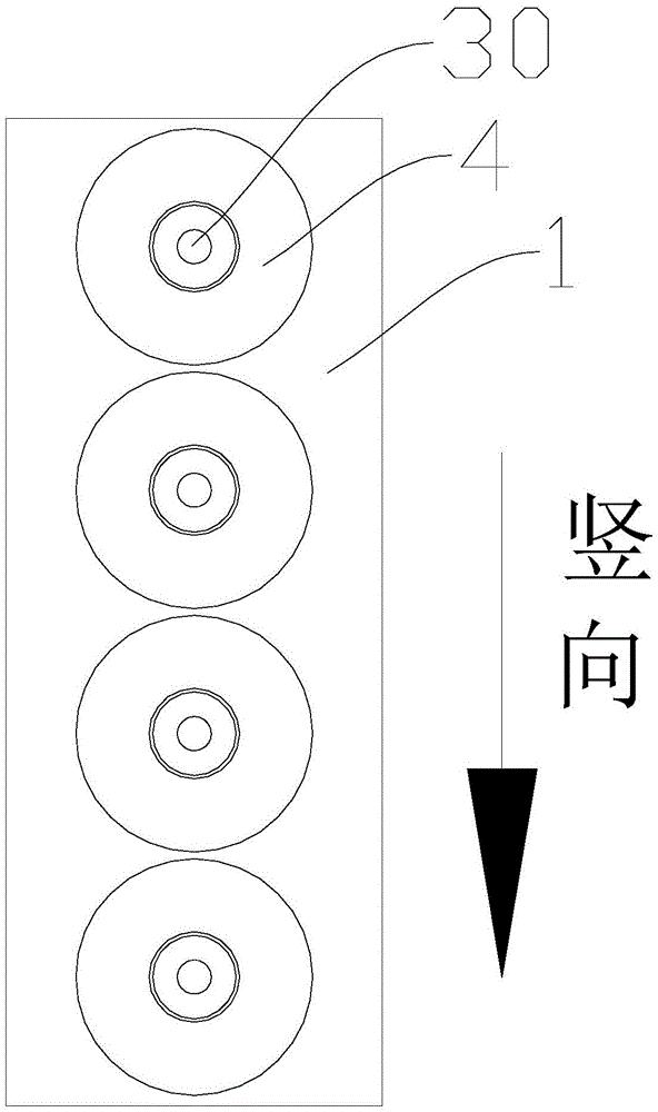
fig. 3 is a schematic structural view of the right side projection of the movable seat and the punch provided by the present invention;
fig. 4 is a schematic structural diagram of another state of the pipe end mechanism provided by the present invention.
Detailed Description
In order to make the objects, technical solutions and advantages of the embodiments of the present invention clearer, the embodiments of the present invention will be clearly and completely described below with reference to the accompanying drawings in the embodiments of the present invention, and it is obvious that the described embodiments are some, but not all, embodiments of the present invention. Based on the embodiments in the present invention, all other embodiments obtained by a person skilled in the art without creative efforts all belong to the protection scope of the present invention.
As shown in fig. 1 to 3, the present embodiment provides a pipe end mechanism, which includes a moving seat 1, a punch station 2 and a clamping station 3, wherein a plurality of side-by-side punches 4 are arranged on the moving seat 1 along a moving direction of the moving seat 1, the moving seat 1 is used for moving and conveying the punches 4 to the punch station 2, the clamping station 3 is arranged on a path of a punching direction of the punch station 2, and the clamping station 3 is used for clamping a pipe 40 so that the punches 4 on the punch station 2 punch an end of the pipe 40; the arrangement mode of the plurality of punches 4 is changed, so that the plurality of punches 4 are arranged on the movable seat 1 side by side along the moving direction of the movable seat 1, the plurality of punches 4 are vertically arranged, the integral structure of the pipe end mechanism is more compact, the movable seat 1 is in a square design, the manufacturing is convenient, the material usage amount is small, the manufacturing cost can be effectively reduced, and the movable seat 1 and the punches 4 are more convenient to install; wherein, the number of the punch heads 4 is at least 2, in this embodiment, the number of the punch heads 4 is 4, and the number of the punch heads 4 can be designed according to actual production requirements.
The punch 4 is a necking die, and the necking calibers of different punches 4 are different; specifically, the reducing calibers of the punches 4 are arranged in a descending order from top to bottom along the moving direction of the moving seat 1; during the use, carry required drift 4 to drift station 2 through removing seat 1, can realize that this drift 4 carries out the punching press plastic to the tip of pressing from both sides pipe fitting 40 on the station 3, when needs use different drift 4, through the removal of removing seat 1, can switch to the punching press station corresponding drift 4, make this drift 4 can carry out the plastic punching press to the tip of pressing from both sides pipe fitting 40 on the station 3 the utility model provides an among the pipe end mechanism, realized the rotation of each drift 4 through removing the setting of seat 1 and switched, with the punching press needs to different pipe fittings 40, easy operation, convenient to use has promoted production efficiency effectively, does benefit to the mass production of multiple different model pipe fittings 40.
As shown in fig. 4, the pipe end mechanism further includes a base 5, a first driving device 6, a second driving device 7 and a connecting base 8, the connecting base 8 is movably mounted on the base 5 through a sliding rail assembly, the moving base 1 is movably mounted on the connecting base 8 through a sliding rail assembly, the first driving device 6 is mounted on the base 5 and connected with the connecting base 8, the second driving device 7 is mounted on the connecting base 8 and connected with the moving base 1, the second driving device 7 is used for driving the moving base 1, so that the moving base 1 conveys the punch 4 to the punch station 2, the first driving device 6 is used for driving the connecting base 8, so that the punch 4 on the punch station 2 is far away from or close to the end of the pipe 40 along the punching direction, and the pipe end mechanism has simple structure, simple transmission mode and convenient assembly; in this embodiment, the first driving device 6 is a cylinder, the second driving device 7 is a motor screw module, and the motor screw module is used to facilitate gradual control of the moving distance of the punch 4 when the punch 4 is replaced, so as to improve the control precision.
As shown in fig. 4, the pipe end mechanism further includes a third driving device 20, an upper clamping die 9 and a lower clamping die 10, and the clamping station 3 is formed between the upper clamping die 9 and the lower clamping die 10; the lower clamping die 10 is mounted on the base 5, and the upper clamping die 9 is movably mounted on the base 5 through a sliding block assembly; the third driving device 20 is installed on the base 5 and connected with the upper clamping die 9, and is used for driving the upper clamping die 9 to be close to or far away from the lower clamping die 10, when the third driving device 20 drives the upper clamping die 9 to be close to the lower clamping die 10, the upper clamping die 9 and the lower clamping die 10 can clamp the pipe fitting 40, the structure is simple, the pipe end machining function and the clamping function are integrated, the pipe end mechanism can be conveniently moved in a whole renting mode in the later period, the punch station 2 and the clamping station 3 do not need to be aligned again after moving, and the use is convenient; in the present embodiment, the third driving device 20 is a cylinder.
As shown in fig. 2 and fig. 3, in this embodiment, the mandrel 30 is installed in the cavity 41 of the necking die, and the mandrel 30 is arranged to prevent the necking transition of the tube end of the tube 40 and ensure that the inner diameter of the tube 40 meets the production requirement; in practice, the necking of the end of the tube 40 may be performed without the mandrel 30, depending on the manufacturing requirements.
It should be noted that all the directional indicators (such as "up", "down", "front", "back", "vertical", etc.) in the embodiments of the present invention are only used to explain the relative position relationship between the components, the movement situation, etc. in a specific posture (as shown in the drawings), and if the specific posture is changed, the directional indicator is changed accordingly.
In the present application, unless expressly stated or limited otherwise, the terms "connected" and "fixed" are to be construed broadly, e.g., "fixed" may be fixedly connected or detachably connected, or integrally formed; "connected" may be mechanically or electrically connected; they may be directly connected or indirectly connected through intervening media, or they may be interconnected within two elements or in a relationship where two elements interact with each other unless otherwise specifically limited. The specific meaning of the above terms in the present invention can be understood according to specific situations by those skilled in the art.
Various other modifications and changes may be made by those skilled in the art based on the above-described technical solutions and concepts, and all such modifications and changes are intended to fall within the scope of the claims.