CN217311055U - Traditional Chinese Medicine Electronic Combination Therapy Machine - Google Patents
Traditional Chinese Medicine Electronic Combination Therapy Machine Download PDFInfo
- Publication number
- CN217311055U CN217311055U CN202220305676.1U CN202220305676U CN217311055U CN 217311055 U CN217311055 U CN 217311055U CN 202220305676 U CN202220305676 U CN 202220305676U CN 217311055 U CN217311055 U CN 217311055U
- Authority
- CN
- China
- Prior art keywords
- fixedly connected
- installation box
- worm
- rod
- chinese medicine
- Prior art date
- Legal status (The legal status is an assumption and is not a legal conclusion. Google has not performed a legal analysis and makes no representation as to the accuracy of the status listed.)
- Expired - Fee Related
Links
- 238000002648 combination therapy Methods 0.000 title claims abstract description 19
- 239000003814 drug Substances 0.000 title claims abstract description 19
- 229940079593 drug Drugs 0.000 title 1
- 238000009434 installation Methods 0.000 claims abstract description 54
- 210000003141 lower extremity Anatomy 0.000 abstract description 16
- 230000017531 blood circulation Effects 0.000 abstract description 2
- 210000003205 muscle Anatomy 0.000 abstract description 2
- 238000010586 diagram Methods 0.000 description 7
- 230000000694 effects Effects 0.000 description 2
- 238000000034 method Methods 0.000 description 2
- 230000006837 decompression Effects 0.000 description 1
- 230000007547 defect Effects 0.000 description 1
- 230000001934 delay Effects 0.000 description 1
- 201000010099 disease Diseases 0.000 description 1
- 208000037265 diseases, disorders, signs and symptoms Diseases 0.000 description 1
- 238000005516 engineering process Methods 0.000 description 1
- 230000002349 favourable effect Effects 0.000 description 1
- 238000012986 modification Methods 0.000 description 1
- 230000004048 modification Effects 0.000 description 1
- 238000000554 physical therapy Methods 0.000 description 1
- 238000011084 recovery Methods 0.000 description 1
- 239000013589 supplement Substances 0.000 description 1
- 238000002560 therapeutic procedure Methods 0.000 description 1
Images




Landscapes
- Massaging Devices (AREA)
Abstract
中医电子组合理疗机,底板的上端安装有可升降的安装盒,安装盒的前后两端分别安装有可调节高度的支撑板,安装盒上端表面的左右两侧分别转动连接有可同步转动的转动板,转动板的上端左侧分别安装有多个按摩球;本装置在使用时可以将患者的下肢放置在安装盒的上侧,通过支撑板支撑后通过转动按转动带动按摩球向内侧对患者的下肢进行充分的挤压按摩,缓解患者下肢的肌肉,促进血液循环,并且安装盒可以根据患者的需要进行调节高度以及倾斜度,加强本装置使用时的舒适度,并且操作简单方便。

The traditional Chinese medicine electronic combination therapy machine, the upper end of the base plate is installed with a lifting installation box, the front and rear ends of the installation box are respectively installed with height-adjustable support plates, and the left and right sides of the upper surface of the installation box are respectively connected to rotate synchronously. A plurality of massage balls are installed on the left side of the upper end of the rotating plate; when the device is in use, the lower limbs of the patient can be placed on the upper side of the installation box, supported by the support plate, and then rotated and driven to drive the massage balls to the inside of the patient. The lower limbs of the device can be fully squeezed and massaged to relieve the muscles of the lower limbs of the patient and promote blood circulation, and the installation box can adjust the height and inclination according to the needs of the patient, which enhances the comfort of the device when using, and the operation is simple and convenient.
Description
技术领域technical field
本实用新型属于医用器材领域,具体涉及中医电子组合理疗机。The utility model belongs to the field of medical equipment, in particular to a traditional Chinese medicine electronic combination therapy machine.
背景技术Background technique
理疗就是利用人工或自然界物理因素作用于人体,使之产生有利的反应,达到预防和治疗疾病目的的方法,是康复治疗的重要内容,在对下肢功能性障碍的患者进行康复治疗时,对下肢进行充分的按摩可以有效的促使下肢的恢复,目前在帮助患者的下肢进行康复锻炼时通常以人工按摩为主,较为费力,并且容易耽误医护人员的其他工作。Physiotherapy is the use of artificial or natural physical factors to act on the human body to produce a favorable response to achieve the purpose of preventing and treating diseases. It is an important content of rehabilitation therapy. Sufficient massage can effectively promote the recovery of the lower extremities. At present, when helping patients with lower extremity rehabilitation exercises, manual massage is usually the main method, which is labor-intensive and easily delays other work of medical staff.
实用新型内容Utility model content
针对上述情况,为克服现有技术的缺陷,本实用新型提供了中医电子组合理疗机,有效的解决了上述背景技术中所提到的问题。In view of the above situation, in order to overcome the defects of the prior art, the present invention provides a traditional Chinese medicine electronic combination therapy machine, which effectively solves the problems mentioned in the above background technology.
为解决上述问题本实用新型所采取的技术方案是:The technical scheme adopted by the present utility model for solving the above-mentioned problems is:
中医电子组合理疗机,包括底板,所述底板的上端安装有可升降的安装盒,所述安装盒的前后两端分别安装有可调节高度的支撑板,所述安装盒上端表面的左右两侧分别转动连接有可同步转动的转动板,左右两侧的所述转动板的转动方向彼此相反,所述转动板的上端左侧分别安装有多个按摩球,所述按摩球分别均匀的竖直排列,所述按摩球下端分别转动连接有连接架,所述连接架的内侧分别与所述转动板表面滑动连接,所述连接架的内端分别固定连接有阻力弹簧,所述阻力弹簧的另一端分别与所述转动板固定连接。The traditional Chinese medicine electronic combination therapy machine includes a base plate, the upper end of the base plate is installed with a lifting installation box, the front and rear ends of the installation box are respectively installed with height-adjustable support plates, and the left and right sides of the upper surface of the installation box are installed. Rotating plates that can be rotated synchronously are respectively connected in rotation, the rotation directions of the rotating plates on the left and right sides are opposite to each other, and a plurality of massage balls are respectively installed on the left side of the upper end of the rotating plate, and the massage balls are evenly vertical Arrangement, the lower ends of the massage balls are respectively connected with connecting frames in rotation, the inner sides of the connecting frames are respectively slidably connected with the surface of the rotating plate, the inner ends of the connecting frames are respectively fixedly connected with resistance springs, and the other sides of the resistance springs are respectively connected. One end is respectively fixedly connected with the rotating plate.
优选的,所述转动板的上端左侧分别开设有多个横向均匀排列的连接滑槽,所述连接滑槽内部分别滑动连接有连接滑块,所述阻力弹簧分别设置在所述连接滑块的内侧,所述连接架的内端分别与下侧的所述连接滑块固定连接。Preferably, a plurality of horizontally evenly arranged connecting chutes are respectively provided on the left side of the upper end of the rotating plate, and connecting sliding blocks are respectively slidably connected inside the connecting sliding grooves, and the resistance springs are respectively arranged on the connecting sliding blocks. The inner ends of the connecting frames are respectively fixedly connected with the connecting sliders on the lower side.
优选的,所述安装盒的内部分别设置有多个沿着所述安装盒的长度方向排列的第三蜗杆,多个所述第三蜗杆相互固定连接,前后两侧的所述第三蜗杆分别与所述安装盒内壁转动连接,前侧的所述第三蜗杆的前端固定连接有配合齿轮,所述配合齿轮的上侧啮合有驱动齿轮,所述驱动齿轮的前侧固定连接有电机,所述电机与所述安装盒固定连接;所述第三蜗杆的下侧分别啮合有第三蜗轮,所述第三蜗轮的中部分别固定连接有第三连动杆,所述第三连动杆与所述安装盒内壁转动连接,所述第三连动杆的左右两端分别固定连接有第一换向锥齿轮,所述第一换向锥齿轮的上侧分别啮合有第二换向锥齿轮,所述第二换向锥齿轮分别与所述转动板同轴心固定连接。Preferably, the interior of the installation box is provided with a plurality of third worms arranged along the length direction of the installation box, the plurality of third worms are fixedly connected to each other, and the third worms on the front and rear sides are respectively It is rotatably connected with the inner wall of the installation box, the front end of the third worm on the front side is fixedly connected with a matching gear, the upper side of the matching gear is meshed with a driving gear, and the front side of the driving gear is fixedly connected with a motor, so The motor is fixedly connected with the installation box; the lower side of the third worm is meshed with a third worm wheel respectively, and the middle part of the third worm wheel is respectively fixedly connected with a third link rod, and the third link rod is connected with the third worm wheel. The inner wall of the installation box is rotatably connected, the left and right ends of the third linkage rod are respectively fixedly connected with a first reversing bevel gear, and the upper side of the first reversing bevel gear is respectively meshed with a second reversing bevel gear , the second reversing bevel gears are respectively coaxially and fixedly connected with the rotating plate.
优选的,所述支撑板的下端分别固定连接有移动槽板,所述移动槽板的表面开设有矩形槽,所述矩形槽的内侧滑动连接有连接块,所述连接块与所述安装盒表面固定连接,所述连接块的外端分别固定连接有连接螺杆,所述连接螺杆的表面分别通过螺纹连接有固定旋钮。Preferably, moving groove plates are fixedly connected to the lower ends of the support plates respectively, a rectangular groove is formed on the surface of the moving groove plate, and a connecting block is slidably connected to the inner side of the rectangular groove, and the connecting block is connected to the installation box. The surfaces are fixedly connected, the outer ends of the connecting blocks are respectively fixedly connected with connecting screws, and the surfaces of the connecting screws are respectively connected with fixed knobs through threads.
优选的,所述底板上端右侧的前后两侧分别铰接有平行杆,两个所述平行杆的下侧同轴心固定连接有一个第二连动杆,所述第二连动杆的表面固定连接有第一蜗轮,所述第一蜗轮的上侧啮合有第一蜗杆,所述第一蜗杆与所述底板上端转动连接,所述第一蜗杆的前端固定连接有第一旋钮;所述底板上端左侧的前后两侧分别铰接有第一铰接杆,所述第一铰接杆的上端分别固定连接有第一连动杆,所述第一连动杆的前后两侧分别铰接有第二铰接杆,所述第二铰接杆的上端与所述安装盒底部铰接;所述第一连动杆的前端固定连接有第二蜗轮,所述第二蜗轮的表面啮合有第二蜗杆,所述第二蜗杆前侧的所述第二铰接杆表面转动连接,所述第二蜗杆的下端固定连接有第二旋钮。Preferably, parallel rods are hinged on the front and rear sides of the right side of the upper end of the bottom plate respectively, and a second linkage rod is fixedly connected to the lower sides of the two parallel rods coaxially. A first worm wheel is fixedly connected, the upper side of the first worm wheel is engaged with a first worm, the first worm is rotatably connected with the upper end of the bottom plate, and the front end of the first worm is fixedly connected with a first knob; the The front and rear sides of the left side of the upper end of the bottom plate are respectively hinged with first hinge rods, the upper ends of the first hinge rods are respectively fixedly connected with first link rods, and the front and rear sides of the first link rods are hinged with second hinge rods respectively. A hinge rod, the upper end of the second hinge rod is hinged with the bottom of the installation box; the front end of the first link rod is fixedly connected with a second worm wheel, the surface of the second worm wheel is engaged with a second worm, the The surface of the second hinge rod on the front side of the second worm is rotatably connected, and the lower end of the second worm is fixedly connected with a second knob.
优选的,所述第一铰接杆和所述底板铰接点距第二铰接杆与安装盒的铰接点的距离与所述平行杆上下两端的连接点的长度相等。Preferably, the distance from the hinge point of the first hinge rod and the bottom plate to the hinge point of the second hinge rod and the installation box is equal to the length of the connection points of the upper and lower ends of the parallel rod.
本实用新型结构新颖,构思巧妙,操作简单方便,和现有技术相比具有以下优点:The utility model has novel structure, ingenious design, simple and convenient operation, and has the following advantages compared with the prior art:
本装置在使用时可以将患者的下肢放置在安装盒的上侧,通过支撑板支撑后通过转动按转动带动按摩球向内侧对患者的下肢进行充分的挤压按摩,缓解患者下肢的肌肉,促进血液循环,并且安装盒可以根据患者的需要进行调节高度以及倾斜度,加强本装置使用时的舒适度,并且操作简单方便。When the device is in use, the patient's lower limb can be placed on the upper side of the installation box. After being supported by the support plate, the massage ball can be rotated inward to fully squeeze and massage the patient's lower limb, so as to relieve the muscles of the patient's lower limb and promote Blood circulation, and the installation box can be adjusted in height and inclination according to the needs of the patient, so as to enhance the comfort when the device is used, and the operation is simple and convenient.
附图说明Description of drawings
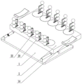
图1为本实用新型的中医电子组合理疗机的整体结构示意图。1 is a schematic diagram of the overall structure of the traditional Chinese medicine electronic combination therapy machine of the present invention.
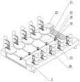
图2为本实用新型的中医电子组合理疗机的安装盒升降结构第一示意图。2 is a first schematic diagram of the lifting structure of the installation box of the electronic combination therapy machine of traditional Chinese medicine of the present invention.
图3为本实用新型的中医电子组合理疗机的安装盒升降结构第二示意图。3 is a second schematic diagram of the lifting structure of the installation box of the electronic combination therapy machine of traditional Chinese medicine of the present invention.
图4为本实用新型的中医电子组合理疗机的支撑板安装结构示意图。FIG. 4 is a schematic diagram of the installation structure of the support plate of the traditional Chinese medicine electronic combination therapy machine of the present invention.
图5为本实用新型的中医电子组合理疗机的安装盒内部结构第一示意图。FIG. 5 is a first schematic diagram of the internal structure of the installation box of the traditional Chinese medicine electronic combination therapy machine of the present invention.
图6为本实用新型的中医电子组合理疗机的安装盒内部结构第二示意图。FIG. 6 is a second schematic diagram of the internal structure of the installation box of the traditional Chinese medicine electronic combination therapy machine of the present invention.
图7为本实用新型的中医电子组合理疗机的按摩球安装结构示意图。FIG. 7 is a schematic diagram of the installation structure of the massage ball of the traditional Chinese medicine electronic combination therapy machine of the present invention.
图中:1-底板、2-安装盒、3-平行杆、4-第一铰接杆、5-第二铰接杆、6-第一连动杆、7-第二连动杆、8-第一蜗轮、9-第一蜗杆、10-第一旋钮、11-第二蜗轮、12-第二蜗杆、13-第二旋钮、14-支撑板、15-移动槽板、16-连接块、17-连接螺杆、18-固定旋钮、19-电机、20-驱动齿轮、21-第三连动杆、22-第三蜗轮、23-第三蜗杆、24-配合齿轮、25-转动板、26-第一换向锥齿轮、27-第二换向锥齿轮、28-按摩球、29-连接架、30-连接滑块、31-阻力弹簧。In the figure: 1-base plate, 2-installation box, 3-parallel rod, 4-first hinge rod, 5-second hinge rod, 6-first link rod, 7-second link rod, 8-th A worm gear, 9-first worm, 10-first knob, 11-second worm gear, 12-second worm, 13-second knob, 14-support plate, 15-moving groove plate, 16-connecting block, 17 -connecting screw, 18-fixed knob, 19-motor, 20-drive gear, 21-third linkage rod, 22-third worm gear, 23-third worm, 24-matching gear, 25-rotating plate, 26- First reversing bevel gear, 27-second reversing bevel gear, 28-massage ball, 29-connecting frame, 30-connecting slider, 31-resistance spring.
具体实施方式Detailed ways
以下是本实用新型的具体实施例,并结合附图对本实用新型的技术方案作进一步的描述,但本实用新型并不限于这些实施例。The following are specific embodiments of the present utility model, and the technical solutions of the present utility model are further described in conjunction with the accompanying drawings, but the present utility model is not limited to these embodiments.
如图1-7所示,本实用新型提供中医电子组合理疗机,包括底板1,所述底板1的上端安装有可升降的安装盒2,所述安装盒2的前后两端分别安装有可调节高度的支撑板14,所述安装盒2上端表面的左右两侧分别转动连接有可同步转动的转动板25,左右两侧的所述转动板25的转动方向彼此相反,所述转动板25的上端左侧分别安装有多个按摩球28,所述按摩球28分别均匀的竖直排列,所述按摩球28下端分别转动连接有连接架29,所述连接架29的内侧分别与所述转动板25表面滑动连接,所述连接架29的内端分别固定连接有阻力弹簧31,所述阻力弹簧31的另一端分别与所述转动板25固定连接。As shown in Figures 1-7, the present utility model provides a traditional Chinese medicine electronic combination therapy machine, comprising a
所述转动板25的上端左侧分别开设有多个横向均匀排列的连接滑槽,所述连接滑槽内部分别滑动连接有连接滑块30,所述阻力弹簧31分别设置在所述连接滑块30的内侧,所述连接架29的内端分别与下侧的所述连接滑块30固定连接。The upper left side of the upper end of the
本装置在使用时可以将患者的下肢放置在安装盒2上端,并通过支撑板14进行支撑,下肢放置在安装盒2上端时通过带动左右两侧的转动板25同步转动便可以带动按摩球28同步向内侧转动对患者的下肢进行挤压按摩,起到对下肢按摩的效果,如图1和图7所示,在按摩球28同步向内侧转动对患者的下肢进行挤压时多个按摩球28可以根据患者下肢的形状进行不同程度的向内侧移动,加强使用者按摩时的舒适度,并且可以对患者的下肢部分进行充分的按摩,阻力弹簧31可以起到减压的作用,并且可以通过推动连接架29带动按摩球28复位;在进行按摩时安装盒2的高度可以根据使用者的需要进行调节。When the device is in use, the lower limbs of the patient can be placed on the upper end of the
所述安装盒2的内部分别设置有多个沿着所述安装盒2的长度方向排列的第三蜗杆23,多个所述第三蜗杆23相互固定连接,前后两侧的所述第三蜗杆23分别与所述安装盒2内壁转动连接,前侧的所述第三蜗杆23的前端固定连接有配合齿轮24,所述配合齿轮24的上侧啮合有驱动齿轮20,所述驱动齿轮20的前侧固定连接有电机19,所述电机19与所述安装盒2固定连接;所述第三蜗杆23的下侧分别啮合有第三蜗轮22,所述第三蜗轮22的中部分别固定连接有第三连动杆21,所述第三连动杆21与所述安装盒2内壁转动连接,所述第三连动杆21的左右两端分别固定连接有第一换向锥齿轮26,所述第一换向锥齿轮26的上侧分别啮合有第二换向锥齿轮27,所述第二换向锥齿轮27分别与所述转动板25同轴心固定连接。The interior of the
电机19用于带动多个转动板25同步转动,当电机19启动时通过驱动齿轮20和配合齿轮24的啮合下便可以带动前侧的第三蜗杆23进行转动,进而多个第三蜗杆23可以同步进行转动对第三蜗轮22进行啮合,进而带动第三连动杆21进行转动,并通过第一换向锥齿轮26和第二换向锥齿轮27的啮合下便可以带动转动板25进行转动。The
所述支撑板14的下端分别固定连接有移动槽板15,所述移动槽板15的表面开设有矩形槽,所述矩形槽的内侧滑动连接有连接块16,所述连接块16与所述安装盒2表面固定连接,所述连接块16的外端分别固定连接有连接螺杆17,所述连接螺杆17的表面分别通过螺纹连接有固定旋钮18。The lower ends of the
固定旋钮18用于对支撑板14进行固定,移动槽板15可以根据使用者的需求进行上下调节,移动槽板15用于支撑板14上下移动时为连接块16提供移动空间,在连接块16呈矩形结构,当矩形槽与连接块16滑动连接时移动槽板15便只能上下移动,进而通过转动固定旋钮18,通过与连接螺杆17螺纹连接的作用下便可以通过对移动槽板15的挤压实现对支撑板14的固定效果。The
所述底板1上端右侧的前后两侧分别铰接有平行杆3,两个所述平行杆3的下侧同轴心固定连接有一个第二连动杆7,所述第二连动杆7的表面固定连接有第一蜗轮8,所述第一蜗轮8的上侧啮合有第一蜗杆9,所述第一蜗杆9与所述底板1上端转动连接,所述第一蜗杆9的前端固定连接有第一旋钮10;所述底板1上端左侧的前后两侧分别铰接有第一铰接杆4,所述第一铰接杆4的上端分别固定连接有第一连动杆6,所述第一连动杆6的前后两侧分别铰接有第二铰接杆5,所述第二铰接杆5的上端与所述安装盒2底部铰接;所述第一连动杆6的前端固定连接有第二蜗轮11,所述第二蜗轮11的表面啮合有第二蜗杆12,所述第二蜗杆12前侧的所述第二铰接杆5表面转动连接,所述第二蜗杆12的下端固定连接有第二旋钮13。
所述第一铰接杆4和所述底板1铰接点距第二铰接杆5与安装盒2的铰接点的距离与所述平行杆3上下两端的连接点的长度相等。The distance between the hinge point of the
第一旋钮10用于控制安装盒2进行升降,当第一铰接杆4与第二铰接杆5保存平行时,在与平行杆3的配合下可以将安装盒2支撑为一个平面结构,并且第一铰接杆4与第二铰接杆5之间的连接存在第二蜗杆12与第二蜗轮11的限动,在不转动第二旋钮13时第一铰接杆4与第二铰接杆5之间便不能活动,进而通过在转动第一旋钮10带动第一蜗杆9转动时通过与第一蜗轮8的啮合便可以带动第二连动杆7转动,进而带动平行杆3摆动,第一铰接杆4和第二铰接杆5便会同步摆动,支撑安装盒2进行升降,当患者的下肢需要弯曲时可以通过转动第二旋钮13调节安装盒2的倾斜状态,通过转动第二旋钮13可以带动第二蜗杆12转动,并在第二蜗杆12与第二蜗轮11啮合的作用下便可以带动第一铰接杆4和第二铰接杆5之间进行弯折,然后便可以带动安装盒2的后侧进行上下摆动,实现对安装盒2倾斜角度的控制。The
本文中所描述的具体实施例仅仅是对本实用新型精神作举例说明。本实用新型所属技术领域的技术人员可以对所描述的具体实施例做各种各样的修改或补充或采用类似的方式代替,但并不会偏离本实用新型的精神或者超越所附权利要求书所定义的范围。The specific embodiments described herein are merely illustrative of the spirit of the present invention. Those skilled in the art to which the present invention pertains can make various modifications or supplements to the described specific embodiments or replace them in similar ways, but will not deviate from the spirit of the present invention or go beyond the appended claims the defined range.
Claims (6)
Priority Applications (1)
| Application Number | Priority Date | Filing Date | Title |
|---|---|---|---|
| CN202220305676.1U CN217311055U (en) | 2022-02-16 | 2022-02-16 | Traditional Chinese Medicine Electronic Combination Therapy Machine |
Applications Claiming Priority (1)
| Application Number | Priority Date | Filing Date | Title |
|---|---|---|---|
| CN202220305676.1U CN217311055U (en) | 2022-02-16 | 2022-02-16 | Traditional Chinese Medicine Electronic Combination Therapy Machine |
Publications (1)
| Publication Number | Publication Date |
|---|---|
| CN217311055U true CN217311055U (en) | 2022-08-30 |
Family
ID=82996566
Family Applications (1)
| Application Number | Title | Priority Date | Filing Date |
|---|---|---|---|
| CN202220305676.1U Expired - Fee Related CN217311055U (en) | 2022-02-16 | 2022-02-16 | Traditional Chinese Medicine Electronic Combination Therapy Machine |
Country Status (1)
| Country | Link |
|---|---|
| CN (1) | CN217311055U (en) |
-
2022
- 2022-02-16 CN CN202220305676.1U patent/CN217311055U/en not_active Expired - Fee Related
Similar Documents
| Publication | Publication Date | Title |
|---|---|---|
| CN111494160A (en) | Postoperative exercise device for thoracic surgery | |
| CN109646251B (en) | A device for leg movement of ICU patients | |
| CN111249121A (en) | A varicose vein rehabilitation training device for vascular surgery | |
| KR200475022Y1 (en) | Bed for moxibustion | |
| CN113633518B (en) | An exercise device for rehabilitation of bedridden patients | |
| CN111773011A (en) | Cerebrovascular disease treatment bed | |
| CN215607380U (en) | A pediatric clinical rehabilitation device with leg exercise function | |
| CN108030640B (en) | A neurological rehabilitation training device | |
| CN215461724U (en) | High-applicability limb stretching device for physical training | |
| CN211326280U (en) | Household portable sickbed | |
| CN210963013U (en) | Automatic multi-functional moxa-moxibustion chair of formula | |
| CN113197758A (en) | Massage device capable of carrying out physiotherapy on cervical spondylosis patient | |
| CN112451311B (en) | Cerebral apoplexy rehabilitation exercise device | |
| CN113116695B (en) | A device for promoting blood circulation for obstetrics and gynecology rehabilitation | |
| CN208031467U (en) | A kind of flexes training device | |
| CN219354435U (en) | Joint surgery nursing seat | |
| CN216570615U (en) | Foot protection frame for diabetes nursing | |
| CN112932921B (en) | A rehabilitation training device for gynaecology and obstetrics's nursing | |
| CN115844688A (en) | Bed rehabilitation device for leg rehabilitation | |
| CN216148530U (en) | Infant massage auxiliary assembly | |
| CN209075375U (en) | A kind of severe comatose patient limbs care device | |
| CN218923117U (en) | Lumbar vertebra treatment equipment for pain department | |
| CN114053055A (en) | Be used for paralysed patient to nurse massage bed of standing up by oneself | |
| CN114392530A (en) | Traditional Chinese medicine cardiovascular disease rehabilitation device | |
| CN219836079U (en) | Breast cancer postoperative rehabilitation exercise device |
Legal Events
| Date | Code | Title | Description |
|---|---|---|---|
| GR01 | Patent grant | ||
| GR01 | Patent grant | ||
| CF01 | Termination of patent right due to non-payment of annual fee | ||
| CF01 | Termination of patent right due to non-payment of annual fee |
Granted publication date: 20220830 |