CN217303794U - Size measuring device of inclined bearing seat - Google Patents
Size measuring device of inclined bearing seat Download PDFInfo
- Publication number
- CN217303794U CN217303794U CN202221139030.7U CN202221139030U CN217303794U CN 217303794 U CN217303794 U CN 217303794U CN 202221139030 U CN202221139030 U CN 202221139030U CN 217303794 U CN217303794 U CN 217303794U
- Authority
- CN
- China
- Prior art keywords
- bearing seat
- measuring
- base
- fixed
- measuring unit
- Prior art date
- Legal status (The legal status is an assumption and is not a legal conclusion. Google has not performed a legal analysis and makes no representation as to the accuracy of the status listed.)
- Active
Links
Images


Landscapes
- A Measuring Device Byusing Mechanical Method (AREA)
Abstract
本实用新型提供一种斜轴承座的尺寸测量装置,包括测量机构、限位机构;测量机构包括基座、第一测量单元、第二测量单元;基座上固定有斜轴承座;斜轴承座上固定有限位机构;限位机构的中心轴与斜轴承座同轴;第一测量单元和第二测量单元均固定在基座上,第一测量单元和第二测量单元分别测量限位机构中心轴的位置数据。本实用新型在斜轴承座的尺寸测量装置中设置有测量机构、限位机构,通过将限位机构的中心轴与斜轴承座设置为同轴,通过第一测量单元和第二测量单元分别测量出限位机构中心轴的位置数据即能得到斜轴承座的中心高度和中心宽度。
The utility model provides a dimension measuring device for an oblique bearing seat, which comprises a measuring mechanism and a limit mechanism; the measuring mechanism comprises a base, a first measuring unit and a second measuring unit; an oblique bearing seat is fixed on the base; The upper fixed limit mechanism; the center axis of the limit mechanism is coaxial with the inclined bearing seat; the first measurement unit and the second measurement unit are both fixed on the base, and the first measurement unit and the second measurement unit measure the center of the limit mechanism respectively Position data of the axis. The utility model is provided with a measuring mechanism and a limit mechanism in the dimension measuring device of the inclined bearing seat. The center height and center width of the inclined bearing seat can be obtained by outputting the position data of the center axis of the limit mechanism.
Description
技术领域technical field
本实用新型涉及玻璃自动化生产线技术领域,具体为一种斜轴承座的尺寸测量装置。The utility model relates to the technical field of glass automatic production lines, in particular to a dimension measuring device of an inclined bearing seat.
背景技术Background technique
在玻璃生产线上,退火窑辊道输送是很关键的一项工作,其中辅助传动装置的斜轴承座加工精度又是重点;斜轴承座中心高度及中心宽度的尺寸误差,直接影响安装时的齿轮间啮合,从而影响传动装置的稳定性,导致辊道输送无法正常工作。In the glass production line, the roller conveying of the annealing kiln is a very critical task, in which the machining accuracy of the inclined bearing seat of the auxiliary transmission device is the key point; the dimensional error of the center height and center width of the inclined bearing seat directly affects the gear during installation. Intermeshing, thus affecting the stability of the transmission, resulting in the roller conveyor can not work properly.
以往此类轴承座脱离机床等加工设备后,无法确定轴承座的中心高度及中心宽度,只能通过基础量具对其进行大致的尺寸测量,无法精确测量尺寸,来判断该轴承座的尺寸是否符合要求,从而严重影响了辊道输送的正常工作。In the past, after this kind of bearing seat was separated from the machine tool and other processing equipment, the center height and center width of the bearing seat could not be determined. It was only possible to measure the size of the bearing seat roughly through the basic measuring tool, and it was impossible to accurately measure the size to judge whether the size of the bearing seat conforms to requirements, thus seriously affecting the normal operation of the roller conveyor.
关于斜轴承座中心高度及中心宽度的精确测量现有技术中目前还没有技术进行公开,因此亟需一种能够同时测量斜轴承座中心高度、中心宽度的装置。There is no technology disclosed in the prior art regarding the accurate measurement of the center height and center width of the inclined bearing seat, so a device capable of simultaneously measuring the center height and center width of the inclined bearing seat is urgently needed.
实用新型内容Utility model content
本实用新型所要解决的技术问题在于提供一种能够同时测量斜轴承座中心高度和中心宽度的装置。The technical problem to be solved by the utility model is to provide a device capable of simultaneously measuring the center height and center width of the inclined bearing seat.
本实用新型通过以下技术手段实现解决上述技术问题的:The utility model realizes and solves the above-mentioned technical problems through the following technical means:
一种斜轴承座的尺寸测量装置,包括测量机构(1)、限位机构(3);所述测量机构(1)包括基座(11)、第一测量单元、第二测量单元;所述基座(11)上固定有斜轴承座(2);所述斜轴承座(2)上固定有限位机构(3);所述限位机构(3)的中心轴与斜轴承座(2)同轴;所述第一测量单元和第二测量单元均固定在基座(11)上,所述第一测量单元和第二测量单元分别测量限位机构(3)中心轴的位置数据。A dimension measuring device for an inclined bearing seat, comprising a measuring mechanism (1) and a limiting mechanism (3); the measuring mechanism (1) includes a base (11), a first measuring unit, and a second measuring unit; the An oblique bearing seat (2) is fixed on the base (11); a limiting mechanism (3) is fixed on the oblique bearing seat (2); the central axis of the limiting mechanism (3) and the oblique bearing seat (2) Coaxial; both the first measurement unit and the second measurement unit are fixed on the base (11), and the first measurement unit and the second measurement unit measure the position data of the central axis of the limiting mechanism (3) respectively.
有益效果:通过将限位机构的中心轴与斜轴承座设置为同轴,通过第一测量单元和第二测量单元分别测量出限位机构中心轴的位置数据即能得到斜轴承座的中心高度和中心宽度。Beneficial effects: by setting the central axis of the limiting mechanism and the inclined bearing seat to be coaxial, and measuring the position data of the central axis of the limiting mechanism through the first measuring unit and the second measuring unit respectively, the center height of the inclined bearing seat can be obtained. and center width.
进一步的,所述第一测量单元固定在基座(11)的横板上,所述第二测量单元固定在基座(11)上靠近横板一侧的竖板上,所述斜轴承座(2)固定在第一测量单元与第二测量单元之间的基座(11)竖板上,所述斜轴承座(2)与所述第二测量单元为同侧设置;所述第一测量单元、第二测量单元的底部分别与所述限位机构(3)中心轴两侧的轴端面相贴合,分别测量限位机构(3)中心轴的高度及到基座(11)竖板的距离。Further, the first measuring unit is fixed on the horizontal plate of the base (11), the second measuring unit is fixed on the vertical plate on the side of the base (11) close to the horizontal plate, and the inclined bearing seat is (2) It is fixed on the vertical plate of the base (11) between the first measurement unit and the second measurement unit, and the inclined bearing seat (2) is arranged on the same side as the second measurement unit; the first measurement unit The bottoms of the measuring unit and the second measuring unit are respectively fitted with the shaft end faces on both sides of the central axis of the limiting mechanism (3), and the height of the central axis of the limiting mechanism (3) and the vertical axis to the base (11) are respectively measured. board distance.
进一步的,所述斜轴承座(2)的顶端中部开设有第一安装口(21),所述斜轴承座(2)的顶端前后侧处开设有第二安装口(23),所述第一安装口(21)、第二安装口(23)均为半圆,所述第一安装口(21)的半径大于所述第二安装口(23)的半径;所述限位机构(3)设置于第一安装口(21)内,所述限位机构(3)的中心轴设置于第二安装口(23)内。Further, a first installation port (21) is opened in the middle of the top end of the inclined bearing seat (2), and a second installation port (23) is opened at the front and rear sides of the top end of the inclined bearing seat (2). The first installation opening (21) and the second installation opening (23) are both semicircles, and the radius of the first installation opening (21) is larger than the radius of the second installation opening (23); the limiting mechanism (3) It is arranged in the first installation opening (21), and the central axis of the limiting mechanism (3) is arranged in the second installation opening (23).
进一步的,所述限位机构(3)包括环规(31)、芯棒(33),所述环规(31)为圆盘,所述芯棒(33)为圆柱,所述环规(31)的中心处开设有安装孔,所述安装孔内固定有芯棒(33),所述芯棒(33)贯穿安装孔向两侧延伸,所述环规(31)的半径与第一安装口(21)一致;所述环规(31)设置于第一安装口(21)内,所述环规(31)两侧的芯棒(33)分别设置于两个第二安装口(23)内。Further, the limiting mechanism (3) includes a ring gauge (31) and a mandrel (33), the ring gauge (31) is a disc, the mandrel (33) is a cylinder, and the ring gauge ( 31) is provided with a mounting hole in the center, a mandrel (33) is fixed in the mounting hole, the mandrel (33) extends through the mounting hole to both sides, and the radius of the ring gauge (31) is the same as that of the first ring gauge (31). The installation openings (21) are consistent; the ring gauge (31) is arranged in the first installation opening (21), and the mandrels (33) on both sides of the ring gauge (31) are respectively arranged in the two second installation openings ( 23) within.
有益效果:通过将环规的半径与第一安装口设置为一致,并将芯棒设置在环规的中心处,能够保证芯棒与斜轴承座为同轴设置。Beneficial effects: by setting the radius of the ring gauge to be consistent with the first installation opening, and setting the mandrel at the center of the ring gauge, it can be ensured that the mandrel and the inclined bearing seat are coaxially arranged.
进一步的,所述第一测量单元为第一游标卡尺(14),所述第一游标卡尺(14)包括第一标尺(141)、第一量爪(143),所述第一标尺(141)固定于基座(11)横板的顶壁上,所述第一量爪(143)滑动设置于第一标尺(141)的尺身上,所述第一量爪(143)的底端与第一标尺(141)的尺身为垂直设置,所述第一量爪(143)的底部与所述限位机构(3)中心轴的轴端面相贴合。Further, the first measuring unit is a first vernier caliper (14), the first vernier caliper (14) includes a first scale (141) and a first measuring claw (143), and the first scale (141) is fixed On the top wall of the horizontal plate of the base (11), the first measuring claw (143) is slidably arranged on the ruler of the first ruler (141), and the bottom end of the first measuring claw (143) is connected to the first measuring claw (143). The ruler body of the ruler (141) is vertically arranged, and the bottom of the first measuring claw (143) is in contact with the shaft end surface of the central axis of the limiting mechanism (3).
进一步的,所述第一量爪(143)的底部为可伸缩设置。Further, the bottom of the first measuring claw (143) is retractable.
进一步的,所述第二测量单元为第二游标卡尺(15),所述第二游标卡尺(15)包括第二标尺(151)、第二量爪(153),所述第二标尺(151)固定于基座(11)竖板的的顶壁上,所述第二量爪(153)滑动设置于第二标尺(151)的尺身上,所述第二量爪(153)的底端与第二标尺(151)的尺身为垂直设置;所述第二量爪(153)的底部与所述限位机构(3)中心轴的轴端面相贴合。Further, the second measuring unit is a second vernier caliper (15), the second vernier caliper (15) includes a second scale (151) and a second measuring claw (153), and the second scale (151) is fixed On the top wall of the vertical plate of the base (11), the second measuring claw (153) is slidably arranged on the ruler of the second ruler (151), and the bottom end of the second measuring claw (153) is connected with the first measuring claw (153). The ruler bodies of the two rulers (151) are vertically arranged; the bottom of the second measuring claw (153) is in contact with the shaft end surface of the central axis of the limiting mechanism (3).
有益效果:通过将第一量爪和第一标尺、第二量爪和第二标尺进行可滑动设置,能够对不同尺寸的斜轴承座进行测量。Beneficial effects: by slidably setting the first measuring claw and the first scale, the second measuring claw and the second scale, the inclined bearing seats of different sizes can be measured.
进一步的,所述第二量爪(153)的底部为可伸缩设置。Further, the bottom of the second measuring claw (153) is retractable.
有益效果:通过对第一量爪、第二量爪进行可伸缩设置,能够对不同尺寸的斜轴承座进行测量。Beneficial effects: by telescopically setting the first measuring claw and the second measuring claw, the oblique bearing seat of different sizes can be measured.
进一步的,所述斜轴承座(2)的竖截面类似于直角三角形,所述斜轴承座(2)的斜面通过螺栓固定于基座(11)的竖板上。Further, the vertical section of the inclined bearing seat (2) is similar to a right triangle, and the inclined surface of the inclined bearing seat (2) is fixed on the vertical plate of the base (11) by bolts.
进一步的,所述斜轴承座(2)的下方设置有限位块(4),所述限位块(4)固定于基座(11)上。Further, a limiting block (4) is arranged below the inclined bearing seat (2), and the limiting block (4) is fixed on the base (11).
本实用新型的优点在于:The advantages of the present utility model are:
本实用新型在斜轴承座的尺寸测量装置中设置有测量机构、限位机构,通过将限位机构的中心轴与斜轴承座设置为同轴,通过第一测量单元和第二测量单元分别测量出限位机构中心轴的位置数据即能得到斜轴承座的中心高度和中心宽度。The utility model is provided with a measuring mechanism and a limiting mechanism in the dimension measuring device of the inclined bearing seat. The center height and center width of the inclined bearing seat can be obtained by outputting the position data of the center axis of the limit mechanism.
本实用新型通过将环规的半径与第一安装口设置为一致,并将芯棒设置在环规的中心处,能够保证芯棒与斜轴承座为同轴设置。The utility model can ensure that the mandrel and the inclined bearing seat are coaxially arranged by setting the radius of the ring gauge to be consistent with the first installation opening, and arranging the mandrel at the center of the ring gauge.
本实用新型通过将第一量爪和第一标尺、第二量爪和第二标尺进行可滑动设置,能够对不同尺寸的斜轴承座进行测量。By slidably setting the first measuring claw and the first scale, the second measuring claw and the second scale, the utility model can measure the inclined bearing seats of different sizes.
本实用新型通过对第一量爪、第二量爪进行可伸缩设置,能够对不同尺寸的斜轴承座进行测量。The utility model can measure the inclined bearing seats of different sizes by telescopically setting the first measuring claw and the second measuring claw.
附图说明Description of drawings
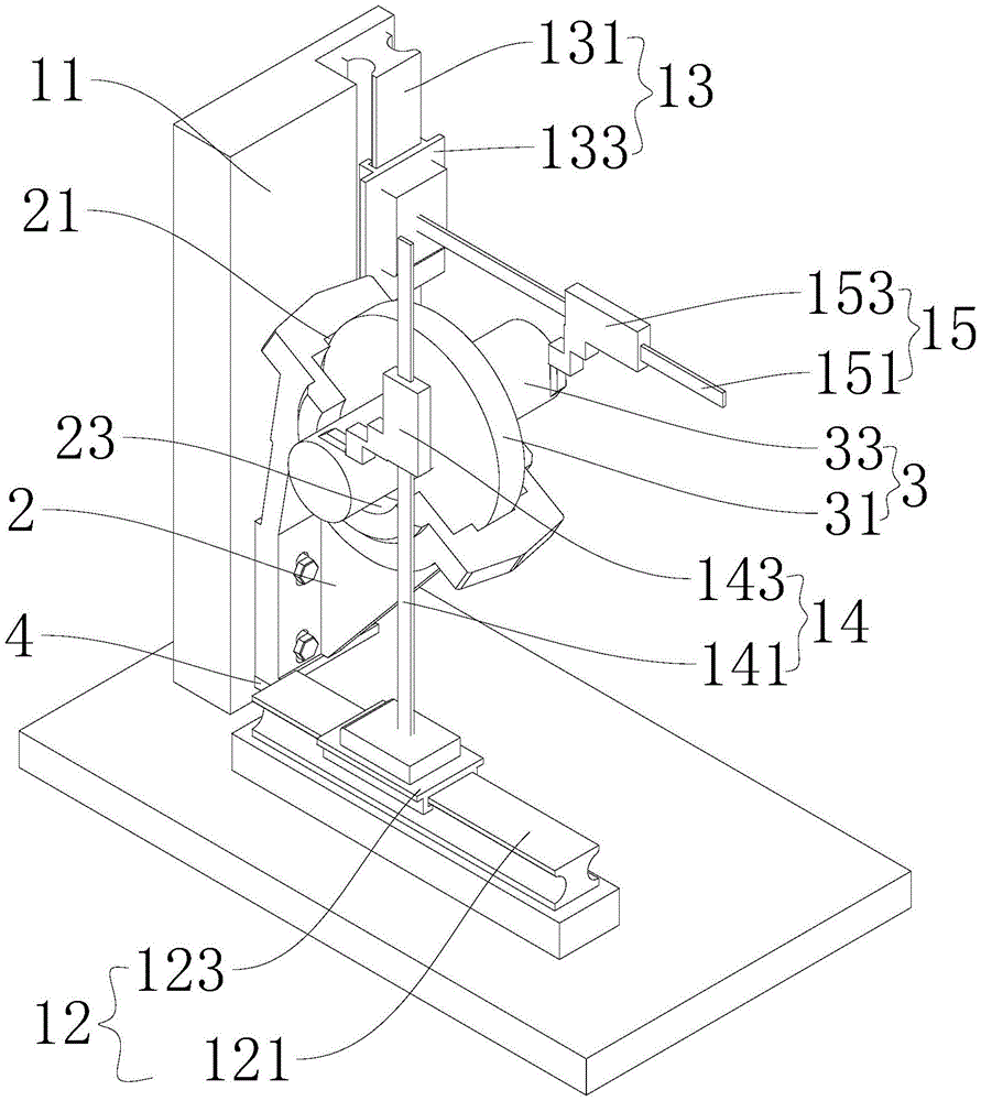
图1为本实用新型实施例一斜轴承座的尺寸测量装置的立体图;1 is a perspective view of a dimension measuring device for an inclined bearing seat according to an embodiment of the present invention;
图2为本实用新型实施例一斜轴承座的尺寸测量装置的工作示意图;Fig. 2 is the working schematic diagram of the dimension measuring device of the inclined bearing seat according to the embodiment of the present invention;
图3为本实用新型实施例一斜轴承座的立体图;FIG. 3 is a perspective view of an inclined bearing seat according to an embodiment of the present invention;
图4为本实用新型实施例一斜轴承座的另一视角立体图;4 is a perspective view of another perspective view of an inclined bearing seat according to an embodiment of the present invention;
图5为本实用新型实施例一斜轴承座的正视图;Fig. 5 is the front view of the inclined bearing seat according to the first embodiment of the present invention;
图6为本实用新型实施例一斜轴承座的尺寸测量装置的第一视角工作示意图;Fig. 6 is the working schematic diagram of the first angle of view of the dimension measuring device of the inclined bearing seat according to the embodiment of the present invention;
图7为本实用新型实施例一斜轴承座的尺寸测量装置的第二视角工作示意图。FIG. 7 is a working schematic diagram of a dimension measuring device for an inclined bearing seat from a second angle of view according to an embodiment of the present invention.
具体实施方式Detailed ways
为使本实用新型实施例的目的、技术方案和优点更加清楚,下面将结合本实用新型实施例,对本实用新型实施例中的技术方案进行清楚、完整地描述,显然,所描述的实施例是本实用新型一部分实施例,而不是全部的实施例。基于本实用新型中的实施例,本领域普通技术人员在没有作出创造性劳动前提下所获得的所有其他实施例,都属于本实用新型保护的范围。In order to make the purposes, technical solutions and advantages of the embodiments of the present utility model clearer, the technical solutions in the embodiments of the present utility model will be clearly and completely described below in conjunction with the embodiments of the present utility model. Obviously, the described embodiments are Some embodiments of the present invention, but not all embodiments. Based on the embodiments of the present invention, all other embodiments obtained by those of ordinary skill in the art without creative work fall within the protection scope of the present invention.
实施例一Example 1
如图1所示,本实施例提供一种斜轴承座的尺寸测量装置,包括测量机构1、限位机构3。As shown in FIG. 1 , the present embodiment provides a dimension measuring device of an inclined bearing seat, which includes a
如图1、图2所示,测量机构1包括基座11、第一滑动单元12、第二滑动单元13、第一测量单元、第二测量单元;基座11的竖截面为L形;基座11横板的顶端固定有第一滑动单元12,基座11竖板上靠近横板的一侧固定有第二滑动单元13,第一滑动单元12与第二滑动单元13之间设置有斜轴承座2,斜轴承座2固定于基座11的竖板上,斜轴承座2的下方设置有限位块4,限位块4固定于基座11的竖板上,起到限位的作用;第一滑动单元12包括相互配套进行水平滑动的第一滑轨121和第一滑块123,第一滑轨121固定于基座11的横板上,第一滑块123滑动连接于第一滑轨121上,第一滑块123的顶壁上固定有第一测量单元;第二滑动单元13包括相互配套进行垂直滑动的第二滑轨131和第二滑块133,第二滑轨131固定于基座11的竖板上,第二滑块133滑动连接于第二滑轨131上,第二滑块133的顶壁上固定有第二测量单元;第一测量单元为第一游标卡尺14,第二测量单元为第二游标卡尺15;第一游标卡尺14包括第一标尺141、第一量爪143,第一标尺141固定于第一滑块123的顶壁上,第一量爪143滑动设置于第一标尺141的尺身上,第一量爪143的底端与第一标尺141的尺身为垂直设置;第二游标卡尺15包括第二标尺151、第二量爪153,第二标尺151固定于第二滑块133的顶壁上,第二量爪153滑动设置于第二标尺151的尺身上,第二量爪153的底端与第二标尺151的尺身为垂直设置;第一量爪143、第二量爪153的底端均为可伸缩设置。As shown in Figures 1 and 2, the
如图3、图4、图5所示,斜轴承座2的竖截面类似于直角三角形,斜轴承座2的斜面通过螺栓固定于基座11的竖板上,斜轴承座2的短直角面顶端中部开设有第一安装口21,用于安装轴承,斜轴承座2的短直角面顶端前后侧处开设有第二安装口23,用于安装销轴,第一安装口21、第二安装口23均为半圆,第一安装口21的半径大于第二安装口23的半径。As shown in Figure 3, Figure 4, Figure 5, the vertical section of the
如图1、图2所示,限位机构3包括环规31、芯棒33;环规31为圆盘,环规31的中心处开设有安装孔,安装孔内固定有芯棒33,芯棒33为圆柱,芯棒33贯穿安装孔向两侧延伸;环规31的半径与轴承一致,芯棒33的半径与销轴一致,测量时,环规31设置于第一安装口21内,环规31两侧的芯棒33分别设置于两个第二安装口23内,第一量爪143的底端与后侧芯棒33的端面贴合,第二量爪153的底端与前侧芯棒33的端面贴合。As shown in Figures 1 and 2, the
装配时,如图5所示,需要测量中心高度L1、中心宽度L2的尺寸,需要分别建立第一基准(斜轴承座2底部的虚横线)、第二基准(斜轴承座2左侧的虚竖线);如图4、图6、图7所示,第一滑块123的上表面通过精确加工与第一基准面重合,第二滑块133的上表面通过精确加工与第二基准面重合;测量时,需要使用与第一安装口21尺寸(R1)相适配的环规31,与第二安装口23尺寸(R2)相适配的芯棒33,将芯棒33穿过环规31中心处开设的安装孔,然后将环规31安装在第一安装口21中,将芯棒33安装在第二安装口23中;芯棒33与环规31安装孔加工装备使用过渡配合,确保环规31外径安装面平稳贴合第一安装口21的安装面;然后通过螺栓将斜轴承座2安装于基座11的竖板上,装配时要注意将斜轴承座2的安装面完全贴合于基座11的竖板上,然后通过螺栓进行固定;During assembly, as shown in Figure 5, the dimensions of the center height L1 and the center width L2 need to be measured, and the first reference (the dotted horizontal line at the bottom of the inclined bearing seat 2) and the second reference (the left side of the inclined bearing seat 2) need to be established respectively. Dotted vertical line); as shown in Figure 4, Figure 6, Figure 7, the upper surface of the first sliding
L1尺寸的测量(图6所示):Measurement of L1 dimension (shown in Figure 6):
调整并移动第一量爪143,使第一量爪143底面与芯棒33的轴端面贴合,然后进行读数;所读出的数值=中心高度(L1)+芯棒半径(R2),中心高度(L1)=所读出的数值-芯棒半径(R2);Adjust and move the first measuring
L2尺寸的测量(图7所示):Measurement of L2 size (shown in Figure 7):
调整并移动第二量爪153,使第二量爪153底面与芯棒33的轴端面贴合,然后进行读数;所读出的数值=中心宽度(L2)+芯棒半径(R2),中心宽度(L2)=所读出的数值-芯棒半径(R2)。Adjust and move the
以上实施例仅用以说明本实用新型的技术方案,而非对其限制;尽管参照前述实施例对本实用新型进行了详细的说明,本领域的普通技术人员应当理解:其依然可以对前述各实施例所记载的技术方案进行修改,或者对其中部分技术特征进行等同替换;而这些修改或者替换,并不使相应技术方案的本质脱离本实用新型各实施例技术方案的精神和范围。The above embodiments are only used to illustrate the technical solutions of the present utility model, but not to limit them; although the present utility model has been described in detail with reference to the foregoing embodiments, those of ordinary skill in the art should understand that: it can still be used for the foregoing implementations. The technical solutions described in the examples are modified, or some technical features thereof are equivalently replaced; and these modifications or replacements do not make the essence of the corresponding technical solutions deviate from the spirit and scope of the technical solutions of the embodiments of the present invention.
Claims (10)
Priority Applications (1)
| Application Number | Priority Date | Filing Date | Title |
|---|---|---|---|
| CN202221139030.7U CN217303794U (en) | 2022-05-12 | 2022-05-12 | Size measuring device of inclined bearing seat |
Applications Claiming Priority (1)
| Application Number | Priority Date | Filing Date | Title |
|---|---|---|---|
| CN202221139030.7U CN217303794U (en) | 2022-05-12 | 2022-05-12 | Size measuring device of inclined bearing seat |
Publications (1)
| Publication Number | Publication Date |
|---|---|
| CN217303794U true CN217303794U (en) | 2022-08-26 |
Family
ID=82916815
Family Applications (1)
| Application Number | Title | Priority Date | Filing Date |
|---|---|---|---|
| CN202221139030.7U Active CN217303794U (en) | 2022-05-12 | 2022-05-12 | Size measuring device of inclined bearing seat |
Country Status (1)
| Country | Link |
|---|---|
| CN (1) | CN217303794U (en) |
Cited By (1)
| Publication number | Priority date | Publication date | Assignee | Title |
|---|---|---|---|---|
| CN114935293A (en) * | 2022-05-12 | 2022-08-23 | 蚌埠凯盛工程技术有限公司 | Dimensional measuring device for inclined bearing seat and measuring method thereof |
-
2022
- 2022-05-12 CN CN202221139030.7U patent/CN217303794U/en active Active
Cited By (1)
| Publication number | Priority date | Publication date | Assignee | Title |
|---|---|---|---|---|
| CN114935293A (en) * | 2022-05-12 | 2022-08-23 | 蚌埠凯盛工程技术有限公司 | Dimensional measuring device for inclined bearing seat and measuring method thereof |
Similar Documents
| Publication | Publication Date | Title |
|---|---|---|
| WO2018090353A1 (en) | Device for testing parallelism between workbench of bending machine and main shaft holes of frame | |
| CN110000639A (en) | A kind of roller diameter based on roll grinder and taper on-position measure device and measurement method | |
| CN210464320U (en) | Detection tool for shaft sleeve | |
| CN120926851A (en) | Gear short shaft measuring device and method | |
| WO2020238052A1 (en) | High-precision device for measuring excess length of optical fiber | |
| CN202329460U (en) | Taper hole measurement device | |
| CN211234344U (en) | Positioning device for three-coordinate automatic measurement of train axle size | |
| CN211317140U (en) | Deep hole step height measuring device | |
| CN204240901U (en) | Adjustable measurement measurer | |
| CN114935293B (en) | A dimension measuring device and measuring method for a slanted bearing housing | |
| CN103433808A (en) | Dial gage base scale display edge finder | |
| CN115647932B (en) | A method for controlling installation accuracy of detachable milling head | |
| CN109458914B (en) | Inclined hole depth measuring tool | |
| CN219403542U (en) | Y-direction hole detection device for milling machine screw nut seat | |
| CN103743328B (en) | Steering nut guide hole position degree detection apparatus | |
| CN218002408U (en) | Calibrating device for internal diameter dial indicator | |
| CN110174037A (en) | A kind of axis class processing detection device | |
| CN210718925U (en) | Fork truck portal internal opening measuring tool | |
| CN114322720A (en) | Tool for measuring symmetry degree of key groove of shaft part | |
| CN114414366B (en) | A double-station tensile specimen elongation measurement device | |
| CN109780964B (en) | Pulley wear detection device and detection method | |
| CN115930832A (en) | Device and method for measuring bending degree of a rod | |
| CN106767625A (en) | A kind of outside micrometer check and correction gauge rod calibrating installation and calibration method | |
| CN201133808Y (en) | Grating measuring apparatus | |
| CN223815059U (en) | A gap measuring component |
Legal Events
| Date | Code | Title | Description |
|---|---|---|---|
| GR01 | Patent grant | ||
| GR01 | Patent grant |