SUMMERY OF THE UTILITY MODEL
Not enough to prior art exists, the utility model aims at providing a teaching material printing machine's scraper structure convenient to installation has solved current printing comparatively loaded down with trivial details and can not change the problem of adjusting the extension of scraper with the scraper installation.
In order to achieve the above object, the utility model provides a following technical scheme: a scraper structure of a teaching material printing machine convenient to install comprises a frame body, wherein mounting plates are fixedly mounted at two ends of the frame body, a plurality of mounting bolts are sleeved in the mounting plates, backing rings are sleeved on the outer sides of the mounting bolts, mounting springs are fixedly mounted on one sides of the backing rings, sliding grooves are formed in two sides of the inner portion of the frame body, sliding blocks are movably mounted in the sliding grooves, scrapers are fixedly mounted on the opposite sides of the sliding blocks, two supporting blocks are fixedly mounted on two sides of each scraper, a half-ring sleeve is fixedly mounted at the tops of the two supporting blocks, an inner sleeve is movably sleeved on the inner side of the half-ring sleeve, a force stabilizing spring is fixedly mounted at the top of an inner cavity of the inner sleeve, a magnetic suction buckle is arranged at the bottom of the force stabilizing spring, four groups of mounting seats are arranged at the tops of the scrapers, and two supporting rods are fixedly mounted at the tops of the four groups of mounting seats, the outer sides of the two supporting rods are movably sleeved with first rings, the tops of the first rings are hinged with telescopic rods, the other ends of the telescopic rods are hinged with second rings, the inner sides of the second rings are sleeved with sliding rods, the inner threads of the frame body are connected with screw rods, and shaft seats are movably sleeved at the bottom ends of the screw rods.
Preferably, the mounting spring is sleeved outside the mounting bolt, and one end of the mounting bolt is provided with a cross groove.
Through adopting above-mentioned technical scheme, the advantage lies in the cross recess, and the convenient to use cross plays rotates the construction bolt.
Preferably, the bottom of the scraper is provided with a wear-resistant edge.
Through adopting above-mentioned technical scheme, the advantage lies in being convenient for cooperate the scraper to use, has increased holistic result of use.
Preferably, the ends of the two support blocks, which are far away from the scraper, are in sliding contact with the inside of the frame body.
Through adopting above-mentioned technical scheme, the advantage lies in being convenient for carry out stably with the position of scraper, deflection when having avoided the operation.
Preferably, one end of the inner sleeve, which is far away from the semi-ring sleeve, is fixedly installed at the top of the inner cavity of the frame body, the magnetic buckle is fixedly installed at the bottom of the inner cavity of the semi-ring sleeve, and the iron ring is fixedly installed at the bottom end of the force stabilizing spring.
Through adopting above-mentioned technical scheme, the advantage lies in avoiding the circumstances that steady power spring appears deflecting, has increased the effect of steady moment.
Preferably, the mounting seat is fixedly mounted at the top of the scraper through a bolt, and the bottom of the shaft seat is fixedly mounted at the top of the scraper.
By adopting the technical scheme, the scraper that the advantage lies in that the structure continues to cooperate next change uses, has increased the effect of being convenient for change and installation.
Preferably, the number of the slide bars is two, and the two slide bars are both fixedly mounted in the frame body.
Through adopting above-mentioned technical scheme, the advantage lies in that the slide bar provides the pulling force at top for second ring and telescopic link, is convenient for apply the effort, finds to promote the fastness.
Compared with the prior art, the beneficial effects of the utility model are that:
1. install the device in the position that the printing machine needs to use through the mounting panel, then in the installation through mounting bolt threaded connection in the hole that the printing machine was predetermineeing, then rotate extruded in-process at the mounting bolt inboard, one end compresses the backing ring to exert the effort in the inside of installation spring, make its opposite with the effort of installation spring, be convenient for in the printing machine use, avoided because its mechanical nature vibration and the drop that produces, the installation is more firm.
2. Through the scraper that sets up, articulated telescopic link is stretched between first ring and the second ring that branch and slide bar interdynamic cup jointed respectively when the scraper moves down, and first ring and second ring are applyed the pulling force at branch and slide bar under its flexible effort, be convenient for apply a pulling force between framework and the scraper, be convenient for stable, and the rampart of scraper both sides agrees with framework inner wall, it is stable to be convenient for cooperate between slider and the spout will do all can, the condition that moment deflected appears when having avoided striking off the operation, and the semi-ring cover cup joints the outside at the endotheca, cooperate inside steady force spring, it is stable with moment to be convenient for cooperate the screw rod, the volume that the scraper stretches out can be adjusted to this scheme, the unit mount is comparatively convenient, excellent in use effect.
Detailed Description
The technical solutions in the embodiments of the present invention will be described clearly and completely with reference to the accompanying drawings in the embodiments of the present invention, and it is to be understood that the described embodiments are only some embodiments of the present invention, not all embodiments. Based on the embodiments in the present invention, all other embodiments obtained by a person skilled in the art without creative work all belong to the protection scope of the present invention.
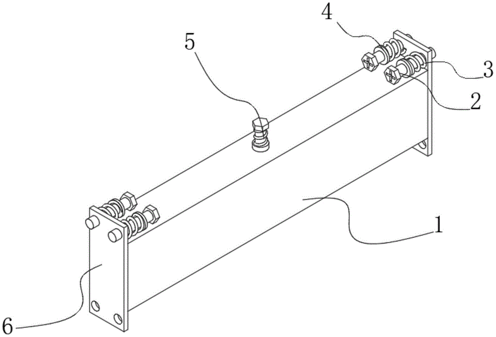
As shown in fig. 1-4, a scraper structure of a teaching material printing machine convenient for installation comprises a frame body 1, wherein both ends of the frame body 1 are fixedly provided with installation plates 6, the installation plates 6 are sleeved with a plurality of installation bolts 2, the outer sides of the installation bolts 2 are sleeved with backing rings 4, one side of the backing ring 4 is fixedly provided with an installation spring 3, both sides of the inside of the frame body 1 are provided with chutes 18, the inside of the chute 18 is movably provided with a slide block 12, the opposite side of the slide block 12 is fixedly provided with a scraper 7, both sides of the scraper 7 are fixedly provided with two support blocks 21, the tops of the two support blocks 21 are fixedly provided with a half ring sleeve 11, the inner side of the half ring sleeve 11 is movably sleeved with an inner sleeve 17, the top of the inner cavity of the inner sleeve 17 is fixedly provided with a force stabilizing spring 22, the bottom of the force stabilizing spring 22 is provided with a magnetic suction buckle 9, the tops of the scraper 7 are provided with four groups of installation seats 19, the tops of the four groups of installation seats 19 are fixedly provided with two support rods 16, the outer sides of the two supporting rods 16 are movably sleeved with a first ring 10, the top of the first ring 10 is hinged with a telescopic rod 14, the other end of the telescopic rod 14 is hinged with a second ring 13, the inner side of the second ring 13 is sleeved with a sliding rod 15, the inner thread of the frame body 1 is connected with a screw rod 5, and the bottom end of the screw rod 5 is movably sleeved with a shaft seat 8.
The working principle of the technical scheme is as follows:
during operation, an operator firstly installs the device at a position required by the printer through the mounting plate 6, then during the use process, the printer drives the whole position of the frame body 1 to be matched for operation, the frame body 1 is a cutter body, and if the position of the scraper 7 extending relative to the frame body 1 needs to be adjusted, the scraper is matched for operation of different printing rollers, firstly, the screw rod 5 is rotated, the screw rod 5 moves downwards under the action of the rotating force of the screw thread fit between the screw rod 5 and the frame body 1, the mode of the screw thread connection is similar to a bolt and a nut, the shaft seat 8 at the bottom of the screw rod 5 decomposes the rotating force and enables the scraper 7 to only receive the downward moving thrust of the screw rod 5, the scraper 7 keeps vertically and downwards sliding under the limit of the sliding blocks 12 and the sliding grooves 18 at two ends, and when the scraper 7 moves downwards, the telescopic rod 14 hinged between the first ring 10 and the second ring 13, which are respectively in interactive sleeved with the support rod 16 and the slide rod 15, is stretched, and the first ring 10 and the second ring 13 exert a pulling force on the supporting rod 16 and the sliding rod 15 under the action force of the extension and retraction thereof, so as to exert a pulling force between the frame body 1 and the scraper 7, so as to be convenient for stabilization, meanwhile, the telescopic rod 14 can be of a structure capable of fixing the extension and retraction position after the extension and retraction by electric or hydraulic extension, so as to be convenient for fixing the position so as to exert a pulling force on the scraper 7, then the supporting blocks 21 at the two sides of the scraper 7 are matched with the inner wall of the frame body 1, so as to be convenient for stabilizing the force between the sliding block 12 and the sliding groove 18, thereby avoiding the moment deflection during the scraping operation, the semi-ring sleeve 11 is sleeved at the outer side of the inner sleeve 17, and is matched with the internal force stabilizing spring 22, so as to exert an elastic force downwards on the supporting blocks 21 to be opposite to the pulling force exerted by the telescopic rod 14, so as to be convenient for stabilizing the moment by the screw rod 5, the action effect is similar to the installation spring 3, the extension amount of the scraper 7 can be adjusted, and the whole installation is convenient, the use effect is good.
In another embodiment, as shown in fig. 1-3, the mounting spring 3 is sleeved outside the mounting bolt 2, and one end of the mounting bolt 2 is provided with a cross-shaped groove.
Cross recess, convenient to use cross plays and rotates mounting bolt 2, in the hole that the installation was predetermine at the printing machine through mounting bolt 2 threaded connection, then rotate extruded in-process in mounting bolt 2 inboard, one end compresses backing ring 4, and apply the effort in the inside of installation spring 3, make it opposite with the effort of installation spring 3, be convenient for in the printing machine use, avoided because droing that its mechanical nature vibration produced, the installation is more firm.
In another embodiment, as shown in fig. 2-4, the bottom of the doctor blade 7 is provided with a wear-resistant edge 20.
The wear-resistant cutting edge 20 is positioned at the bottom end of the scraper 7, and the structure increases the wear resistance and toughness of the scraper under the processes of tempering after quenching and the like, is convenient to use by matching with the scraper 7 and increases the overall use effect.
In another embodiment, as shown in fig. 3 and 4, the ends of the two support blocks 21 remote from the scraper 7 are in sliding contact with the inside of the frame 1.
The support blocks 21 are fixed on two sides of the scraper 7, and the outer side of each support block is in extrusion contact with the inner wall of the frame body 1, so that the position of the scraper 7 is convenient to stabilize, and deflection during operation is avoided.
In another embodiment, as shown in fig. 2-4, one end of the inner sleeve 17 away from the semi-ring sleeve 11 is fixedly installed on the top of the inner cavity of the frame body 1, the magnetic catch 9 is fixedly installed on the bottom of the inner cavity of the semi-ring sleeve 11, and the bottom end of the force stabilizing spring 22 is fixedly installed with an iron ring.
This structure is convenient for make magnetism inhale when scraper 7 installation and detain 9 and steady power spring 22 inter attraction, is convenient for cooperate endotheca 17 and half ring cover 11 to carry out fixed position butt joint, avoids steady power spring 22 the condition that the deflection appears, has increased steady torque's effect.
In another embodiment, shown in fig. 2, the mounting seat 19 is fixedly mounted on the top of the scraper 7 by bolts, and the bottom of the shaft seat 8 is fixedly mounted on the top of the scraper 7.
The mounting seat 19 is mounted at the top of the scraper 7 through a bolt, the structure can enable the scraper 7 to be dismounted when needing to be replaced, the scraper 7, the half-ring sleeve 11, the support block 21 and the sliding block 12 are dismounted integrally, and other structures are continuously matched with the scraper 7 to be replaced next for use, so that the effect of convenience in replacement and mounting is increased.
In another embodiment, as shown in fig. 2, the number of the sliding rods 15 is two, and both the sliding rods 15 are fixedly installed inside the frame body 1.
The sliding rod 15 provides a top pulling force for the second ring 13 and the telescopic rod 14, so that an acting force is applied conveniently, and firmness is improved.
The utility model discloses a theory of operation and use flow: during operation, an operator firstly installs the device at a position required by the printer through the mounting plate 6, then the device is connected in a preset hole of the printer through the mounting bolt 2 in a threaded manner during the installation, then one end of the mounting bolt 2 compresses the backing ring 4 during the inward rotating extrusion process, and an acting force is applied to the inside of the mounting spring 3, so that the acting force is opposite to that of the mounting spring 3, the falling caused by mechanical vibration of the device is avoided during the use of the printer, the installation is firmer, then during the use process, the printer drives the whole position of the frame 1 to be matched, the frame 1 is integrally a cutter body, if the position of the scraper 7 extending relative to the frame 1 needs to be adjusted, and the scraper is matched with the operation of different printing rollers, firstly the screw rod 5 is rotated, and under the action of the rotating force of the screw thread matching between the screw rod 5 and the frame 1, the screw thread connection is similar to a bolt and a nut, a shaft seat 8 at the bottom of the screw rod 5 converts rotation torque and enables the scraper 7 to only receive downward moving thrust of the screw rod 5, the scraper 7 keeps vertically and downwardly sliding under the limit of a sliding block 12 and a sliding groove 18 at two ends, a telescopic rod 14 hinged between a first ring 10 and a second ring 13, which are in interaction sleeved connection with each other, of a support rod 16 and a sliding rod 15 is stretched when the scraper 7 moves downward, and the first ring 10 and the second ring 13 exert tension on the support rod 16 and the sliding rod 15 under the telescopic acting force of the first ring 10 and the second ring 13, so that the tension is conveniently exerted between the frame body 1 and the scraper 7, the stability is convenient, meanwhile, the telescopic rod 14 can be of a structure which can fix the telescopic position after being telescopic, the fixing position is convenient for exerting the tension on the scraper 7, then support blocks 21 at two sides of the scraper 7 are matched with the inner wall of the frame body 1, so that the force is conveniently stabilized between the sliding block 12 and the sliding groove 18, the condition that moment deflected appears when having avoided scraping the operation, and half ring cover 11 cup joints in the outside of endotheca 17, cooperates inside steady force spring 22, and it makes its opposite with the pulling force that telescopic link 14 was applyed at a piece 21 to apply elasticity downwards, and the cooperation screw rod 5 of being convenient for is stable with moment, and the effect is similar with installation spring 3, and the volume that scraper 7 stretched out can be adjusted to this scheme, and the integral erection is comparatively convenient, excellent in use effect.
Although embodiments of the present invention have been shown and described, it will be appreciated by those skilled in the art that changes, modifications, substitutions and alterations can be made in these embodiments without departing from the principles and spirit of the invention, the scope of which is defined in the appended claims and their equivalents.