CN217291329U - A milling machine with scrap recycling function for metal processing - Google Patents
A milling machine with scrap recycling function for metal processing Download PDFInfo
- Publication number
- CN217291329U CN217291329U CN202220803946.1U CN202220803946U CN217291329U CN 217291329 U CN217291329 U CN 217291329U CN 202220803946 U CN202220803946 U CN 202220803946U CN 217291329 U CN217291329 U CN 217291329U
- Authority
- CN
- China
- Prior art keywords
- sleeve
- seat
- milling machine
- driven
- mounting seat
- Prior art date
- Legal status (The legal status is an assumption and is not a legal conclusion. Google has not performed a legal analysis and makes no representation as to the accuracy of the status listed.)
- Expired - Fee Related
Links
- 239000002184 metal Substances 0.000 title claims abstract description 48
- 238000003801 milling Methods 0.000 title claims abstract description 28
- 238000004064 recycling Methods 0.000 title claims abstract description 16
- 238000010147 laser engraving Methods 0.000 claims description 12
- 239000002699 waste material Substances 0.000 claims description 7
- 230000000712 assembly Effects 0.000 claims description 3
- 238000000429 assembly Methods 0.000 claims description 3
- 238000000034 method Methods 0.000 description 4
- 238000010586 diagram Methods 0.000 description 3
- 238000004140 cleaning Methods 0.000 description 2
- 230000009286 beneficial effect Effects 0.000 description 1
- 238000005516 engineering process Methods 0.000 description 1
- 238000004519 manufacturing process Methods 0.000 description 1
- 238000011084 recovery Methods 0.000 description 1
Images


Classifications
-
- Y—GENERAL TAGGING OF NEW TECHNOLOGICAL DEVELOPMENTS; GENERAL TAGGING OF CROSS-SECTIONAL TECHNOLOGIES SPANNING OVER SEVERAL SECTIONS OF THE IPC; TECHNICAL SUBJECTS COVERED BY FORMER USPC CROSS-REFERENCE ART COLLECTIONS [XRACs] AND DIGESTS
- Y02—TECHNOLOGIES OR APPLICATIONS FOR MITIGATION OR ADAPTATION AGAINST CLIMATE CHANGE
- Y02P—CLIMATE CHANGE MITIGATION TECHNOLOGIES IN THE PRODUCTION OR PROCESSING OF GOODS
- Y02P70/00—Climate change mitigation technologies in the production process for final industrial or consumer products
- Y02P70/10—Greenhouse gas [GHG] capture, material saving, heat recovery or other energy efficient measures, e.g. motor control, characterised by manufacturing processes, e.g. for rolling metal or metal working
Landscapes
- Processing Of Solid Wastes (AREA)
Abstract
本实用新型涉及铣床技术领域,尤其涉及一种金属加工带有废料回收功能的铣床。其技术方案包括:加工箱、升降台和底座,安装座正面通过滑槽座安装有升降台,升降台顶部通过滑轨安装有调节座,升降台顶部安装有加工箱,安装座内部一侧安装有从动齿盘,从动齿盘顶部安装有螺纹杆,螺纹杆外侧安装有螺纹套。本实用新型通过伺服电机通电运行带动主动齿盘正反旋转,利用旋转的主动齿盘与从动齿盘齿合带动螺纹杆正反旋转,通过正反旋转的螺纹杆与螺纹套配合带动升降台进行垂直升降调节,增加了装置操作平台高度可调节的功能,从而便于根据使用者身高进行调节,方便不同身高的工作人员进行使用,提高了装置使用的便利性。
The utility model relates to the technical field of milling machines, in particular to a milling machine with a scrap recycling function for metal processing. Its technical scheme includes: a processing box, a lifting table and a base, a lifting table is installed on the front of the mounting seat through a chute seat, an adjusting seat is installed on the top of the lifting table through a sliding rail, a processing box is installed on the top of the lifting table, and the inner side of the mounting seat is installed There is a driven sprocket, a threaded rod is installed on the top of the driven sprocket, and a threaded sleeve is installed on the outside of the threaded rod. The utility model drives the positive and negative rotation of the driving gear plate through the power-on operation of the servo motor, the positive and negative rotation of the threaded rod is driven by the rotating driving gear plate and the driven gear plate, and the lifting platform is driven by the cooperation of the positive and negative rotating threaded rod and the threaded sleeve. The vertical lift adjustment adds the function of adjusting the height of the operating platform of the device, thereby facilitating adjustment according to the height of the user, facilitating the use of staff with different heights, and improving the convenience of using the device.
Description
技术领域technical field
本实用新型涉及铣床技术领域,具体为一种金属加工带有废料回收功能的铣床。The utility model relates to the technical field of milling machines, in particular to a milling machine with a scrap recycling function for metal processing.
背景技术Background technique
铣床主要指用铣刀对工件多种表面进行加工的机床,铣床除能铣削平面、沟槽、轮齿、螺纹和花键轴外,还能加工比较复杂的型面,效率较刨床高,在机械制造和修理部门得到广泛应用,在对金属加工时需要通过铣床进行加工,为此提出一种金属加工带有废料回收功能的铣床。Milling machines mainly refer to machine tools that use milling cutters to process various surfaces of workpieces. In addition to milling planes, grooves, gear teeth, threads and spline shafts, milling machines can also process more complex profiles, with higher efficiency than planers. It is widely used in mechanical manufacturing and repairing departments. When processing metal, it needs to be processed by a milling machine. Therefore, a milling machine with a scrap recycling function is proposed for metal processing.
经检索,专利公告号为CN215659254U公开带有金属回收机构的零部件加工用铣床,包括两个支撑板,两个支撑板的顶部设置有工作台,工作台的顶部后侧设置有铣床本体,工作台的顶部开设有凹槽,凹槽的底部开设有圆孔,工作台的底部设置有落料斗,落料斗的下方设置有与落料斗的出料口相对应的收集盒,工作台上设置有夹紧装置。After retrieval, the patent publication number CN215659254U discloses a milling machine for parts processing with a metal recovery mechanism, including two support plates, the tops of the two support plates are provided with a workbench, and the top rear side of the workbench is provided with a milling machine body. The top of the table is provided with a groove, the bottom of the groove is provided with a circular hole, the bottom of the worktable is provided with a blanking hopper, and a collection box corresponding to the discharge port of the blanking hopper is provided below the blanking hopper. Clamping device.
现有的铣床存在的缺陷是:The disadvantages of existing milling machines are:
1、现有的铣床操作平台高度都是固定的,无法根据使用者的身高进行高度调节,不方便不同身高的工作人员进行使用,不仅会影响工作人员的操作,还会影响装置使用的便利性,从而局限了装置的适用范围,降低了装置的实用性;1. The height of the existing milling machine operating platform is fixed, and the height cannot be adjusted according to the height of the user, which is inconvenient for staff with different heights to use, which will not only affect the operation of the staff, but also affect the convenience of the device. , thereby limiting the scope of application of the device and reducing the practicability of the device;
2、现有的铣床采用等距夹持的方法将金属件夹持在中心位置,从而局限了金属件的加工位置,无法根据金属件的加工需要进行调节夹持位置,不便于对金属件不同位置处进行加工,为此我们提出一种金属加工带有废料回收功能的铣床来解决现有的问题。2. The existing milling machine adopts the method of equidistant clamping to clamp the metal parts at the center position, thus limiting the processing position of the metal parts, and the clamping position cannot be adjusted according to the processing needs of the metal parts, which is inconvenient for different metal parts. For this reason, we propose a metal processing milling machine with scrap recycling function to solve the existing problem.
实用新型内容Utility model content
本实用新型的目的在于提供一种金属加工带有废料回收功能的铣床,以解决上述背景技术中提出的问题。The purpose of the present utility model is to provide a milling machine with scrap recycling function for metal processing, so as to solve the problems raised in the above background technology.
为实现上述目的,本实用新型提供如下技术方案:一种金属加工带有废料回收功能的铣床,包括加工箱、升降台和底座,所述底座顶部一侧安装有安装座,所述安装座顶部转动安装有旋转座,所述旋转座顶部安装有角度调节组件,所述安装座正面通过滑槽座安装有升降台,所述升降台顶部通过滑轨安装有调节座,所述升降台顶部安装有加工箱,所述加工箱内部两侧分别安装有夹持组件,所述夹持组件包括调节螺杆,所述调节螺杆外侧安装有螺套,所述螺套顶部安装有夹持架,所述安装座内部一侧安装有从动齿盘,所述从动齿盘顶部安装有螺纹杆,所述螺纹杆外侧安装有螺纹套,且螺纹套与升降台一侧连接。In order to achieve the above purpose, the present utility model provides the following technical solutions: a milling machine with scrap recycling function for metal processing, including a processing box, a lifting platform and a base, a mounting seat is installed on one side of the top of the base, and a top of the mounting seat is installed. A rotating seat is rotatably installed, an angle adjustment component is installed on the top of the rotating seat, a lifting platform is installed on the front of the mounting seat through a chute seat, an adjustment seat is installed on the top of the lifting platform through a sliding rail, and the top of the lifting platform is installed There is a processing box, and clamping components are installed on both sides of the inner side of the processing box. The clamping components include an adjustment screw, a screw sleeve is installed on the outside of the adjustment screw, and a clamping frame is installed on the top of the screw sleeve. A driven sprocket is installed on one side inside the mounting seat, a threaded rod is installed on the top of the driven sprocket, a threaded sleeve is installed on the outside of the threaded rod, and the threaded sleeve is connected to one side of the lifting platform.
通过伺服电机通电运行带动主动齿盘正反旋转,利用旋转的主动齿盘与从动齿盘齿合带动螺纹杆正反旋转,通过正反旋转的螺纹杆与螺纹套配合带动升降台进行垂直升降调节,增加了装置操作平台高度可调节的功能,从而便于根据使用者身高进行调节,方便不同身高的工作人员进行使用,提高了装置使用的便利性,调节螺杆的一端安装有转把,通过转把带动调节螺杆进行旋转,旋转的调节螺杆与螺套配合带动夹持架进行水平移动,从而便于根据金属件的加工需要进行调节夹持位置,从而方便对金属件不同位置处进行加工,同时也保证了金属件在加工时的稳定性,避免金属件在加工时发生晃动,提高了金属件加工的精密性,保证了金属件加工品质。The positive and negative rotation of the driving gear plate is driven by the power-on operation of the servo motor, and the positive and negative rotation of the threaded rod is driven by the rotating driving gear plate and the driven gear plate. Adjustment adds the function of adjusting the height of the operating platform of the device, so that it is convenient to adjust according to the height of the user, which is convenient for staff with different heights to use, and improves the convenience of using the device. Rotate the driving adjusting screw, and the rotating adjusting screw and the screw sleeve cooperate to drive the clamping frame to move horizontally, so as to facilitate the adjustment of the clamping position according to the processing needs of the metal parts, so as to facilitate the processing of different positions of the metal parts. It ensures the stability of metal parts during processing, avoids metal parts from shaking during processing, improves the precision of metal parts processing, and ensures the processing quality of metal parts.
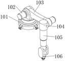
优选的,所述角度调节组件包括轴盘,轴盘的顶部一侧安装有伺服马达,伺服马达的输出端安装有轴臂,轴臂的一侧安装有角度轴套,角度轴套的内部安装有电动伸缩杆,电动伸缩杆的输出端安装有激光雕刻头。轴臂的一侧安装有伺服马达,且伺服马达的输出端与角度轴套连接,通过轴盘一侧的伺服马达通电运行带动轴臂进行仰卧角度旋转,同时通过轴臂一侧的伺服马达通电运行带动角度轴套进行旋转,通过角度轴套旋转带动电动伸缩杆进行旋转调节,从而便于调节激光雕刻头的角度,通过电动伸缩杆可便于根据金属件的厚度进行调节激光雕刻头与金属件的距离,便于将激光雕刻头调至合适位置,通过激光雕刻头通电运行可对金属件进行激光雕刻加工。Preferably, the angle adjustment assembly includes a shaft disc, a servo motor is installed on one side of the top of the shaft disc, a shaft arm is installed at the output end of the servo motor, an angle sleeve is installed on one side of the shaft arm, and the inside of the angle sleeve is installed There is an electric telescopic rod, and a laser engraving head is installed at the output end of the electric telescopic rod. A servo motor is installed on one side of the shaft arm, and the output end of the servo motor is connected with the angle bushing. The servo motor on the side of the shaft plate is powered on to drive the shaft arm to rotate at a supine angle, and at the same time, the servo motor on the side of the shaft arm is powered on. The operation drives the angle sleeve to rotate, and the rotation of the angle sleeve drives the electric telescopic rod to rotate and adjust, so as to facilitate the adjustment of the angle of the laser engraving head. The distance is convenient to adjust the laser engraving head to a suitable position, and the metal parts can be laser engraved through the power-on operation of the laser engraving head.
优选的,所述加工箱的内部活动安装有废料收集箱,且废料收集箱的正面安装有拉环。通过废料收集箱可对金属雕刻产生的废料进行收集,便于工作人员进行回收利用,并且通过拉环可抽拉出废料收集箱,便于对废料收集箱内部收集的废料进行清理。Preferably, a waste collection box is movably installed inside the processing box, and a pull ring is installed on the front of the waste collection box. The scrap generated by metal engraving can be collected through the scrap collection box, which is convenient for the staff to recycle, and the scrap collection box can be pulled out through the pull ring, which is convenient for cleaning the scrap collected inside the scrap collection box.
优选的,所述升降台的内部通过转盘安装有丝杆,丝杆的外侧安装有丝套,且丝套的顶部与调节座的底部连接。通过转把带动丝杆旋转,通过旋转的丝杆与丝套配合带动调节座进行纵向调节,通过调节座带动加工箱进行纵向调节。Preferably, a screw rod is installed inside the lifting platform through a turntable, a wire sleeve is installed on the outer side of the screw rod, and the top of the screw sleeve is connected with the bottom of the adjusting seat. The screw rod is driven to rotate by the turning handle, the adjusting seat is driven by the rotating screw rod and the screw sleeve for longitudinal adjustment, and the processing box is driven by the adjusting seat for longitudinal adjustment.
优选的,所述安装座内部的顶部安装有匀速电机,且匀速电机的输出端与旋转座的底部连接。通过匀速电机通电运行可带动旋转座进行匀速旋转,通过匀速旋转的旋转座可带动角度调节组件进行旋转调节加工位置,增加了装置的可调节性。Preferably, a constant speed motor is installed on the top inside the mounting seat, and the output end of the constant speed motor is connected to the bottom of the rotating seat. The rotating seat can be driven to rotate at a constant speed through the power-on operation of the constant speed motor, and the angle adjustment component can be driven to rotate and adjust the processing position through the rotating seat rotating at a constant speed, which increases the adjustability of the device.
优选的,所述安装座的内部一侧安装有伺服电机,伺服电机的输出端安装有主动齿盘,且主动齿盘一侧与从动齿盘齿合连接。通过伺服电机通电运行带动主动齿盘正反旋转,利用旋转的主动齿盘与从动齿盘齿合带动螺纹杆正反旋转。Preferably, a servo motor is installed on an inner side of the mounting seat, an output end of the servo motor is installed with a drive sprocket, and one side of the drive sprocket is geared and connected to the driven sprocket. The driving gear plate is driven to rotate forward and reverse by the power-on operation of the servo motor, and the threaded rod is driven to rotate forward and reverse by the engagement of the rotating driving gear plate and the driven gear plate.
与现有技术相比,本实用新型的有益效果是:Compared with the prior art, the beneficial effects of the present utility model are:
1、通过伺服电机通电运行带动主动齿盘正反旋转,利用旋转的主动齿盘与从动齿盘齿合带动螺纹杆正反旋转,通过正反旋转的螺纹杆与螺纹套配合带动升降台进行垂直升降调节,增加了装置操作平台高度可调节的功能,从而便于根据使用者身高进行调节,方便不同身高的工作人员进行使用,提高了装置使用的便利性。1. The driving gear plate is driven to rotate forward and reverse by the power-on operation of the servo motor. The rotating driving gear plate and the driven gear plate are engaged to drive the threaded rod to rotate forward and reverse. The vertical lift adjustment adds the function of adjusting the height of the operating platform of the device, which facilitates adjustment according to the height of the user, facilitates the use of staff with different heights, and improves the convenience of using the device.
2、通过转把带动调节螺杆进行旋转,旋转的调节螺杆与螺套配合带动夹持架进行水平移动,从而便于根据金属件的加工需要进行调节夹持位置,从而方便对金属件不同位置处进行加工,同时也保证了金属件在加工时的稳定性,避免金属件在加工时发生晃动,提高了金属件加工的精密性,保证了金属件加工品质。2. The adjusting screw is driven to rotate by the turning handle, and the rotating adjusting screw and the screw sleeve cooperate to drive the clamping frame to move horizontally, so that it is convenient to adjust the clamping position according to the processing needs of the metal parts, so as to facilitate the adjustment of different positions of the metal parts. At the same time, it also ensures the stability of metal parts during processing, avoids the shaking of metal parts during processing, improves the precision of metal parts processing, and ensures the processing quality of metal parts.
附图说明Description of drawings
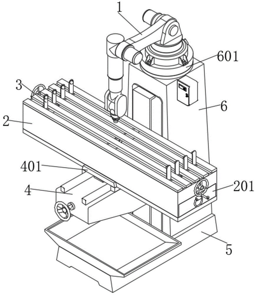
图1为本实用新型的主视图;Fig. 1 is the front view of the utility model;
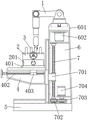
图2为本实用新型的剖面结构示意图;Fig. 2 is the sectional structure schematic diagram of the utility model;
图3为本实用新型的角度调节组件局部结构示意图;3 is a schematic diagram of the partial structure of the angle adjustment assembly of the present invention;
图4为本实用新型的夹持组件局部结构示意图。FIG. 4 is a schematic diagram of the partial structure of the clamping assembly of the present invention.
图中:1、角度调节组件;101、轴盘;102、伺服马达;103、轴臂;104、角度轴套;105、电动伸缩杆;106、激光雕刻头;2、加工箱;201、废料收集箱;3、夹持组件;301、调节螺杆;302、螺套;303、夹持架;4、升降台;401、调节座;402、丝杆;403、丝套;5、底座;6、安装座;601、旋转座;602、匀速电机;7、螺纹杆;701、螺纹套;702、从动齿盘;703、主动齿盘;704、伺服电机。In the figure: 1. Angle adjustment assembly; 101, axle disc; 102, servo motor; 103, axle arm; 104, angle bushing; 105, electric telescopic rod; 106, laser engraving head; 2, processing box; 201, scrap Collection box; 3, clamping assembly; 301, adjusting screw; 302, screw sleeve; 303, clamping frame; 4, lifting platform; 401, adjusting seat; 402, screw rod; 403, screw sleeve; 5, base; 6 , mounting seat; 601, rotating seat; 602, constant speed motor; 7, threaded rod; 701, threaded sleeve; 702, driven gear plate; 703, driving gear plate; 704, servo motor.
具体实施方式Detailed ways
下文结合附图和具体实施例对本实用新型的技术方案做进一步说明。The technical solutions of the present invention will be further described below with reference to the accompanying drawings and specific embodiments.
实施例一Example 1
如图1-4所示,本实用新型提出的一种金属加工带有废料回收功能的铣床,包括加工箱2、升降台4和底座5,底座5顶部一侧安装有安装座6,安装座6顶部转动安装有旋转座601,旋转座601顶部安装有角度调节组件1,安装座6正面通过滑槽座安装有升降台4,升降台4顶部通过滑轨安装有调节座401,升降台4顶部安装有加工箱2,加工箱2内部两侧分别安装有夹持组件3,夹持组件3包括调节螺杆301,调节螺杆301外侧安装有螺套302,螺套302顶部安装有夹持架303,安装座6内部一侧安装有从动齿盘702,从动齿盘702顶部安装有螺纹杆7,螺纹杆7外侧安装有螺纹套701,且螺纹套701与升降台4一侧连接。As shown in Figures 1-4, a milling machine with scrap recycling function for metal processing proposed by the present utility model includes a
基于实施例一的金属加工带有废料回收功能的铣床工作原理是:通过伺服电机704通电运行带动主动齿盘703正反旋转,利用旋转的主动齿盘703与从动齿盘702齿合带动螺纹杆7正反旋转,通过正反旋转的螺纹杆7与螺纹套701配合带动升降台4进行垂直升降调节,增加了装置操作平台高度可调节的功能,从而便于根据使用者身高进行调节,方便不同身高的工作人员进行使用,提高了装置使用的便利性,将金属件放置在加工箱2的顶部,通过转把带动调节螺杆301进行旋转,旋转的调节螺杆301与螺套302配合带动夹持架303进行水平移动,从而便于根据金属件的加工需要进行调节夹持位置,从而方便对金属件不同位置处进行加工,同时也保证了金属件在加工时的稳定性,避免金属件在加工时发生晃动,提高了金属件加工的精密性,保证了金属件加工品质,通过转把带动丝杆402旋转,通过旋转的丝杆402与丝套403配合带动调节座401进行纵向调节,通过调节座401带动加工箱2进行纵向调节,通过匀速电机602通电运行可带动旋转座601进行匀速旋转,通过匀速旋转的旋转座601可带动角度调节组件1进行旋转调节加工位置,增加了装置的可调节性,通过轴盘101一侧的伺服马达102通电运行带动轴臂103进行仰卧角度旋转,同时通过轴臂103一侧的伺服马达102通电运行带动角度轴套104进行旋转,通过角度轴套104旋转带动电动伸缩杆105进行旋转调节,从而便于调节激光雕刻头106的角度,通过电动伸缩杆105可便于根据金属件的厚度进行调节激光雕刻头106与金属件的距离,便于将激光雕刻头106调至合适位置,通过激光雕刻头106通电运行可对金属件进行激光雕刻加工,并且通过废料收集箱201可对金属雕刻产生的废料进行收集,便于工作人员进行回收利用。The working principle of the milling machine with scrap recycling function for metal processing based on the first embodiment is as follows: the
实施例二
如图2-4所示,本实用新型提出的一种金属加工带有废料回收功能的铣床,相较于实施例一,本实施例还包括:角度调节组件1包括轴盘101,轴盘101的顶部一侧安装有伺服马达102,伺服马达102的输出端安装有轴臂103,轴臂103的一侧安装有角度轴套104,角度轴套104的内部安装有电动伸缩杆105,电动伸缩杆105的输出端安装有激光雕刻头106,加工箱2的内部活动安装有废料收集箱201,且废料收集箱201的正面安装有拉环,升降台4的内部通过转盘安装有丝杆402,丝杆402的外侧安装有丝套403,且丝套403的顶部与调节座401的底部连接,安装座6内部的顶部安装有匀速电机602,且匀速电机602的输出端与旋转座601的底部连接,安装座6的内部一侧安装有伺服电机704,伺服电机704的输出端安装有主动齿盘703,且主动齿盘703一侧与从动齿盘702齿合连接。As shown in FIGS. 2-4 , the present invention proposes a milling machine for metal processing with a waste recycling function. Compared with the first embodiment, the present embodiment further includes: the angle adjustment assembly 1 includes a
本实施例中,通过废料收集箱201可对金属雕刻产生的废料进行收集,便于工作人员进行回收利用,并且通过拉环可抽拉出废料收集箱201,便于对废料收集箱201内部收集的废料进行清理,通过转把带动丝杆402旋转,通过旋转的丝杆402与丝套403配合带动调节座401进行纵向调节,通过调节座401带动加工箱2进行纵向调节,通过匀速电机602通电运行可带动旋转座601进行匀速旋转,通过匀速旋转的旋转座601可带动角度调节组件1进行旋转调节加工位置,增加了装置的可调节性,通过伺服电机704通电运行带动主动齿盘703正反旋转,利用旋转的主动齿盘703与从动齿盘702齿合带动螺纹杆7正反旋转。In this embodiment, the scraps generated by metal engraving can be collected through the
上述具体实施例仅仅是本实用新型的几种优选的实施例,基于本实用新型的技术方案和上述实施例的相关启示,本领域技术人员可以对上述具体实施例做出多种替代性的改进和组合。The above-mentioned specific embodiments are only several preferred embodiments of the present invention. Based on the technical solutions of the present invention and the relevant enlightenment of the above-mentioned embodiments, those skilled in the art can make various alternative improvements to the above-mentioned specific embodiments. and combination.
Claims (6)
Priority Applications (1)
| Application Number | Priority Date | Filing Date | Title |
|---|---|---|---|
| CN202220803946.1U CN217291329U (en) | 2022-04-08 | 2022-04-08 | A milling machine with scrap recycling function for metal processing |
Applications Claiming Priority (1)
| Application Number | Priority Date | Filing Date | Title |
|---|---|---|---|
| CN202220803946.1U CN217291329U (en) | 2022-04-08 | 2022-04-08 | A milling machine with scrap recycling function for metal processing |
Publications (1)
| Publication Number | Publication Date |
|---|---|
| CN217291329U true CN217291329U (en) | 2022-08-26 |
Family
ID=82938106
Family Applications (1)
| Application Number | Title | Priority Date | Filing Date |
|---|---|---|---|
| CN202220803946.1U Expired - Fee Related CN217291329U (en) | 2022-04-08 | 2022-04-08 | A milling machine with scrap recycling function for metal processing |
Country Status (1)
| Country | Link |
|---|---|
| CN (1) | CN217291329U (en) |
Cited By (1)
| Publication number | Priority date | Publication date | Assignee | Title |
|---|---|---|---|---|
| CN115488223A (en) * | 2022-11-09 | 2022-12-20 | 容德精机(江苏)机床有限公司 | Panel fixing device for lathe punches a hole |
-
2022
- 2022-04-08 CN CN202220803946.1U patent/CN217291329U/en not_active Expired - Fee Related
Cited By (1)
| Publication number | Priority date | Publication date | Assignee | Title |
|---|---|---|---|---|
| CN115488223A (en) * | 2022-11-09 | 2022-12-20 | 容德精机(江苏)机床有限公司 | Panel fixing device for lathe punches a hole |
Similar Documents
| Publication | Publication Date | Title |
|---|---|---|
| CN116460329A (en) | Radial drilling machine with novel improved structure | |
| CN218694025U (en) | Well-stable drilling tool for intermediate support | |
| CN218312665U (en) | Hardware fitting grinding device | |
| CN222288955U (en) | Aluminum pedal production cutting device | |
| CN217530276U (en) | Blank surface cleaning device for precision hardware machining | |
| CN218362331U (en) | Gantry milling table with two groups of clamping mechanisms and adjusting mechanism | |
| CN219310124U (en) | Radial drilling machine with drilling depth limiting mechanism | |
| CN2631672Y (en) | Multipurpose Horizontal Deep Hole Drilling Machine | |
| CN218800813U (en) | Lathe surface waste material clearance structure | |
| CN215509930U (en) | Numerical control drilling and milling machine for processing sectional materials | |
| CN113787215B (en) | Automatic drilling machine | |
| CN215880002U (en) | Automatic feeding and clamping equipment for bench drill | |
| CN210587340U (en) | Fixing device is used in milling machine processing convenient to adjust | |
| CN221966871U (en) | Adjustable milling cutter structure | |
| CN220295947U (en) | Rivet welding piece milling equipment | |
| CN220178236U (en) | Drilling machine with rotating function | |
| CN222404647U (en) | Grooving machine capable of collecting scraps | |
| CN222794607U (en) | Automatic blank feeding equipment for milling cutter processing | |
| CN222133766U (en) | Plasma body cutting blanking machine | |
| CN220806393U (en) | Vertical machining center auxiliary positioning frock | |
| CN221715807U (en) | A tapping mechanism with a replaceable tapping head | |
| CN223863407U (en) | Efficient cutting device for metal processing | |
| CN223848192U (en) | Door and window section bar cutting machine | |
| CN221159832U (en) | Nonferrous metal polishing device | |
| CN220881504U (en) | Reaming equipment for gear forging |
Legal Events
| Date | Code | Title | Description |
|---|---|---|---|
| GR01 | Patent grant | ||
| GR01 | Patent grant | ||
| CF01 | Termination of patent right due to non-payment of annual fee |
Granted publication date: 20220826 |
|
| CF01 | Termination of patent right due to non-payment of annual fee |