CN217276715U - A kind of air tightness detection device for boiler in thermal power plant - Google Patents
A kind of air tightness detection device for boiler in thermal power plant Download PDFInfo
- Publication number
- CN217276715U CN217276715U CN202220180006.1U CN202220180006U CN217276715U CN 217276715 U CN217276715 U CN 217276715U CN 202220180006 U CN202220180006 U CN 202220180006U CN 217276715 U CN217276715 U CN 217276715U
- Authority
- CN
- China
- Prior art keywords
- boiler
- closed box
- thermal power
- power plant
- support plate
- Prior art date
- Legal status (The legal status is an assumption and is not a legal conclusion. Google has not performed a legal analysis and makes no representation as to the accuracy of the status listed.)
- Withdrawn - After Issue
Links
- 238000001514 detection method Methods 0.000 title claims abstract description 19
- 238000007789 sealing Methods 0.000 claims abstract description 23
- XLYOFNOQVPJJNP-UHFFFAOYSA-N water Substances O XLYOFNOQVPJJNP-UHFFFAOYSA-N 0.000 claims description 10
- 239000011521 glass Substances 0.000 claims description 3
- 238000004891 communication Methods 0.000 abstract description 9
- 238000010586 diagram Methods 0.000 description 2
- 230000009286 beneficial effect Effects 0.000 description 1
- 238000013461 design Methods 0.000 description 1
- 238000000034 method Methods 0.000 description 1
- 238000012986 modification Methods 0.000 description 1
- 230000004048 modification Effects 0.000 description 1
- 238000012360 testing method Methods 0.000 description 1
- 238000012800 visualization Methods 0.000 description 1
Images


Landscapes
- Examining Or Testing Airtightness (AREA)
Abstract
本实用新型公开了一种用于热电厂锅炉的气密性检测装置,包括密闭箱体和透明容器,密闭箱体的前侧设有密封门,密闭箱体底部与透明容器之间通过连通管连接,连通管上设有单向阀;密闭箱体内部底部设有用于放置锅炉的支撑座,密闭箱体的上部设有支撑板,支撑板与升降装置连接,支撑板可在升降装置的带动下在密闭箱体内上下升降;支撑板上设有充气管,密闭箱体的顶部设有空气泵,空气泵连接有压力管,压力管贯穿密闭箱体的侧壁与所述充气管连接,充气管远离压力管的一端设有用于与锅炉连接充气接头。本实用新型通过升降装置带动支撑板进行升降,从而使支撑板上的充气接口能够随支撑板的移动而移动,使其能够适应不同高度规格的锅炉。

The utility model discloses an air tightness detection device for a thermal power plant boiler, which comprises a closed box body and a transparent container, a sealing door is arranged on the front side of the closed box body, and the bottom of the closed box body and the transparent container are connected by a communication pipe , There is a one-way valve on the communication pipe; the bottom of the closed box is provided with a support seat for placing the boiler, the upper part of the closed box is provided with a support plate, the support plate is connected with the lifting device, and the support plate can be driven by the lifting device. Lift up and down in the closed box; the support plate is provided with an inflatable pipe, the top of the closed box is provided with an air pump, the air pump is connected with a pressure pipe, and the pressure pipe runs through the side wall of the closed box and is connected to the inflatable pipe, and the inflatable pipe The end far away from the pressure pipe is provided with a charging joint for connecting with the boiler. The utility model drives the support plate to rise and fall through the lifting device, so that the air-filled interface on the support plate can move with the movement of the support plate, so that it can adapt to boilers of different height specifications.
Description
技术领域technical field
本实用新型涉及锅炉检测技术领域,尤其是涉及一种用于热电厂锅炉的气密性检测装置。The utility model relates to the technical field of boiler detection, in particular to an air tightness detection device for boilers in thermal power plants.
背景技术Background technique
在热电厂所使用的锅炉往往会用到气密性检测对锅炉的气密性进行检测,在热电厂锅炉的气密性检测过程中,现有的热电厂锅炉的气密性检测装置在使用时往往不能够实现对于不同高度规格的锅炉进行检测,不能够实现对于检测结果的可视化,不利于观测检测结果。Boilers used in thermal power plants often use air tightness detection to test the air tightness of boilers. It can realize the detection of boilers with different height specifications, but cannot realize the visualization of the detection results, which is not conducive to the observation of the detection results.
实用新型内容Utility model content
为解决上述技术问题,本实用新型目的在于提供一种用于热电厂锅炉的气密性检测装置。In order to solve the above-mentioned technical problems, the purpose of the present invention is to provide an air tightness detection device for a boiler of a thermal power plant.
根据本实用新型的一个目的,本实用新型提供一种用于热电厂锅炉的气密性检测装置,包括密闭箱体和透明容器,所述密闭箱体的前侧设有密封门,所述密闭箱体底部与透明容器之间通过连通管连接,所述连通管上设有单向阀;According to one object of the present utility model, the utility model provides an air tightness detection device for a boiler of a thermal power plant, which includes a closed box body and a transparent container, the front side of the closed box body is provided with a sealing door, and the closed box is provided with a sealing door. The bottom of the body and the transparent container are connected by a communication pipe, and the communication pipe is provided with a one-way valve;
所述密闭箱体内部底部设有用于放置锅炉的支撑座,所述密闭箱体的上部设有支撑板,所述支撑板与升降装置连接,所述支撑板可在所述升降装置的带动下在所述密闭箱体内上下升降;The inner bottom of the closed box is provided with a support seat for placing the boiler, the upper part of the closed box is provided with a support plate, the support plate is connected with the lifting device, and the support plate can be driven by the lifting device. Lift up and down in the airtight box;
所述支撑板上设有充气管,所述密闭箱体的顶部设有空气泵,所述空气泵连接有压力管,所述压力管贯穿所述密闭箱体的侧壁与所述充气管连接,所述充气管远离所述压力管的一端设有用于与所述锅炉连接充气接头。The support plate is provided with an inflatable pipe, the top of the airtight box is provided with an air pump, the air pump is connected with a pressure pipe, and the pressure pipe penetrates the side wall of the airtight case and is connected to the inflatable pipe , the end of the charging pipe away from the pressure pipe is provided with a charging joint for connecting with the boiler.
进一步地,所述密封门与所述密闭箱体铰接连接。Further, the airtight door is hingedly connected to the airtight box.
进一步地,所述密封门与所述密闭箱体之间设有密封条。Further, a sealing strip is provided between the sealing door and the sealing box.
进一步地,所述密封门前端面安装有轮盘把手,所述密封门内部安装有齿轮,所述齿轮环形侧面上下两侧啮合安装有锁杆。Further, a wheel handle is installed on the front end surface of the sealing door, a gear is installed inside the sealing door, and a lock rod is meshed and installed on the upper and lower sides of the annular side surface of the gear.
进一步地,所述升降装置包括伺服电机和螺杆,所述伺服电机固定在所述密闭箱体的内部顶端,所述螺杆的顶端与所述伺服电机的输出端连接,所述支撑板上开设有螺孔,所述螺杆贯穿所述螺孔与所述支撑板螺纹连接,所述密闭箱体相对的两个侧壁上开设有竖向导槽,所述支撑板的两侧设有限位块,所述限位块卡合在所述竖向导槽内且所述限位块能在所述竖向导槽内上下滑动。Further, the lifting device includes a servo motor and a screw rod, the servo motor is fixed on the inner top end of the airtight box, the top end of the screw rod is connected to the output end of the servo motor, and the support plate is provided with a A screw hole, the screw thread is connected to the support plate through the screw hole, vertical guide grooves are opened on the two opposite side walls of the airtight box, and limit blocks are arranged on both sides of the support plate, so The limit block is engaged in the vertical guide groove, and the limit block can slide up and down in the vertical guide groove.
进一步地,所述伺服电机的数量为两个,两个所述伺服电机的转速相同,每个所述伺服电机均连接有所述螺杆,所述螺杆均与所述支撑板螺纹连接。Further, the number of the servo motors is two, the rotational speed of the two servo motors is the same, each of the servo motors is connected with the screw rod, and the screw rod is all screwed with the support plate.
进一步地,所述透明容器为玻璃容器,所述透明容器内盛装有水。Further, the transparent container is a glass container, and the transparent container contains water.
进一步地,所述支撑板的两侧分别设有至少两块所述限位块。Further, at least two of the limiting blocks are respectively provided on both sides of the support plate.
进一步地,所述支撑座与所述密闭箱体底部之间设有缓冲层。Further, a buffer layer is provided between the support base and the bottom of the airtight box.
进一步地,所述缓冲层包括铺设于所述密闭箱体内的橡胶层。Further, the buffer layer includes a rubber layer laid in the airtight box.
有益效果:Beneficial effects:
本实用新型的技术方案通过升降装置带动支撑板进行升降,从而使支撑板上的充气接口能够随支撑板的移动而移动,使其能够适应不同高度规格的锅炉,使用时通过空气泵能够输出空气,通过充气管将空气输入到锅炉主体内部,当所检测锅炉的气密性不够时,空气将会从锅炉中渗出,进入密闭箱体内部,从而使得多出的空气会通过连通管进入透明容器内部,由于透明容器内部盛装有水,使得空气进入透明容器内部时,会在水中产生气泡,从而能够使人们很好的观测到锅炉是否具有气密性。The technical scheme of the utility model drives the support plate to lift through the lifting device, so that the air-filled interface on the support plate can move with the movement of the support plate, so that it can adapt to boilers of different heights and specifications, and the air pump can output air during use. , The air is input into the main body of the boiler through the inflatable pipe. When the air tightness of the detected boiler is not enough, the air will seep out from the boiler and enter the inside of the closed box, so that the excess air will enter the transparent container through the communication pipe. Inside, since the transparent container contains water, when the air enters the transparent container, air bubbles will be generated in the water, so that people can observe whether the boiler is airtight.
附图说明Description of drawings
为了更清楚地说明本实用新型具体实施方式或现有技术中的技术方案,下面将对具体实施方式或现有技术描述中所需要使用的附图作简单地介绍,显而易见地,下面描述中的附图是本实用新型的一些实施方式,对于本领域普通技术人员来讲,在不付出创造性劳动的前提下,还可以根据这些附图获得其他的附图。In order to more clearly illustrate the specific embodiments of the present invention or the technical solutions in the prior art, the following will briefly introduce the accompanying drawings that need to be used in the description of the specific embodiments or the prior art. Obviously, the following descriptions The accompanying drawings are some embodiments of the present invention. For those of ordinary skill in the art, other drawings can also be obtained based on these drawings without creative efforts.
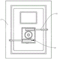
图1为本实用新型的结构示意图;Fig. 1 is the structural representation of the utility model;
图2为本实用新型的内部结构示意图;Fig. 2 is the internal structure schematic diagram of the utility model;
图3为本实用新型密封门的内部结构示意图;3 is a schematic diagram of the internal structure of the sealed door of the present invention;
附图标记说明:1、密闭箱体;2、透明容器;3、连通管;4、单向阀; 5、支撑座;6、缓冲层;7、锅炉;8、支撑板;9、伺服电机;10、螺杆; 11、竖向导槽;12、限位块;13、充气管;14、空气泵;15、压力管;16、充气接头;17、密封门;18、轮盘把手;19、齿轮;20、锁杆。Description of reference numerals: 1. Airtight box; 2. Transparent container; 3. Connecting pipe; 4. One-way valve; 5. Supporting seat; 6. Buffer layer; 7. Boiler; 8. Supporting plate; 9. Servo motor ;10, screw; 11, vertical guide channel; 12, limit block; 13, inflation pipe; 14, air pump; 15, pressure pipe; 16, inflation joint; 17, sealing door; 18, wheel handle; 19, Gear; 20. Lock lever.
具体实施方式Detailed ways
下面将结合实施例对本实用新型的技术方案进行清楚、完整地描述,显然,所描述的实施例是本实用新型一部分实施例,而不是全部的实施例。基于本实用新型中的实施例,本领域普通技术人员在没有做出创造性劳动前提下所获得的所有其他实施例,都属于本实用新型保护的范围。The technical solutions of the present invention will be clearly and completely described below with reference to the embodiments. Obviously, the described embodiments are a part of the embodiments of the present invention, but not all of the embodiments. Based on the embodiments of the present invention, all other embodiments obtained by those of ordinary skill in the art without creative work fall within the protection scope of the present invention.
在本实用新型的描述中,需要理解的是,术语"中心"、"纵向"、"横向 "、"长度"、"宽度"、"厚度"、"上"、"下"、"前"、"后"、"左"、"右"、" 竖直"、"水平"、"顶"、"底"、"内"、"外"、"顺时针"、"逆时针"等指示的方位或位置关系为基于附图所示的方位或位置关系,仅是为了便于描述本实用新型和简化描述,而不是指示或暗示所指的装置或元件必须具有特定的方位、以特定的方位构造和操作,因此不能理解为对本实用新型的限制。In the description of the present invention, it should be understood that the terms "center", "longitudinal", "lateral", "length", "width", "thickness", "upper", "lower", "front", "Back", "Left", "Right", "Vertical", "Horizontal", "Top", "Bottom", "Inner", "Outer", "Clockwise", "Counterclockwise" etc. Or the positional relationship is based on the orientation or positional relationship shown in the accompanying drawings, which is only for the convenience of describing the present invention and simplifying the description, rather than indicating or implying that the referred device or element must have a specific orientation, be constructed and operation, so it cannot be construed as a limitation to the present invention.
此外,术语"第一"、"第二"仅用于描述目的,而不能理解为指示或暗示相对重要性或者隐含指明所指示的技术特征的数量。由此,限定有"第一 "、"第二"的特征可以明示或者隐含地包括一个或者更多个所述特征。在本实用新型的描述中,"多个"的含义是两个或两个以上,除非另有明确具体的限定。此外,术语“安装”、“相连”、“连接”应做广义理解,例如,可以是固定连接,也可以是可拆卸连接,或一体地连接;可以是机械连接,也可以是电连接;可以是直接相连,也可以通过中间媒介间接相连,可以是两个元件内部的连通。对于本领域的普通技术人员而言,可以具体情况理解上述术语在本实用新型中的具体含义。In addition, the terms "first" and "second" are only used for descriptive purposes, and should not be understood as indicating or implying relative importance or implying the number of indicated technical features. Thus, features defined as "first", "second" may expressly or implicitly include one or more of said features. In the description of the present invention, "plurality" means two or more, unless otherwise expressly and specifically defined. In addition, the terms "installed", "connected" and "connected" should be understood in a broad sense, for example, it may be a fixed connection, a detachable connection, or an integral connection; it may be a mechanical connection or an electrical connection; it may be It is directly connected, or it can be indirectly connected through an intermediate medium, and it can be the internal connection of two components. For those of ordinary skill in the art, the specific meanings of the above terms in the present invention can be understood in specific situations.
实施例1Example 1
如图1-图3所示,As shown in Figure 1-3,
一种用于热电厂锅炉的气密性检测装置,包括密闭箱体1和透明容器2,透明容器2为玻璃容器,透明容器2内盛装有水。密闭箱体1底部与透明容器2之间通过连通管3连接,连通管3上设有单向阀4;在检测时,当所检测锅炉的气密性不够时,空气将会从锅炉中渗出,进入密闭箱体1内部,从而使得多出的空气通过连通管3进入透明容器2内部,由于透明容器2 内部设置有水,空气进入透明容器2内部时,会在水中产生气泡,从而能够使人们很好的观测到锅炉是否具有气密性。单向阀4可以防止水从透明容器2进入到密闭箱体1内。An air tightness detection device for a boiler of a thermal power plant, comprising a closed box 1 and a transparent container 2, the transparent container 2 is a glass container, and the transparent container 2 is filled with water. The bottom of the closed box 1 and the transparent container 2 are connected by a communication pipe 3, and a check valve 4 is arranged on the communication pipe 3; during detection, when the air tightness of the detected boiler is not enough, the air will seep out of the boiler , into the airtight box 1, so that the excess air enters the transparent container 2 through the communication pipe 3. Since the transparent container 2 is provided with water, when the air enters the transparent container 2, bubbles will be generated in the water, so that the It is well observed whether the boiler is airtight. The one-way valve 4 can prevent water from entering the closed box 1 from the transparent container 2 .
密闭箱体1内部底部设有用于放置锅炉的支撑座5,支撑座5与密闭箱体1底部之间设有缓冲层6,缓冲层6包括铺设于密闭箱体内1的橡胶层。通过支撑座5可以承载锅炉7,当通过起吊装置将锅炉7吊装入密闭箱体1 内时,缓冲层6可以为锅炉7提供缓冲。The inner bottom of the airtight box 1 is provided with a
密闭箱体1的上部设有支撑板8,支撑板8与升降装置连接,支撑板8 可在升降装置的带动下在密闭箱体1内上下升降;升降装置包括两个伺服电机9和螺杆10,两个伺服电机9的转速相同,每个伺服电机9均连接有螺杆10,伺服电机9固定在密闭箱体1的内部顶端,螺杆10的顶端与伺服电机9的输出端连接,支撑板8上开设有螺孔,螺杆10贯穿螺孔与支撑板8螺纹连接,密闭箱体1相对的两个侧壁上开设有竖向导槽11,支撑板8 的两侧设有两个限位块12,限位块12卡合在竖向导槽11内且限位块12能在竖向导槽11内上下滑动。The upper part of the airtight box body 1 is provided with a
支撑板8上设有充气管13,密闭箱体1的顶部设有空气泵14,空气泵 14连接有压力管15,压力管15贯穿密闭箱体1的侧壁与充气管13连接,充气管13远离压力管15的一端设有用于与锅炉7连接充气接头16。The
密闭箱体1的前侧设有密封门17,密封门17与密闭箱体1铰接连接,密封门1与密闭箱体17之间设有密封条,密封门17前端面安装有轮盘把手18,密封门1内部安装有齿轮19,齿轮19环形侧面上下两侧啮合安装有锁杆20,通过锁杆20可以将密封门17和密闭箱体1锁紧在一起,而且锁杆20采用常用的楔形设计,通过齿轮19的转动,可以使得楔形的锁杆 20将密封门17和密闭箱体1锁紧。The front side of the airtight box 1 is provided with a sealing
使用时,通过伺服电机9带动螺杆10转动,由于螺杆10与支撑板8 为螺纹连接,同时通过限位块12能够对支撑板8起到导向与限位作用,使得伺服电机转动能够带动支撑板8在螺杆10上升降,从而能够使得支撑板 8上的充气接头16能够随支撑板8的移动而移动,使其能够适应不同高度规格的锅炉。检测时,通过空气泵14输出空气,通过压力管15将压缩空气进入到充气管13,并通过充气接头16输入到锅炉7内部,当所检测锅炉 7的气密性不够时,空气将会从锅炉7中渗出,进入密闭箱体1内部,从而使得多出的空气会通过连通管3进入透明容器2内部,由于透明容器2内部设置有水,使得空气进入透明容器2内部时,会在水中产生气泡,从而能够使人们很好的观测到锅炉是否具有气密性。When in use, the
最后应说明的是:以上各实施例仅用以说明本实用新型的技术方案,而非对其限制;尽管参照前述各实施例对本实用新型进行了详细的说明,本领域的普通技术人员应当理解:其依然可以对前述各实施例所记载的技术方案进行修改,或者对其中部分或者全部技术特征进行等同替换;而这些修改或者替换,并不使相应技术方案的本质脱离本实用新型各实施例技术方案的范围。Finally, it should be noted that the above embodiments are only used to illustrate the technical solutions of the present utility model, but not to limit them; although the present utility model has been described in detail with reference to the foregoing embodiments, those of ordinary skill in the art should understand that : it can still modify the technical solutions recorded in the foregoing embodiments, or perform equivalent replacements to some or all of the technical features; and these modifications or replacements do not make the essence of the corresponding technical solutions deviate from the various embodiments of the present utility model Scope of technical solutions.
Claims (10)
Priority Applications (1)
| Application Number | Priority Date | Filing Date | Title |
|---|---|---|---|
| CN202220180006.1U CN217276715U (en) | 2022-01-21 | 2022-01-21 | A kind of air tightness detection device for boiler in thermal power plant |
Applications Claiming Priority (1)
| Application Number | Priority Date | Filing Date | Title |
|---|---|---|---|
| CN202220180006.1U CN217276715U (en) | 2022-01-21 | 2022-01-21 | A kind of air tightness detection device for boiler in thermal power plant |
Publications (1)
| Publication Number | Publication Date |
|---|---|
| CN217276715U true CN217276715U (en) | 2022-08-23 |
Family
ID=82903393
Family Applications (1)
| Application Number | Title | Priority Date | Filing Date |
|---|---|---|---|
| CN202220180006.1U Withdrawn - After Issue CN217276715U (en) | 2022-01-21 | 2022-01-21 | A kind of air tightness detection device for boiler in thermal power plant |
Country Status (1)
| Country | Link |
|---|---|
| CN (1) | CN217276715U (en) |
-
2022
- 2022-01-21 CN CN202220180006.1U patent/CN217276715U/en not_active Withdrawn - After Issue
Similar Documents
| Publication | Publication Date | Title |
|---|---|---|
| CN219608343U (en) | Valve detects leak protection device | |
| CN209979143U (en) | Airtightness testing device | |
| CN207456718U (en) | A kind of airtight detection platform of battery case | |
| CN210719529U (en) | Shock-proof pressure gauge detection tool | |
| CN217155735U (en) | Air tightness testing device for civil air defense anti-explosion floor drain | |
| CN208331765U (en) | A single-segment rubber-membrane-sealed gas tank | |
| CN221198816U (en) | Pressure testing device with perspective mirror | |
| CN220626047U (en) | Soft package battery packaging quality testing device | |
| CN217654685U (en) | Underwater sealing detection equipment for automobile manifold | |
| CN112268691B (en) | A self-weight balancing device used in the static loading side pull test of wind turbine blades | |
| CN110470437A (en) | A toilet pipeline leakage detection device and detection method | |
| CN218444357U (en) | Airtight visual detection device of air cleaner | |
| CN118111628A (en) | Rapid detection device and method for leakage of gearbox shell of heavy truck | |
| CN115524078A (en) | Oil conservator transformer and positive pressure sealing detection device thereof | |
| CN221404630U (en) | Air battery external packing material tightness detection device | |
| CN216132651U (en) | Load keeps valve seal detection device | |
| CN223611029U (en) | Chip package tightness test fixture | |
| CN219777023U (en) | A battery air tightness testing machine | |
| CN221464796U (en) | A natural gas pressure detection device | |
| CN216928886U (en) | Standing cavity device | |
| CN209296251U (en) | The airtight detection auxiliary connecting device of battery pack | |
| CN223841405U (en) | Intelligent pressure test leak detection equipment | |
| CN208818429U (en) | Press water air tightness tester | |
| CN224216260U (en) | Tightness detection device is used in ball valve production | |
| CN112881189A (en) | A transfer device for automotive engineering battery package check out test set |
Legal Events
| Date | Code | Title | Description |
|---|---|---|---|
| GR01 | Patent grant | ||
| GR01 | Patent grant | ||
| AV01 | Patent right actively abandoned | ||
| AV01 | Patent right actively abandoned | ||
| AV01 | Patent right actively abandoned |
Granted publication date: 20220823 Effective date of abandoning: 20250316 |
|
| AV01 | Patent right actively abandoned |
Granted publication date: 20220823 Effective date of abandoning: 20250316 |