CN217274405U - Steam condensate water cyclic utilization device for heat exchange station - Google Patents
Steam condensate water cyclic utilization device for heat exchange station Download PDFInfo
- Publication number
- CN217274405U CN217274405U CN202220627000.4U CN202220627000U CN217274405U CN 217274405 U CN217274405 U CN 217274405U CN 202220627000 U CN202220627000 U CN 202220627000U CN 217274405 U CN217274405 U CN 217274405U
- Authority
- CN
- China
- Prior art keywords
- water
- fixedly connected
- pipe
- drain pipe
- heat exchange
- Prior art date
- Legal status (The legal status is an assumption and is not a legal conclusion. Google has not performed a legal analysis and makes no representation as to the accuracy of the status listed.)
- Active
Links
- XLYOFNOQVPJJNP-UHFFFAOYSA-N water Substances O XLYOFNOQVPJJNP-UHFFFAOYSA-N 0.000 title claims abstract description 134
- 125000004122 cyclic group Chemical group 0.000 title abstract 2
- NBIIXXVUZAFLBC-UHFFFAOYSA-N Phosphoric acid Chemical compound OP(O)(O)=O NBIIXXVUZAFLBC-UHFFFAOYSA-N 0.000 claims abstract description 30
- 229910000147 aluminium phosphate Inorganic materials 0.000 claims abstract description 15
- 238000004064 recycling Methods 0.000 claims description 11
- 238000007789 sealing Methods 0.000 claims description 3
- 238000010438 heat treatment Methods 0.000 abstract description 4
- 238000009434 installation Methods 0.000 abstract description 4
- 239000002699 waste material Substances 0.000 abstract description 3
- 230000009286 beneficial effect Effects 0.000 abstract description 2
- 230000003020 moisturizing effect Effects 0.000 abstract 3
- 230000005494 condensation Effects 0.000 abstract 1
- 238000009833 condensation Methods 0.000 abstract 1
- 238000011084 recovery Methods 0.000 abstract 1
- 238000010586 diagram Methods 0.000 description 5
- 238000012986 modification Methods 0.000 description 2
- 230000004048 modification Effects 0.000 description 2
- 238000004891 communication Methods 0.000 description 1
- 238000005516 engineering process Methods 0.000 description 1
- 239000000945 filler Substances 0.000 description 1
- 230000003993 interaction Effects 0.000 description 1
- 238000000034 method Methods 0.000 description 1
Images


Classifications
-
- Y—GENERAL TAGGING OF NEW TECHNOLOGICAL DEVELOPMENTS; GENERAL TAGGING OF CROSS-SECTIONAL TECHNOLOGIES SPANNING OVER SEVERAL SECTIONS OF THE IPC; TECHNICAL SUBJECTS COVERED BY FORMER USPC CROSS-REFERENCE ART COLLECTIONS [XRACs] AND DIGESTS
- Y02—TECHNOLOGIES OR APPLICATIONS FOR MITIGATION OR ADAPTATION AGAINST CLIMATE CHANGE
- Y02P—CLIMATE CHANGE MITIGATION TECHNOLOGIES IN THE PRODUCTION OR PROCESSING OF GOODS
- Y02P80/00—Climate change mitigation technologies for sector-wide applications
- Y02P80/10—Efficient use of energy, e.g. using compressed air or pressurized fluid as energy carrier
Landscapes
- Heat-Exchange Devices With Radiators And Conduit Assemblies (AREA)
Abstract
Description
技术领域technical field
本实用新型涉及换热站技术领域,具体为一种换热站用蒸汽冷凝水循环利用装置。The utility model relates to the technical field of heat exchange stations, in particular to a steam condensed water recycling device for heat exchange stations.
背景技术Background technique
热力站是热力集中、交换的地方,按供热形式分直供站和间供站,前者是电厂直接供用户,温度高,控制难,浪费热能,是最初电厂余热福利供热的产物,间供站原理:电厂为一次线,小区为二次线,热源热网热用户连接处为热力站,设备有:板式换热器,循环泵,一二次线除污器,补水泵,水箱,计量表,控制阀门等。A thermal station is a place where heat is concentrated and exchanged. According to the form of heat supply, it is divided into direct supply station and indirect supply station. The former is directly supplied to users by the power plant. The temperature is high, it is difficult to control, and heat energy is wasted. Supply station principle: the power plant is the primary line, the residential area is the secondary line, and the heat source and heat network connection point is the thermal station. Meters, control valves, etc.
有些换热站在使用时,将站内的蒸汽冷凝水外排,浪费了水资源,无法很好的对水资源进行循环利用,对此有必要提出一种换热站用蒸汽冷凝水循环利用装置。When some heat exchange stations are in use, the steam condensate water in the station is drained out, which wastes water resources and cannot recycle water resources well. It is necessary to propose a steam condensate water recycling device for heat exchange stations.
实用新型内容Utility model content
本实用新型的目的在于提供一种换热站用蒸汽冷凝水循环利用装置,以解决上述背景技术中提出的问题。The purpose of the present invention is to provide a steam condensed water recycling device for a heat exchange station, so as to solve the problems raised in the above background technology.
为实现上述目的,本实用新型提供如下技术方案:一种换热站用蒸汽冷凝水循环利用装置,包括冷凝水收集槽与固定架,所述冷凝水收集槽的一端内壁固定连接有一根进气管,所述进气管贯穿延伸至冷凝水收集槽外,所述进气管延伸至冷凝水收集槽外的一端固定连接有一个蒸汽罐,且所述进气管贯穿延伸至蒸汽罐内,所述冷凝水收集槽远离进气管的一侧固定连接有一根第一排水管,所述第一排水管贯穿延伸至冷凝水收集槽外,所述冷凝水收集槽的一端设置有一个固定架,所述固定架的上表面固定连接有一个补水泵,且所述补水泵的输入端与第一排水管固定相连,所述冷凝水收集槽远离进气管的一侧固定连接有一根第二排水管,且所述第二排水管贯穿延伸至冷凝水收集槽外,所述固定架的上表面固定连接有一个吸水泵,所述吸水泵的输入端与第二排水管固定相连,所述补水泵的输出端固定连接有一个换热系统用补水管,所述吸水泵的输出端固定连接有一个磷酸车间循环水槽用补水管。In order to achieve the above purpose, the utility model provides the following technical solutions: a steam condensed water recycling device for a heat exchange station, comprising a condensed water collection tank and a fixing frame, and an air intake pipe is fixedly connected to the inner wall of one end of the condensed water collection tank, The air inlet pipe runs through and extends to the outside of the condensed water collection tank, and a steam tank is fixedly connected to one end of the air intake pipe that extends to the outside of the condensed water collection tank. A first drain pipe is fixedly connected to the side of the tank away from the air inlet pipe. The first drain pipe runs through and extends to the outside of the condensed water collection tank. One end of the condensed water collection tank is provided with a fixing frame. A make-up water pump is fixedly connected to the upper surface, and the input end of the make-up water pump is fixedly connected to the first drain pipe, a second drain pipe is fixedly connected to the side of the condensate collection tank away from the air inlet pipe, and the first drain pipe is fixedly connected. The second drain pipe runs through and extends to the outside of the condensed water collection tank, a suction pump is fixedly connected to the upper surface of the fixing frame, the input end of the suction pump is fixedly connected to the second drain pipe, and the output end of the make-up pump is fixedly connected There is a water supply pipe for the heat exchange system, and a water supply pipe for the circulating water tank of the phosphoric acid workshop is fixedly connected to the output end of the suction pump.
优选的,所述换热系统用补水管与磷酸车间循环水槽用补水管远离固定架的一端内壁均固定连接一个第一开关阀门,且所述第一开关阀门均贯穿延伸至换热系统用补水管与磷酸车间循环水槽用补水管外。Preferably, a first switch valve is fixedly connected to the inner wall of one end of the water supply pipe for the heat exchange system and the water supply pipe for the circulating water tank of the phosphoric acid workshop away from the fixing frame, and the first switch valve extends through the heat exchange system for water supply. Outside the pipe and the circulating water tank of the phosphoric acid workshop, the water supply pipe is used.
优选的,所述第一排水管位于冷凝水收集槽外的一端内壁固定相连有一个第二开关阀门,且所述第二开关阀门贯穿延伸至第一排水管外。Preferably, a second on-off valve is fixedly connected to the inner wall of one end of the first drain pipe located outside the condensed water collection tank, and the second on-off valve extends through the first drain pipe.
优选的,所述第二排水管位于冷凝水收集槽外的一端内壁固定相连有一个第三开关阀门,且所述第三开关阀门贯穿延伸至第二排水管外。Preferably, a third on-off valve is fixedly connected to the inner wall of one end of the second drain pipe outside the condensed water collection tank, and the third on-off valve extends through the second drain pipe.
优选的,所述冷凝水收集槽的上表面固定连接一个密封盖板。Preferably, a sealing cover plate is fixedly connected to the upper surface of the condensed water collection tank.
优选的,所述第一排水管与第二排水管均位于冷凝水收集槽下端。Preferably, both the first drain pipe and the second drain pipe are located at the lower end of the condensed water collection tank.
与现有技术相比,本实用新型的有益效果是:蒸汽罐将内部的蒸汽通过进气管传入冷凝水收集槽内,冷凝水收集槽内部的水蒸气冷凝形成水珠,当冷凝水收集槽内的水较多时,补水泵通过换热系统用补水管排入换热系统充当暖气循环水,吸水泵通过磷酸车间循环水槽用补水管将冷凝水移动进磷酸车间循环水槽内,供给换热设备,使多余的冷凝水回收再利用,实现节能减排,保护水资源浪费。Compared with the prior art, the beneficial effect of the present utility model is: the steam inside the steam tank is introduced into the condensed water collection tank through the air inlet pipe, and the water vapor in the condensed water collection tank is condensed to form water droplets. When there is a lot of water in the water, the make-up water pump is discharged into the heat-exchange system through the heat-exchange system and the make-up water pipe is used as the heating circulating water. , so that the excess condensate water can be recycled and reused to achieve energy saving and emission reduction, and protect the waste of water resources.
附图说明Description of drawings
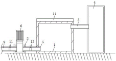
图1为本实用新型的正视结构示意图;Fig. 1 is the front view structure schematic diagram of the utility model;
图2为本实用新型的冷凝水收集槽俯视结构示意图;Fig. 2 is the top view structure schematic diagram of the condensed water collecting tank of the present invention;
图3为本实用新型的补水泵与吸水泵安装结构示意图;3 is a schematic diagram of the installation structure of the supplementary water pump and the suction water pump of the present invention;
图4为本实用新型的冷凝水收集槽正视结构示意图;Fig. 4 is the front structure schematic diagram of the condensed water collecting tank of the present invention;
图5为本实用新型的换热系统用补水管与磷酸车间循环水槽用补水管安装结构示意图。5 is a schematic diagram of the installation structure of the water supply pipe for the heat exchange system and the water supply pipe for the circulating water tank of the phosphoric acid workshop of the present invention.
图中:1、冷凝水收集槽;2、固定架;3、进气管;4、蒸汽罐;5、第一排水管;6、补水泵;7、第二排水管;8、吸水泵;9、换热系统用补水管;10、磷酸车间循环水槽用补水管;11、第一开关阀门;12、第二开关阀门;13、第三开关阀门;14、密封盖板。In the figure: 1. Condensate collection tank; 2. Fixing frame; 3. Intake pipe; 4. Steam tank; 5. First drain pipe; 6. Make-up pump; 7. Second drain pipe; 8. Suction pump; 9 1. Water supply pipe for heat exchange system; 10. Water supply pipe for circulating water tank in phosphoric acid workshop; 11. First switch valve; 12. Second switch valve; 13. Third switch valve; 14. Seal cover.
具体实施方式Detailed ways
下面将结合本实用新型实施例中的附图,对本实用新型实施例中的技术方案进行清楚、完整地描述,显然,所描述的实施例仅仅是本实用新型一部分实施例,而不是全部的实施例。基于本实用新型中的实施例,本领域普通技术人员在没有做出创造性劳动前提下所获得的所有其他实施例,都属于本实用新型保护的范围。The technical solutions in the embodiments of the present utility model will be clearly and completely described below with reference to the accompanying drawings in the embodiments of the present utility model. Obviously, the described embodiments are only a part of the embodiments of the present utility model, rather than all the implementations. example. Based on the embodiments of the present invention, all other embodiments obtained by those of ordinary skill in the art without creative work fall within the protection scope of the present invention.
请参阅图1-5,本实用新型提供一种技术方案:一种换热站用蒸汽冷凝水循环利用装置,包括冷凝水收集槽1与固定架2,冷凝水收集槽1的一端内壁固定连接有一根进气管3,进气管3贯穿延伸至冷凝水收集槽1外,进气管3延伸至冷凝水收集槽1外的一端固定连接有一个蒸汽罐4,且进气管3贯穿延伸至蒸汽罐4内,冷凝水收集槽1远离进气管3的一侧固定连接有一根第一排水管5,第一排水管5贯穿延伸至冷凝水收集槽1外,冷凝水收集槽1的一端设置有一个固定架2,固定架2的上表面固定连接有一个补水泵6,且补水泵6的输入端与第一排水管5固定相连,冷凝水收集槽1远离进气管3的一侧固定连接有一根第二排水管7,且第二排水管7贯穿延伸至冷凝水收集槽1外,固定架2的上表面固定连接有一个吸水泵8,吸水泵8的输入端与第二排水管7固定相连,补水泵6的输出端固定连接有一个换热系统用补水管9,吸水泵8的输出端固定连接有一个磷酸车间循环水槽用补水管10。Please refer to FIGS. 1-5, the present utility model provides a technical solution: a steam condensed water recycling device for a heat exchange station, comprising a condensed
其中,换热系统用补水管9与磷酸车间循环水槽用补水管10远离固定架2的一端内壁均固定连接一个第一开关阀门11,且第一开关阀门11均贯穿延伸至换热系统用补水管9与磷酸车间循环水槽用补水管10外。Among them, a first switch valve 11 is fixedly connected to the inner wall of one end of the
其中,第一排水管5位于冷凝水收集槽1外的一端内壁固定相连有一个第二开关阀门12,且第二开关阀门12贯穿延伸至第一排水管5外。A
其中,第二排水管7位于冷凝水收集槽1外的一端内壁固定相连有一个第三开关阀门13,且第三开关阀门13贯穿延伸至第二排水管7外。A
其中,冷凝水收集槽1的上表面固定连接一个密封盖板14。Wherein, a sealing
其中,第一排水管5与第二排水管7均位于冷凝水收集槽1下端。The
具体的,使用本实用新型时,蒸汽罐4将内部的蒸汽通过进气管3传入冷凝水收集槽1内,此时关闭第一排水管5与第二排水管7外的第二开关阀门12与第三开关阀门13,冷凝水收集槽1内部的水蒸气冷凝形成水珠,当冷凝水收集槽1内的水较多时,先开启第一排水管5外的第二开关阀门12,并开启固定架2上端的补水泵6,补水泵6通过连接的第一排水管5从冷凝水收集槽1内开始吸水,此时开启换热系统用补水管9外的第一开关阀门11,补水泵6将冷凝水通过换热系统用补水管9排入换热系统充当暖气循环水,为循环系统损失的水量充当填充剂,当冷凝水收集槽1内的冷凝水还有剩余时,关闭换热系统用补水管9外的第一开关阀门11与第一排水管5外的第二开关阀门12,开启第二排水管7外的第二开关阀门12,并开启吸水泵8,吸水泵8通过第二排水管7从冷凝水收集槽1内吸出冷凝水,并通过磷酸车间循环水槽用补水管10将冷凝水移动进磷酸车间循环水槽内,供给换热设备。Specifically, when the utility model is used, the steam inside the steam tank 4 is introduced into the condensed
在本实用新型的描述中,需要理解的是,术语“同轴”、“底部”、“一端”、“顶部”、“中部”、“另一端”、“上”、“一侧”、“顶部”、“内”、“前部”、“中央”、“两端”等指示的方位或位置关系为基于附图所示的方位或位置关系,仅是为了便于描述本实用新型和简化描述,而不是指示或暗示所指的装置或元件必须具有特定的方位、以特定的方位构造和操作,因此不能理解为对本实用新型的限制。In the description of the present invention, it should be understood that the terms "coaxial", "bottom", "one end", "top", "middle", "the other end", "upper", "one side", " The orientation or positional relationship indicated by "top", "inside", "front", "center", "both ends", etc. is based on the orientation or positional relationship shown in the accompanying drawings, and is only for the convenience of describing the present invention and simplifying the description , rather than indicating or implying that the referred device or element must have a specific orientation, be constructed and operated in a specific orientation, and therefore cannot be construed as a limitation on the present invention.
此外,术语“第一”、“第二”、“第三”、“第四”仅用于描述目的,而不能理解为指示或暗示相对重要性或者隐含指明所指示的技术特征的数量,由此,限定有“第一”、“第二”、“第三”、“第四”的特征可以明示或者隐含地包括至少一个该特征。In addition, the terms "first", "second", "third", "fourth" are only used for descriptive purposes and should not be understood as indicating or implying relative importance or implying the number of technical features indicated, Thus, features defined as "first", "second", "third", "fourth" may expressly or implicitly include at least one of such features.
在本实用新型中,除非另有明确的规定和限定,术语“安装”、“设置”、“连接”、“固定”、“旋接”等术语应做广义理解,例如,可以是固定连接,也可以是可拆卸连接,或成一体;可以是机械连接,也可以是电连接;可以是直接相连,也可以通过中间媒介间接相连,可以是两个元件内部的连通或两个元件的相互作用关系,除非另有明确的限定,对于本领域的普通技术人员而言,可以根据具体情况理解上述术语在本实用新型中的具体含义。In the present utility model, unless otherwise expressly specified and limited, terms such as "installation", "arrangement", "connection", "fixation", "swivel connection" should be understood in a broad sense, for example, it may be a fixed connection, It can also be detachable connection or integrated; it can be mechanical connection or electrical connection; it can be directly connected or indirectly connected through an intermediate medium, it can be the internal communication of two elements or the interaction of two elements Unless otherwise clearly defined, those of ordinary skill in the art can understand the specific meanings of the above terms in the present invention according to specific situations.
尽管已经示出和描述了本实用新型的实施例,对于本领域的普通技术人员而言,可以理解在不脱离本实用新型的原理和精神的情况下可以对这些实施例进行多种变化、修改、替换和变型,本实用新型的范围由所附权利要求及其等同物限定。Although the embodiments of the present invention have been shown and described, it will be understood by those skilled in the art that various changes and modifications can be made to these embodiments without departing from the principles and spirit of the present invention , alternatives and modifications, the scope of the present invention is defined by the appended claims and their equivalents.
Claims (6)
Priority Applications (1)
| Application Number | Priority Date | Filing Date | Title |
|---|---|---|---|
| CN202220627000.4U CN217274405U (en) | 2022-03-22 | 2022-03-22 | Steam condensate water cyclic utilization device for heat exchange station |
Applications Claiming Priority (1)
| Application Number | Priority Date | Filing Date | Title |
|---|---|---|---|
| CN202220627000.4U CN217274405U (en) | 2022-03-22 | 2022-03-22 | Steam condensate water cyclic utilization device for heat exchange station |
Publications (1)
| Publication Number | Publication Date |
|---|---|
| CN217274405U true CN217274405U (en) | 2022-08-23 |
Family
ID=82870613
Family Applications (1)
| Application Number | Title | Priority Date | Filing Date |
|---|---|---|---|
| CN202220627000.4U Active CN217274405U (en) | 2022-03-22 | 2022-03-22 | Steam condensate water cyclic utilization device for heat exchange station |
Country Status (1)
| Country | Link |
|---|---|
| CN (1) | CN217274405U (en) |
-
2022
- 2022-03-22 CN CN202220627000.4U patent/CN217274405U/en active Active
Similar Documents
| Publication | Publication Date | Title |
|---|---|---|
| CN103527267B (en) | Direct air-cooling unit system with plate-type evaporative condenser unit adopted | |
| CN103604310B (en) | Device for recovering and storing intermittent steam | |
| CN204646384U (en) | Diesel engine coolant and flue gas heat energy utilization device | |
| CN208139911U (en) | The cold and hot company of circulation and stress cold equipment waste heat is for device | |
| CN206071788U (en) | A kind of cooling tower backwater TRT | |
| CN221649244U (en) | High temperature water condensate recovery device | |
| CN204716318U (en) | One is driven induced draught fan small steam turbine exhaust steam residual heat integrative based on vapour and is utilized energy conserving system | |
| CN217684936U (en) | Cooling water waste heat recovery system | |
| CN206362206U (en) | Thermal power plant's Direct Air-Cooled spike cooling and residual neat recovering system | |
| CN101915437A (en) | Hydro-thermal recovery system in shower | |
| CN206488677U (en) | Aluminium cell low temperature exhaust heat recycling system | |
| CN212778764U (en) | Single-air-duct heat pipe heat recovery device | |
| CN203464786U (en) | Composite closed cooling tower | |
| CN203464800U (en) | Blowing-type cooling system | |
| CN206222827U (en) | a drying room | |
| CN222460406U (en) | Waste steam and waste heat recovery device of sludge drying machine | |
| CN209164039U (en) | A summer back pressure reduction and exhaust steam waste heat recovery device for air-cooled units | |
| CN207702551U (en) | A kind of residual heat using device | |
| CN221279691U (en) | A geothermal resource collection and storage device | |
| CN205119860U (en) | Intelligence temperature control technology improves condenser vacuum energy saving optimization device | |
| CN220524735U (en) | Water tank and heat exchange equipment | |
| CN218821884U (en) | Small-size mechanical cooling tower evaporation steam extraction recovery unit | |
| CN210036324U (en) | High-efficient vacuum system of cogeneration | |
| CN217109721U (en) | Condensed water backwater device of small-sized heating heat exchange unit | |
| CN223663541U (en) | A waste heat utilization device for ground source heat pumps |
Legal Events
| Date | Code | Title | Description |
|---|---|---|---|
| GR01 | Patent grant | ||
| GR01 | Patent grant |