Composite complete machine structure of offshore wind power cylinder type foundation and mixed tower
Technical Field
The utility model relates to a wind power generation technical field, concretely relates to marine wind power section of thick bamboo type basis and compound complete machine structure of mixing tower.
Background
The offshore wind power composite cylinder type foundation is an offshore wind turbine foundation structure which enables a cylinder body to be inserted into a seabed through internal and external pressure difference formed by pumping water and gas in a cylinder, consists of a prestressed arc-shaped reinforced concrete structure and a wide and shallow steel cylinder body, and has the characteristics of great self weight and shallow buried. The steel cylinder body at the lower part of the composite cylinder type foundation is inserted into the seabed soil body to provide bearing capacity; the upper prestressed arc-shaped reinforced concrete structure is partially immersed in water to bear the long-term marine environment effects of ocean currents, waves, growth of marine organisms and the like; the top of the prestressed arc reinforced concrete structure is connected with a fan tower cylinder through a high-strength bolt. As a novel fan foundation structure, the composite cylindrical foundation can be integrally installed on the sea as compared with a traditional pile foundation, and the foundation construction, the fan hoisting, the complete machine debugging and the like are all completed on the land, so that the standardized and modularized manufacturing of the fan foundation and the upper fan is realized, the manufacturing cost is reduced, the construction period is shortened, and the composite cylindrical foundation has remarkable advantages and wide application prospect.
The composite cylindrical foundation is manufactured on land, the combined structure of the composite cylindrical foundation and the fan bottom section tower drum is hoisted into a harbor basin through a gantry crane, then the combined structure is bound to a fan installation ship, and then the rest fan tower drum and the engine room are hoisted. After the fan and the foundation are assembled, the wind power plant is transported to a wind power plant through a fan installation ship, ship positioning and complete machine (the fan and the foundation) sinking installation are carried out, and therefore a complete power generation single project is completed.
At present, the tower barrels adopted by the domestic offshore wind turbine are all steel structures, and along with the capacity maximization of an offshore wind turbine set, the tower barrels still adopting all-steel structures lead to higher and higher construction cost, are connected by flanges and bolts between the tower barrels and are in point connection, and the overall stability is poor.
SUMMERY OF THE UTILITY MODEL
To the defect among the prior art, the utility model provides a pair of marine wind power section of thick bamboo type basis and compound complete machine structure of mixing the tower has solved the tower section of thick bamboo that marine fan adopted and has been the steel construction, and the cost is high, and adopts the point type to connect between a tower section of thick bamboo, the poor technical problem of overall stability.
In order to achieve the above purpose, the utility model discloses a following technical scheme realizes:
a composite complete machine structure of an offshore wind power cylinder type foundation and a hybrid tower comprises a composite cylinder type foundation, a steel-concrete tower cylinder, a wind turbine generator and steel strands; the composite cylinder type foundation comprises a steel cylinder body penetrating into a seabed, a concrete bottom plate and a concrete arc transition section, wherein the concrete bottom plate and the concrete arc transition section are integrally arranged, and the concrete bottom plate is arranged on the top surface of the steel cylinder body; the reinforced concrete tower barrel comprises a concrete tower barrel section and a steel structure tower barrel section which are sequentially connected, wherein the number of the concrete tower barrel sections is at least two, the bottom surface of the concrete tower barrel section positioned at the lowest position is abutted against the top surface of the concrete arc transition section, the top surface of the concrete tower barrel section positioned at the uppermost position is connected with the bottom surface of the steel structure tower barrel section through a connecting component, and the wind turbine generator is arranged on the top surface of the steel structure tower barrel section; the connecting assembly comprises an anchor plate arranged on the top surface of the uppermost concrete tower cylinder section, a T-shaped flange arranged on the periphery of the bottom of the steel structure tower cylinder section and a bolt connected between the anchor plate and the T-shaped flange; one end of the steel strand is anchored on the top surface of the anchor plate, and the other end of the steel strand penetrates through the two concrete tower barrel sections and the concrete arc transition section in sequence and then is anchored with the concrete bottom plate; the steel strands are arranged uniformly around the circumference of the concrete tower barrel section.
Optionally, the concrete bottom plate, the concrete arc transition section and the concrete tower barrel section are all prefabricated members, and a hole for a steel strand to pass through is reserved in each of the concrete arc transition section and the concrete tower barrel section.
Optionally, an annular groove is formed in the periphery of the joint of the concrete bottom plate and the concrete arc transition section, the steel strand penetrates through the concrete arc transition section and then is anchored with the wall of the annular groove, and the annular groove is filled with anchor sealing concrete.
Optionally, a base plate is arranged on the top surface of the concrete bottom plate, an anchor rod is embedded in the concrete bottom plate, and the anchor rod penetrates through the base plate and is fixedly connected with the base plate through a nut; the backing plate has a plurality ofly and with steel strand wires one-to-one, the backing plate top surface is equipped with the anchor subassembly, the steel strand wires pass through the anchor subassembly and concrete bottom plate anchor.
Optionally, the anchor rod is arranged obliquely, and the extension direction of the anchor rod is axially coplanar with the concrete arc transition section.
Optionally, the anchor rod and the concrete arc transition section form an included angle of 30-60 degrees in the axial direction.
Optionally, each backing plate is connected with two anchor rods, and the two anchor rods are respectively arranged on two sides of the anchoring assembly.
Optionally, a grouting material is filled between the anchor plate and the T-shaped flange.
According to the above technical scheme, the beneficial effects of the utility model are that:
1) the offshore wind turbine tower cylinder with at least 2/3 heights is replaced by a prestressed concrete structure from a steel structure, so that flanges for connecting segmented tower cylinders can be reduced, the steel consumption of the structure is reduced, and the construction cost of the tower cylinder can be reduced;
2) the concrete tower barrel section and the concrete arc transition section are connected in series through the steel strand and then tensioned, all the prefabricated parts are integrally connected, and then the top steel structure tower barrel section and the steel strand are tensioned through the connecting assembly, so that the integral stability of the fan tower barrel is improved;
3) the rigidity of the mixed tower structure is higher than that of a steel structure tower cylinder, so that the rigidity of the whole structure can be increased, the load of a fan is reduced, and the construction cost of the whole structure is further reduced;
4) the weight of the mixed tower structure is far larger than that of a steel structure tower barrel, and the anti-overturning bearing capacity of the whole structure is improved due to the increase of the weight of the whole structure.
Drawings
In order to more clearly illustrate the embodiments of the present invention or the technical solutions in the prior art, the drawings used in the embodiments or the technical solutions in the prior art will be briefly described below. Throughout the drawings, like elements or portions are generally identified by like reference numerals. In the drawings, elements or portions are not necessarily drawn to scale.
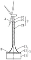
FIG. 1 is a schematic structural diagram of a composite complete machine of an offshore wind power cylinder type foundation and a mixing tower;
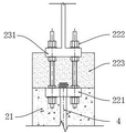
FIG. 2 is an enlarged view of the connection assembly at A of FIG. 1;
FIG. 3 is an enlarged view at B of FIG. 1;
FIG. 4 is a schematic perspective view of a composite cylindrical foundation;
FIG. 5 is an enlarged view at C of FIG. 4;
FIG. 6 is a cross-sectional view of a composite barrel foundation;
FIG. 7 is a schematic view of pre-embedded anchor rods in a concrete slab;
reference numerals:
1-a composite cylindrical foundation, 2-a steel-concrete tower, 3-a wind turbine generator and 4-a steel strand;
11-steel cylinder body, 12-concrete bottom plate, 13-concrete arc transition section, 21-concrete tower cylinder section, 22-connecting assembly, 23-steel structure tower cylinder section, 41-backing plate and 42-anchor rod;
221-anchor plate, 222-bolt, 223-grouting material and 231-T type flange.
Detailed Description
Embodiments of the present invention will be described in detail below with reference to the accompanying drawings. The following examples are only used to illustrate the technical solutions of the present invention more clearly, and therefore are only used as examples, and the protection scope of the present invention is not limited thereby.
Referring to fig. 1-7, the utility model provides a compound complete machine structure of marine wind power cylindrical foundation and mixed tower, including compound cylindrical foundation 1, steel-concrete tower section of thick bamboo 2, wind turbine generator system 3 and steel strand wires 4. The composite cylinder type foundation 1 comprises a steel cylinder body 11 penetrating into a seabed, a concrete bottom plate 12 and a concrete arc transition section 13, wherein the concrete bottom plate 12 and the concrete arc transition section 13 are integrally arranged, the concrete bottom plate 12 is arranged on the top surface of the steel cylinder body 11, and the diameter of the steel cylinder body 11 is generally 30-40 m. The steel-concrete tower barrel 2 comprises a concrete tower barrel section 21 and a steel structure tower barrel section 23 which are sequentially connected, and an offshore wind turbine tower barrel generally comprises three tower barrels, so that the engineering cost is reduced, the anti-overturning bearing capacity of the whole structure is increased, two tower barrel sections are replaced by the concrete tower barrel section 21, the bottom surface of the concrete tower barrel section 21 located at the bottom is abutted to the top surface of the concrete arc transition section 13, the top surface of the concrete tower barrel section 21 located at the top is connected with the bottom surface of the steel structure tower barrel section 23 through a connecting assembly 22, and the wind turbine generator 3 is arranged on the top surface of the steel structure tower barrel section 23. The concrete bottom plate 12, the concrete arc transition section 13 and the concrete tower barrel section 21 are all prefabricated members.
Specifically, referring to fig. 2, the connection assembly 22 includes an anchor plate 221 disposed on the top surface of the uppermost concrete tower tube section 21, a T-shaped flange 231 disposed on the outer periphery of the bottom of the steel structure tower tube section 23, and a bolt 222 connected between the anchor plate 221 and the T-shaped flange 231; 4 one ends of steel strand wires anchor at anchor slab 221 top surface to through 4 tensioning loads of anchor slab 221 dispersion steel strand wires, concrete arc changeover portion 13 and concrete tower section of thick bamboo section 21's inside all reserves the hole that supplies steel strand wires 4 to walk, 4 other ends of steel strand wires run through in proper order behind the hole that two concrete tower section of thick bamboo sections 21 and concrete arc changeover portion 13 predetermine with concrete bottom plate 12 anchors, stretch-draw behind establishing ties concrete tower section of thick bamboo section 21 and concrete arc changeover portion 13 promptly, make each prefabricated component integral connection. The number of the steel strands 4 is multiple, the steel strands 4 are uniformly distributed around the circumference of the concrete tower barrel section 21, and the number of the steel strands 4 is generally 48-60. Preferably, the gap between the anchor plate 221 and the T-flange 231 is filled with a high-strength grout 223.
In an embodiment, referring to fig. 3, an annular groove 14 is formed in the periphery of the joint of the concrete bottom plate 12 and the concrete arc transition section 13, the steel strand 4 penetrates through the concrete arc transition section 13 and then is anchored with the wall of the annular groove 14, and the annular groove 14 is filled with anchor sealing concrete. And after the bottom ends of all the steel strands 4 are anchored, filling concrete into the annular groove 14 so as to complete tensioning after the concrete arc transition section and the concrete tower barrel section are connected in series.
In another embodiment, referring to fig. 4-7, a backing plate 41 is disposed on the top surface of the concrete bottom plate 12, an anchor rod 42 is embedded in the concrete bottom plate 12, and the anchor rod 42 penetrates through the backing plate 41 and is fixedly connected with the backing plate 41 through a nut; the backing plate 41 is provided with a plurality of steel strands 4, the steel strands 4 are in one-to-one correspondence with the steel strands, an anchoring assembly is arranged on the top surface of the backing plate 41, and the steel strands 4 are anchored with the concrete bottom plate 12 through the anchoring assembly. Because the concrete arc transition section 13 is similar round platform shape, if the anchor plate is directly arranged at the outer side of the hole channel at the bottom of the concrete arc transition section 13 to disperse the tension load of the steel strand 4, the anchor plate is difficult to be tightly attached to the arc transition section, and the steel strand is directly anchored at the joint of the concrete bottom plate 12 and the concrete arc transition section 13, so that the structural characteristics of the concrete bottom plate are not fully utilized. Therefore, the backing plate 41 is arranged on the concrete bottom plate 12, the anchoring assembly is arranged on the backing plate 41 to realize the bottom end anchoring of the steel strand 4, the backing plate 41 is in threaded connection with the anchor rod 42 embedded in the concrete bottom plate 12 through the nut to realize the stable connection of the backing plate 41 and the concrete bottom plate 12, and the anchor rod 42 is preferably welded and fixed with the steel reinforcement framework of the concrete bottom plate before the concrete bottom plate is prefabricated, so that the stress of the anchor rod 42 is dispersed to the whole steel reinforcement framework of the concrete bottom plate. In view of the superior compression and tension resistance of the anchor rods 42 over shear resistance, it is preferable to arrange the anchor rods 42 obliquely and to arrange the extending direction of the anchor rods 42 to be axially coplanar with the concrete arc-shaped transition section 13 based on the direction of the tension force of the steel strands 4. Preferably, the anchor rods 42 and the concrete arc transition section 13 form an included angle of 30-60 degrees axially, so as to disperse and transmit load to the concrete bottom plate 12, and further, the extending direction of the anchor rods 42 is set to be consistent with the tensioning direction of the steel strands, so as to realize the integral serial tensioning of the concrete bottom plate, the concrete arc transition section and the concrete tower barrel section. Optionally, each backing plate 41 is connected with two anchor rods 42, and the two anchor rods 42 are respectively arranged at two sides of the anchoring assembly, so that the backing plate 41 and the concrete bottom plate 12 are anchored more tightly, and load conduction is facilitated.
According to the above technical scheme, the utility model discloses following beneficial effect has:
1) the offshore wind turbine tower cylinder with at least 2/3 heights is replaced by a prestressed concrete structure from a steel structure, so that flanges for connecting segmented tower cylinders can be reduced, the steel consumption of the structure is reduced, and the construction cost of the tower cylinder can be reduced;
2) the concrete tower barrel section and the concrete arc transition section are connected in series through the steel strand and then tensioned, all the prefabricated parts are integrally connected, and then the top steel structure tower barrel section and the steel strand are tensioned through the connecting assembly, so that the integral stability of the fan tower barrel is improved;
3) the rigidity of the mixed tower structure is higher than that of a steel structure tower cylinder, so that the rigidity of the whole structure can be increased, the load of a fan is reduced, and the construction cost of the whole structure is further reduced;
4) the weight of the mixed tower structure is far larger than that of a steel structure tower barrel, and the anti-overturning bearing capacity of the whole structure is improved due to the increase of the weight of the whole structure.
The utility model discloses a construction method as follows: the composite cylinder type foundation and the two sections of prestressed concrete tower barrels are prefabricated on land, and the same number and size of pore channels are reserved in the composite cylinder type foundation and the prestressed concrete tower barrels. After prefabrication is completed, the composite cylindrical foundation is firstly transferred into a harbor basin through hoisting equipment, and binding between the composite cylindrical foundation and a transport installation ship is carried out. And then sequentially assembling the two sections of prestressed concrete tower drums with the composite drum type foundation before the wharf, so that the reserved pore passages between the tower drums and the foundation structure are aligned with each other. And (4) penetrating prestressed steel strands into the pore channels, and tensioning the prestressed steel strands at the top of the prestressed concrete tower barrel. And then, mounting a connecting component at the top of the prestressed concrete tower cylinder, and hoisting and fixing the steel structure tower cylinder on the connecting component. And after the steel structure tower drum is fixed and leveled, high-strength grouting material filling construction and high-strength bolt assembly tensioning construction are carried out. And finally, hoisting the wind turbine generator on the steel structure tower. And after the composite complete machine structure is assembled, the transport and installation ship transports the wind power plant to sink and install the wind power plant.
Finally, it should be noted that: the above embodiments are only used to illustrate the technical solution of the present invention, and not to limit the same; although the present invention has been described in detail with reference to the foregoing embodiments, it should be understood by those skilled in the art that: the technical solutions described in the foregoing embodiments may still be modified, or some or all of the technical features may be equivalently replaced; such modifications and substitutions do not depart from the spirit and scope of the embodiments of the present invention, and they should be construed as being included in the scope of the claims and description of the present invention.