CN217267515U - Hanging beam connecting node structure - Google Patents

Hanging beam connecting node structure Download PDF

Info

Publication number
CN217267515U
CN217267515U CN202220579278.9U CN202220579278U CN217267515U CN 217267515 U CN217267515 U CN 217267515U CN 202220579278 U CN202220579278 U CN 202220579278U CN 217267515 U CN217267515 U CN 217267515U
Authority
CN
China
Prior art keywords
steel
hanging beam
purlin
node structure
sealing plate
Prior art date
Legal status (The legal status is an assumption and is not a legal conclusion. Google has not performed a legal analysis and makes no representation as to the accuracy of the status listed.)
Withdrawn - After Issue
Application number
CN202220579278.9U
Other languages
Chinese (zh)
Inventor
顾国英
陆少琦
丁继民
陈婕菲
洪慧楷
朱成林
童涧清
李平
周方圆
Current Assignee (The listed assignees may be inaccurate. Google has not performed a legal analysis and makes no representation or warranty as to the accuracy of the list.)
Dongtong Geotechnical Science And Technology Inc
Original Assignee
Dongtong Geotechnical Science And Technology Inc
Priority date (The priority date is an assumption and is not a legal conclusion. Google has not performed a legal analysis and makes no representation as to the accuracy of the date listed.)
Filing date
Publication date
Application filed by Dongtong Geotechnical Science And Technology Inc filed Critical Dongtong Geotechnical Science And Technology Inc
Priority to CN202220579278.9U priority Critical patent/CN217267515U/en
Application granted granted Critical
Publication of CN217267515U publication Critical patent/CN217267515U/en
Withdrawn - After Issue legal-status Critical Current
Anticipated expiration legal-status Critical

Links

Images

Landscapes

  • Joining Of Building Structures In Genera (AREA)

Abstract

本申请提供一种吊梁连接节点结构,用于将横梁吊装连接于钢围檩,其中,所述吊梁连接节点结构包括吊梁,所述吊梁包括型钢和底封板,所述型钢具有两个翼缘板,所述底封板连接于所述两个翼缘板的一端处,所述两个翼缘板和所述底封板围成“凵”形结构,所述两个翼缘板的其中之一通过紧固件连接于所述钢围檩,以将所述吊梁连接于所述钢围檩,所述底封板上设有吊装孔,所述横梁通过紧固件贯穿所述吊装孔而连接于所述底封板,以吊装于所述吊梁下方。横梁通过紧固件可拆卸连接于吊梁,两者拆装方便。吊梁可沿钢围檩的长度方向调节,继而灵活调节横梁的装配位置,操作方便。

Figure 202220579278

The application provides a hanging beam connection node structure for hoisting and connecting a cross beam to a steel purlin, wherein the hanging beam connection node structure includes a hanging beam, and the hanging beam includes a section steel and a bottom sealing plate, and the section steel has Two flange plates, the bottom sealing plate is connected to one end of the two flange plates, the two flange plates and the bottom sealing plate enclose a "zhang"-shaped structure, the two wings One of the edge plates is connected to the steel purlin by fasteners to connect the suspending beam to the steel purlin, the bottom cover plate is provided with a hoisting hole, and the cross beam is connected to the steel purlin by the fasteners It penetrates through the hoisting hole and is connected to the bottom cover plate so as to be hoisted under the suspending beam. The beam is detachably connected to the hanging beam through fasteners, and the two are easy to assemble and disassemble. The hanging beam can be adjusted along the length of the steel purlin, and then the assembly position of the beam can be adjusted flexibly, which is convenient to operate.

Figure 202220579278

Description

Hanging beam connecting node structure
Technical Field
The utility model relates to an assembled excavation supporting field, concretely relates to hanging beam connected node structure.
Background
In order to ensure the safety of the underground structure and the surrounding environment of the foundation pit, protective measures such as supporting and reinforcing are required to be adopted on the side wall and the periphery of the foundation pit. The assembled profile steel combined foundation pit supporting technology has the advantages of convenience in erection, recyclable materials, environmental friendliness in use and the like, and is a mainstream foundation pit supporting technology at present. The assembled shaped steel combination excavation supporting system includes the fender pile that sets up around the foundation ditch edge usually, is located the inboard purlin of fender pile and a plurality of setting and encloses a supporting beam between the purlin roof beam. Within a foundation pit, the support beams are typically supported by columns and beams. However, in some construction scenes where the space of the foundation pit is limited and the supporting strength is not required to be large, the supporting beams are supported by means of hanging and connecting the cross beams. The common approach taken in the prior art is to weld the cross beams to the lower surface of the purlin. However, in the prior art, the beam and the purlin are welded and connected, the beam and the purlin are difficult to disassemble and assemble and difficult to recycle, and the structural strength and stress condition of the purlin are changed due to welding; and the position adjustment degree of difficulty is big after crossbeam and enclosing purlin welding. Based on this, the prior art is in need of improvement.
SUMMERY OF THE UTILITY MODEL
The purpose of the utility model is mainly that: as the convenient connecting structure of the cross beam, the assembling efficiency is high, the assembling and disassembling are convenient, and the mounting position of the cross beam and the steel enclosing purlin is convenient to adjust.
The technical scheme of the utility model is that: the utility model provides a hanging beam connected node structure for connect the crossbeam hoist and mount in steel purlin, wherein, hanging beam connected node structure includes the hanging beam, the hanging beam includes shaped steel and end seal board, shaped steel has two flange boards, end seal board connect in one end department of two flange boards, two flange boards with end seal board encloses into "U" shape structure, one of them of two flange boards pass through the fastener connect in the steel purlin, in order with the hanging beam connect in the steel purlin, be equipped with the hole for hoist on the end seal board, the crossbeam runs through the fastener the hole for hoist connect in end seal board, in order hoist in the hanging beam below.
Preferably, the hanging beam further comprises a top sealing plate connected to the other end face of the section steel, and the top sealing plate is flush with the surface of the steel purlin.
Preferably, the top sealing plate is also provided with hoisting holes, and the hoisting holes in the top sealing plate are arranged opposite to the hoisting holes in the bottom sealing plate one by one.
Preferably, the profiled bar includes a web connected between the two flange plates, the top closure plate and the bottom closure plate.
Preferably, the hanging beam further comprises a reinforcing rib plate which is perpendicularly intersected with the web plate and connects the top sealing plate and the bottom sealing plate.
Preferably, the cross beam extends from the hanging beam to the position below the steel purlin.
Preferably, the steel purlin is connected to the fender pile through the force transmission piece, the steel purlin comprises H-shaped steel and a reinforcing plate connected with the H-shaped steel, the first side plate face and the second side plate face, parallel to each other, of the H-shaped steel are provided with penetrating mounting holes, the first side plate face of the H-shaped steel is attached to the force transmission piece and locked with the force transmission piece through a fastener, and the hanging beam is connected to the second side plate face of the H-shaped steel.
Preferably, the mounting holes include a plurality of groups distributed at intervals along the length direction of the second side plate surface, and the suspension beam can be selected in the length direction of the second side plate surface to be fixedly connected with one of the groups of mounting holes.
Preferably, the two steel purlins are connected through a fastener, the hanging beam is connected to one of the two steel purlins, and the other steel purlin is connected to the force transmission piece.
Preferably, the steel enclosing purlin further comprises a horizontal angle steel fixedly connected to the enclosing pile and an inclined strut angle steel connected to the horizontal angle steel, the inclined strut angle steel is obliquely connected to the enclosing pile, and the steel enclosing purlin is erected on the horizontal angle steel.
The utility model has the advantages that: the crossbeam passes through the fastener can dismantle to be connected in the hanging beam, and both easy dismounting can not lead to the fact the structural strength and the atress condition of enclosing the purlin to change because of the welding. And the mounted position of hanging beam can follow the nimble setting of steel purlin's length direction to satisfy different support position demands, convenient operation.
Drawings
In order to more clearly illustrate the technical solutions in the embodiments of the present application, the drawings needed to be used in the description of the embodiments are briefly introduced below, and it is obvious that the drawings in the following description are only some embodiments of the present application, and it is obvious for those skilled in the art to obtain other drawings based on these drawings without inventive labor.
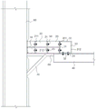
Fig. 1 is a longitudinal cross-sectional schematic view of a hanging beam connection node structure of the present invention.
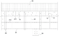
Fig. 2 is a transverse cross-section schematic view of the utility model relates to a hanging beam connected node structure.
Fig. 3 is a schematic view of the middle suspension beam of the present invention.
Description of reference numerals: a force transfer member 10; a weldment 11; a mounting plate 12; a steel purlin 20; h-shaped steel 21; a first side panel 211; a second side panel surface 212; a reinforcing plate 22; a mounting hole 23; a hanging beam 30; section steel 31; a first flange plate 311; a second flange plate 312; a bottom closure plate 32; a top closure plate 33; a hoisting hole 34; a cross member 40; a fastener 50; horizontal angle steel 60; angle steel 70 for diagonal bracing; the fender post 80.
Detailed Description
Reference will now be made in detail to the exemplary embodiments, examples of which are illustrated in the accompanying drawings. The following description refers to the accompanying drawings in which the same numbers in different drawings represent the same or similar elements unless otherwise indicated. The implementations described in the exemplary embodiments below are not intended to represent all implementations consistent with the present application, but are merely examples of apparatus and methods consistent with certain aspects of the present application.
The zigzag purlin component for foundation pit support according to the present application will be described in detail below with reference to the accompanying drawings. Features in the embodiments described below may be combined with each other without conflict.
The first embodiment is as follows: referring to fig. 1 to 3, the present application provides a hanging beam 30 connection node structure for connecting a cross beam 40 and a steel purlin 20, wherein the steel purlin 20 is connected to fender piles 80 through force transmission members 10, and the fender piles 80 are distributed around the periphery of a foundation pit. The steel purlin 20 is a rigid strip structure, and the length direction of the steel purlin is perpendicular to the length direction of the fender post 80.
The force transfer member 10 is fixed to the fender post 80, and the force transfer member 10 is made of steel. Optionally, the force transfer member 10 is welded to the fender post 80 to secure the two together. The welding position of the force transmission piece 10 on the fender post 80 can be flexibly adjusted to meet the installation height requirements of different cross beams 40. Optionally, the force transfer member 10 is embedded in a concrete beam, the concrete beam is connected to the fender pile 80, and the surface of the force transfer member 10 is exposed to the surface of the concrete beam.
In an alternative embodiment, the force transfer member 10 comprises a welding member 11 and a mounting plate 12 secured to the welding member 11, the mounting plate 12 being provided with spaced apart fastening holes. One end of the weldment 11 is welded to the fender post 80 so that the mounting plate 12 and fender post 80 are located at opposite ends of the weldment 11 facing away from each other, and the steel purlin 20 is lockingly connected to the mounting plate 12 by fasteners 50. Alternatively, the cross-section of the weldment 11 is configured in a cross-shaped configuration, a U-shaped configuration, or an H-shaped configuration.
The steel purlin 20 is detachably connected to the force transmission piece 10 through the fastener 50, and the steel purlin 20 is fixed to the force transmission piece 10, so that the steel purlin and the force transmission piece are integrally installed and fixedly connected. Wherein, every steel encloses purlin 20 and connects two and above biography power piece 10, realizes the multiple spot connection, and mounting structure intensity is high.
The hanging beam 30 is detachably connected to the steel purlin 20 through a fastener 50, and the hanging beam 30 is used for hoisting the connecting cross beam 40. The hanging beam 30 is a rigid structural member, and the mounting position of the hanging beam 30 can be adjusted by moving along the length direction of the steel purlin 20, so that the convenience in adjusting the mounting position of the hanging beam 30 is improved. The assembly position of the hanging beam 30 can be adjusted along the length direction of the steel purlin 20 so as to meet the requirements of different supporting positions and be convenient to operate. Further, the cross beams 40 extend from the hanging beam 30 to the position below the steel purlin 20, so that the connection stability of the hanging beam 30 and the cross beams 40 is improved. Crossbeam 40 extends to steel purlin 20 below to make crossbeam 40 and steel purlin 20 mutual lever support, overall structure is more stable.
In one embodiment, the steel purlin 20 includes an H-section steel 21, the H-section steel 21 having a first side panel surface 211 and a second side panel surface 212, a web connected between the first side panel surface 211 and the second side panel surface 212, and a stiffener 22. Wherein, first side face 211 and second side face 212 are parallel to each other, and the middle web is connected in the middle department of first side face 211 and second side face 212, and first side face 211, web and second side face 212 are connected to reinforcing plate 22 to constitute the additional strengthening that three sides are connected.
The first side plate surface 211 and the second side plate surface 212 of the H-shaped steel 21 which are parallel to each other are provided with through mounting holes 23, and the mounting holes 23 are used for assembling the fasteners 50. The first side plate surface 211 of the H-beam 21 is attached to the force transmission member 10 and locked with the force transmission member 10 by the fastening member 50, and the hanging beam 30 is connected to the second side plate surface 212 of the H-beam 21. The first side plate 211 is engaged with the mounting plate of the force transmitting member 10 and fixedly connected thereto by the fastening member 50. Optionally, the mounting hole 23 and the fixing hole are inserted and locked by the fastener 50, and the installation is convenient. Wherein the fastener 50 is configured as a high strength bolt assembly.
Further, the mounting holes 23 are a plurality of groups distributed at intervals along the length direction of the second side plate surface 212, and the hanging beam 30 is selected to be connected and fixed with one of the plurality of groups of mounting holes 23 along the length direction of the second side plate surface 212. Wherein, the position of the mounting hole 23 is adapted to the mounting position of the hanging beam 30, so as to conveniently and flexibly adjust the mounting position of the hanging beam 30.
In one embodiment, the steel purlins 20 comprise two steel purlins, two adjacent steel purlins 20 are connected by the fastener 50, the suspension beam 30 is connected to one of the steel purlins 20, and the other steel purlin 20 is connected to the force transmission member 10. The steel purlin 20 sets up two, both interconnect to adjust structural strength. Two steel purlins 20 are arranged, so that the connection strength can be improved, and the mounting position of the cross beam 40 can be adjusted. Optionally, two adjacent steel purlins 20 are locked and connected through the fastener 50, and the assembly and the adjustment are convenient.
Referring to fig. 1 to 3, the suspension beam 30 is used for connecting a cross beam 40, wherein the suspension beam 30 includes a steel section 31 and a bottom sealing plate 32 fixed on one end face of the steel section 31, the steel section 31 has two flange plates, i.e. a first flange plate 311 and a second flange plate 312, the bottom sealing plate 32 is connected to one end of the two flange plates 311, 312, the two flange plates 311, 312 and the bottom sealing plate 32 form a "u" shaped structure, and one of the two flange plates 311, 312 is connected to the steel purlin 20 through a fastener 50 to connect the suspension beam 30 to the steel purlin 20. The bottom closing plate 32 is provided with hoisting holes 34 distributed at intervals, and the fasteners 50 penetrate through the hoisting holes 34 and are connected with the cross beam 40. Further, the hanging beam 30 further comprises a top sealing plate 33 fixed on the other end surface of the section steel 31, and the top sealing plate 33 is flush with the surface of the steel purlin 20. The top shrouding 33 sets up with end shrouding 32 is relative, also be equipped with the hole for hoist on the top shrouding 33, the hole for hoist on the top shrouding 33 with hole for hoist 34 on the end shrouding 32 is just to setting up one by one, so can need not distinguish the top end when installing hanging beam 30, promotes the convenience of assembly.
The structural strength of the section steel 31 is high, the size of the section steel is stable, and the bottom sealing plate 32 is fixed on the section steel 31. The section steel 31 is configured in an H-shaped structure, that is, the section steel 31 further includes a web connected between the two flange plates 311 and 312, the top sealing plate and the bottom sealing plate. The hanger beam 30 further includes reinforcing ribs perpendicularly intersecting the web and connecting the top and bottom closure plates 33, 32, such that the hanger beam 30 has improved structural strength. The lateral direction of the steel section 31 is attached to the second side plate surface 212 of the steel purlin 20 through the fastener 50. The bottom closure plate 32 is located at the bottom of the steel section 31, and the bottom closure plate 32 is perpendicular to the second side plate surface 212, so as to adjust the installation angle of the cross beam 40.
For the stability that improves hanging beam 30 connected node structure, furtherly, hanging beam 30 connected node structure still includes bracket spare, and bracket spare includes fixed connection in fender post 80's horizontal angle steel 60 and connects in the bracing angle steel 70 of horizontal angle steel 60, and bracing angle steel 70 slope is connected between fender post 80 and horizontal angle steel 60, and horizontal angle steel 60 is erect in steel purlin 20. The horizontal angle iron 60 extends from the fender post 80 towards the steel purlin 20 to support the steel purlin 20 and thus the beam 40 and the structure to which the beam 40 is connected. A triangular support structure is formed between the diagonal angle steel 70 and the horizontal angle steel 60, and the structural stability is good.
Although the present application has been described with reference to a preferred embodiment, it should be understood that various changes, substitutions and alterations can be made herein without departing from the spirit and scope of the application, and all changes, substitutions and alterations that fall within the spirit and scope of the application are to be understood as being covered by the following claims.
Claims (10)

1.一种吊梁连接节点结构,用于将横梁吊装连接于钢围檩,其特征在于,所述吊梁连接节点结构包括吊梁,所述吊梁包括型钢和底封板,所述型钢具有两个翼缘板,所述底封板连接于所述两个翼缘板的一端处,所述两个翼缘板和所述底封板围成“凵”形结构,所述两个翼缘板的其中之一通过紧固件连接于所述钢围檩,以将所述吊梁连接于所述钢围檩,所述底封板上设有吊装孔,所述横梁通过紧固件贯穿所述吊装孔而连接于所述底封板,以吊装于所述吊梁下方。1. A hanging beam connection node structure is used for hoisting the cross beam to be connected to a steel purlin, it is characterized in that, the described hanging beam connection node structure comprises a hanging beam, and the hanging beam comprises a section steel and a bottom sealing plate, and the section steel There are two flange plates, the bottom sealing plate is connected to one end of the two flange plates, and the two flange plates and the bottom sealing plate form a "Zhong"-shaped structure, and the two One of the flange plates is connected to the steel purlin by fasteners, so as to connect the hanging beam to the steel purlin, the bottom cover plate is provided with a hoisting hole, and the cross beam is fastened by The component penetrates the hoisting hole and is connected to the bottom cover plate, so as to be hoisted under the suspending beam. 2.根据权利要求1所述的吊梁连接节点结构,其特征在于,所述吊梁还包括连接于所述型钢的另一端面处的顶封板,所述顶封板与所述钢围檩的表面平齐。2 . The hanging beam connection node structure according to claim 1 , wherein the hanging beam further comprises a top sealing plate connected to the other end face of the section steel, and the top sealing plate is connected to the steel enclosure. 3 . The surface of the purlin is flush. 3.根据权利要求2所述的吊梁连接节点结构,其特征在于,所述顶封板上也设有吊装孔,所述顶封板上的吊装孔与所述底封板上的吊装孔一一正对设置。3 . The hoisting beam connecting node structure according to claim 2 , wherein the top sealing plate is also provided with hoisting holes, the hoisting holes on the top sealing board and the hoisting holes on the bottom sealing board are 3 . Set up one by one. 4.根据权利要求3所述的吊梁连接节点结构,其特征在于,所述型钢包括连接于所述两个翼缘板、顶封板和底封板之间的腹板。4. The hanging beam connection node structure according to claim 3, wherein the shaped steel comprises a web connected between the two flange plates, the top cover plate and the bottom cover plate. 5.根据权利要求4所述的吊梁连接节点结构,其特征在于,所述吊梁还包括与所述腹板垂直相交,并连接所述顶封板和底封板的加强肋板。5. The hanging beam connecting node structure according to claim 4, characterized in that, the hanging beam further comprises a reinforcing rib that intersects with the web perpendicularly and connects the top sealing plate and the bottom sealing plate. 6.根据权利要求1所述的吊梁连接节点结构,其特征在于,所述横梁自所述吊梁延伸至所述钢围檩的下方。6 . The hanging beam connecting node structure according to claim 1 , wherein the cross beam extends from the hanging beam to below the steel purlin. 7 . 7.根据权利要求1所述的吊梁连接节点结构,其特征在于,所述钢围檩通过传力件连接至围护桩,所述钢围檩包括H型钢及连接所述H型钢的加强板,所述H型钢的相互平行的第一侧板面和第二侧板面均设置贯穿的安装孔,所述H型钢的第一侧板面贴合于所述传力件并通过紧固件与所述传力件锁固,所述吊梁连接于所述H型钢的第二侧板面。7 . The hanging beam connection node structure according to claim 1 , wherein the steel purlin is connected to the retaining pile through a force transmission member, and the steel purlin comprises an H-shaped steel and a reinforcement connecting the H-shaped steel. 8 . The first side plate surface and the second side plate surface of the H-shaped steel that are parallel to each other are provided with through installation holes, and the first side plate surface of the H-shaped steel is attached to the force transmission member and is fastened by The suspending beam is connected to the second side panel surface of the H-shaped steel. 8.根据权利要求7所述的吊梁连接节点结构,其特征在于,所述安装孔包括沿所述第二侧板面的长度方向间隔分布的多组,所述吊梁可在所述第二侧板面的长度方向择一与所述多组安装孔中的其中一组连接固定。8 . The hanging beam connection node structure according to claim 7 , wherein the installation holes comprise a plurality of groups spaced along the length direction of the second side panel, and the hanging beam can be installed in the second side panel. 9 . One of the length directions of the two side panels is selected to be connected and fixed with one of the plurality of sets of installation holes. 9.根据权利要求7所述的吊梁连接节点结构,其特征在于,所述钢围檩包括两根,相邻两根所述钢围檩通过紧固件连接,所述吊梁连接于其中一根钢围檩,另一根所述钢围檩连接于所述传力件。9 . The hanging beam connection node structure according to claim 7 , wherein the steel surrounding purlins comprise two, two adjacent steel surrounding purlins are connected by fasteners, and the hanging beams are connected therein. 10 . One steel purlin and the other said steel purlin are connected to the force transmission member. 10.根据权利要求7所述的吊梁连接节点结构,其特征在于,还包括固定连接于所述围护桩的水平角钢和连接于所述水平角钢的斜撑角钢,所述斜撑角钢倾斜连接于所述围护桩,所述钢围檩架设于所述水平角钢上。10. The hanging beam connection node structure according to claim 7, characterized in that, further comprising a horizontal angle steel fixedly connected to the enclosure pile and a diagonal bracing angle steel connected to the horizontal angle steel, the diagonal bracing angle steel being inclined Connected to the enclosure pile, the steel enclosure purlin is erected on the horizontal angle steel.
CN202220579278.9U 2022-03-16 2022-03-16 Hanging beam connecting node structure Withdrawn - After Issue CN217267515U (en)

Priority Applications (1)

Application Number Priority Date Filing Date Title
CN202220579278.9U CN217267515U (en) 2022-03-16 2022-03-16 Hanging beam connecting node structure

Applications Claiming Priority (1)

Application Number Priority Date Filing Date Title
CN202220579278.9U CN217267515U (en) 2022-03-16 2022-03-16 Hanging beam connecting node structure

Publications (1)

Publication Number Publication Date
CN217267515U true CN217267515U (en) 2022-08-23

Family

ID=82870264

Family Applications (1)

Application Number Title Priority Date Filing Date
CN202220579278.9U Withdrawn - After Issue CN217267515U (en) 2022-03-16 2022-03-16 Hanging beam connecting node structure

Country Status (1)

Country Link
CN (1) CN217267515U (en)

Cited By (1)

* Cited by examiner, † Cited by third party
Publication number Priority date Publication date Assignee Title
CN114809002A (en) * 2022-03-16 2022-07-29 东通岩土科技股份有限公司 Hanging beam connecting node structure

Cited By (2)

* Cited by examiner, † Cited by third party
Publication number Priority date Publication date Assignee Title
CN114809002A (en) * 2022-03-16 2022-07-29 东通岩土科技股份有限公司 Hanging beam connecting node structure
CN114809002B (en) * 2022-03-16 2026-06-05 东通岩土科技股份有限公司 A type of suspension beam connection node structure

Similar Documents

Publication Publication Date Title
KR102079008B1 (en) E-z connecting structure for beam and column wherein the end-moment and bending resistibility are reinforced
WO2016077943A1 (en) Building supporting unit and building supporting structure employing same
CN215212568U (en) Reassembling type steel frame composite sheet house
CN213805443U (en) Steel structure, frame beam structure, slope reinforcement structure and reinforcement support structure
KR102252648B1 (en) Structure Of Assemble For Steel Frame
CN212802449U (en) Non-pre-buried cantilever steel beam
CN116771025A (en) Assembled adjustable conversion layer system
CN215329999U (en) Pile group type tower crane foundation
CN204080843U (en) Movable plank house foundation structure
CN215887884U (en) Be applied to bailey frame steel trestle of deep basal pit construction
CN213390842U (en) Local bearing and supporting structure of steel truss
CN214696891U (en) Pin-connected panel unilateral wall form shaped steel support
CN113684766A (en) A construction platform for bridge main tower corbel and construction method thereof
CN222333364U (en) A temporary support structure for corrugated steel plate floor construction
CN211872631U (en) Connecting device for bridge panels
KR20060036630A (en) Connection structure of brace and bending reinforcement for reinforcing connection
KR20180118414A (en) Tunnel soundproofed wall having steel pipe connecting part
CN112049415A (en) Construction method of cornice formwork
JP2018162607A (en) Floor panel, floor structure, floor structure construction method and floor structure reuse method
CN217948778U (en) Landing stage panel and landing stage
CN114809002A (en) Hanging beam connecting node structure
CN215801686U (en) Steel support mounting system
CN108502670A (en) A kind of assembled elevator mine timbering
JP2690868B2 (en) Building steel foundation
CN103452109B (en) Installing device for steel strand anchors in inner support system of foundation pit support

Legal Events

Date Code Title Description
GR01 Patent grant
GR01 Patent grant
EE01 Entry into force of recordation of patent licensing contract

Assignee: Zhejiang Zhefeng Engineering Consulting Co.,Ltd.

Assignor: Dongtong Geotechnical Science and Technology Inc.

Contract record no.: X2025980000660

Denomination of utility model: A suspended beam connection node structure

Granted publication date: 20220823

License type: Common License

Record date: 20250109

Assignee: Hangzhou Dongtong Construction Engineering Co.,Ltd.

Assignor: Dongtong Geotechnical Science and Technology Inc.

Contract record no.: X2025980000658

Denomination of utility model: A suspended beam connection node structure

Granted publication date: 20220823

License type: Common License

Record date: 20250109

EE01 Entry into force of recordation of patent licensing contract
AV01 Patent right actively abandoned

Granted publication date: 20220823

Effective date of abandoning: 20260605

AV01 Patent right actively abandoned

Granted publication date: 20220823

Effective date of abandoning: 20260605

AV01 Patent right actively abandoned