CN217260072U - Vehicle steering mechanism for rail transit - Google Patents
Vehicle steering mechanism for rail transit Download PDFInfo
- Publication number
- CN217260072U CN217260072U CN202122929583.4U CN202122929583U CN217260072U CN 217260072 U CN217260072 U CN 217260072U CN 202122929583 U CN202122929583 U CN 202122929583U CN 217260072 U CN217260072 U CN 217260072U
- Authority
- CN
- China
- Prior art keywords
- track
- steering mechanism
- fixedly connected
- fixed surface
- vehicle steering
- Prior art date
- Legal status (The legal status is an assumption and is not a legal conclusion. Google has not performed a legal analysis and makes no representation as to the accuracy of the status listed.)
- Expired - Fee Related
Links
- 230000001681 protective effect Effects 0.000 abstract description 7
- 230000000694 effects Effects 0.000 abstract description 5
- 238000009434 installation Methods 0.000 abstract description 3
- 239000003921 oil Substances 0.000 description 16
- 238000000034 method Methods 0.000 description 8
- 239000010687 lubricating oil Substances 0.000 description 4
- 230000007774 longterm Effects 0.000 description 3
- 230000009286 beneficial effect Effects 0.000 description 2
- 238000012423 maintenance Methods 0.000 description 2
- 238000004519 manufacturing process Methods 0.000 description 2
- 238000012986 modification Methods 0.000 description 2
- 230000004048 modification Effects 0.000 description 2
- 238000010276 construction Methods 0.000 description 1
- 238000010586 diagram Methods 0.000 description 1
- 238000005516 engineering process Methods 0.000 description 1
- 230000002708 enhancing effect Effects 0.000 description 1
- 239000000463 material Substances 0.000 description 1
- 238000003032 molecular docking Methods 0.000 description 1
- 229910001220 stainless steel Inorganic materials 0.000 description 1
- 239000010935 stainless steel Substances 0.000 description 1
Images


Landscapes
- Vehicle Cleaning, Maintenance, Repair, Refitting, And Outriggers (AREA)
Abstract
Description
技术领域technical field
本实用新型涉及轨道运输技术领域,具体为一种轨道交通用车辆转向机构。The utility model relates to the technical field of rail transportation, in particular to a vehicle steering mechanism for rail transportation.
背景技术Background technique
轨道运输作为小断面隧道、巷道施工中一种常用的运输方式,具有投入小、占地小、安装拆卸方便、运输速度等优点,但是小断面隧道、巷道施工的轨道在交叉和分叉时有一定的难度,通常采用道岔来解决,小断面隧道、巷道轨道运输转弯所需轨迹半径较大,尤其是直角转弯难以解决。As a common transportation method in the construction of small-section tunnels and roadways, rail transportation has the advantages of small investment, small footprint, convenient installation and disassembly, and transportation speed. A certain degree of difficulty is usually solved by turnouts. The track radius required for small-section tunnels and roadway rail transportation turns is relatively large, especially right-angle turns are difficult to solve.
在中国实用新型专利申请号:201720919106.0中公开有一种轨道转向装置,该轨道转向装置,转盘、轨道底盘和用于与轨道对接的第一导轨,所述转盘可转动地安装在所述轨道底盘上,所述第一导轨固定在所述转盘上,利用本实用新型实施例无需挖设辅助运输巷道和另外铺设轨道,可减少工作量,降低劳动强度,节约生产成本,增加生产过程中的安全系数,而且该轨道转向装置结构简单,安装方便,该轨道转向装置,在使用时,无法对轨道的高度进行微调,当与其他轨道高度不一致时,需要重新拆卸安装,费时费力,并且在长期的转向中,无法对转向机构进行简单的保养,从而装置的使用寿命大幅降低。In China Utility Model Patent Application No.: 201720919106.0, there is disclosed a track steering device, the track steering device, a turntable, a track chassis and a first guide rail for docking with a track, and the turntable is rotatably mounted on the track chassis , the first guide rail is fixed on the turntable, the use of the embodiment of the present utility model does not require digging auxiliary transportation tunnels and laying additional tracks, which can reduce workload, reduce labor intensity, save production costs, and increase the safety factor in the production process. , and the track steering device has a simple structure and is easy to install. The track steering device cannot be used to fine-tune the height of the track. When the height of the track is inconsistent with other tracks, it needs to be disassembled and installed again, which is time-consuming and laborious. In this case, simple maintenance of the steering mechanism is not possible, so the service life of the device is greatly reduced.
因此,提出一种轨道交通用车辆转向机构来解决上述问题很有必要。Therefore, it is necessary to propose a steering mechanism for rail transit vehicles to solve the above problems.
实用新型内容Utility model content
(一)解决的技术问题(1) Technical problems solved
本实用新型的目的在于提供一种轨道交通用车辆转向机构,以解决上述背景技术中提出的现有的在使用时,无法对轨道的高度进行微调,当与其他轨道高度不一致时,需要重新拆卸安装,费时费力,并且在长期的转向中,无法对转向机构进行简单的保养,从而装置的使用寿命大幅降低的问题。The purpose of the present utility model is to provide a steering mechanism for rail transit vehicles, so as to solve the problem of the existing problem in the above-mentioned background technology that the height of the track cannot be fine-tuned during use, and when the height of the track is inconsistent with other track heights, it needs to be disassembled again. Installation is time-consuming and labor-intensive, and in the long-term steering, simple maintenance of the steering mechanism cannot be performed, so the service life of the device is greatly reduced.
(二)技术方案(2) Technical solutions
为实现以上目的,本实用新型通过以下技术方案予以实现:一种轨道交通用车辆转向机构,包括轨道板和底板,所述轨道板的下表面固定连接有蜗杆,所述底板的上表面固定连接有承接柱,所述承接柱的顶端固定连接有保护箱,所述保护壳的表面固定连接有第一电机,所述轨道板的一侧表面固定连接有油管,所述油管的顶端活动连接有帽盖。In order to achieve the above purpose, the present invention is achieved through the following technical solutions: a steering mechanism for rail transit vehicles, comprising a rail plate and a bottom plate, the lower surface of the rail plate is fixedly connected with a worm, and the upper surface of the bottom plate is fixedly connected There is a receiving column, the top of the receiving column is fixedly connected with a protective box, the surface of the protective shell is fixedly connected with a first motor, a side surface of the track plate is fixedly connected with an oil pipe, and the top of the oil pipe is movably connected with a cap.
优选的,所述轨道板的上表面固定连接有轨道,所述轨道的长度与轨道板的长度相等。Preferably, a track is fixedly connected to the upper surface of the track plate, and the length of the track is equal to the length of the track plate.
优选的,所述轨道板的下表面固定连接有伸缩杆,所述伸缩杆的数量为四个,四个所述伸缩杆的底端均固定连接有大齿轮。Preferably, telescopic rods are fixedly connected to the lower surface of the track plate, the number of the telescopic rods is four, and the bottom ends of the four telescopic rods are fixedly connected with large gears.
优选的,所述底板的上表面固定连接有第二电机,所述第二电机的上部活动连接有转轴。Preferably, a second motor is fixedly connected to the upper surface of the bottom plate, and a rotating shaft is movably connected to the upper part of the second motor.
优选的,所述转轴的一端固定连接有小齿轮,所述转轴的直径为一厘米。Preferably, a pinion is fixedly connected to one end of the rotating shaft, and the diameter of the rotating shaft is one centimeter.
优选的,所述第一电机的输出轴贯穿保护箱并固定连接有蜗轮,所述蜗杆的底端贯穿保护箱并与蜗轮的一端啮合连接。Preferably, the output shaft of the first motor penetrates the protective box and is fixedly connected with a worm wheel, and the bottom end of the worm screw penetrates the protective box and is engaged with one end of the worm wheel.
优选的,所述底板的下表面活动连接有支撑柱,所述支撑柱的厚度为五厘米。Preferably, a support column is movably connected to the lower surface of the bottom plate, and the thickness of the support column is five centimeters.
(三)有益效果(3) Beneficial effects
与现有技术相比,本实用新型提供了一种轨道交通用车辆转向机构,具备以下有益效果:Compared with the prior art, the utility model provides a vehicle steering mechanism for rail transit, which has the following beneficial effects:
1、该轨道交通用车辆转向机构,通过在保护箱的表面安装第一电机,实现了给蜗轮转动提供动力的效果,通过蜗轮的转动,使蜗杆能进行上下匀速运动,并带动轨道板和轨道上下匀速运动,从而解决了无法对轨道的高度进行微调,当与其他导轨高度不一致时,需要重新拆卸安装,费时费力的问题。1. The steering mechanism of the rail transit vehicle, by installing the first motor on the surface of the protective box, realizes the effect of providing power for the rotation of the worm wheel. It moves up and down at a uniform speed, which solves the problem that the height of the rail cannot be fine-tuned. When the height of the rail is inconsistent with other rails, it needs to be disassembled and installed again, which is time-consuming and labor-intensive.
2、该轨道交通用车辆转向机构,通过在轨道板的一侧表面固定安装油管,使倒入油管的润滑油能够顺利的到达小齿轮的表面,达到了保养小齿轮的目的,并通过在油管进口的顶部安装盖帽,有效的避免了其他杂物进入油管,从而解决了在长期的转向中,无法对转向机构进行简单的保养,从而装置的使用寿命大幅降低的问题。2. The steering mechanism of the rail transit vehicle, by fixing the oil pipe on one side surface of the rail plate, enables the lubricating oil poured into the oil pipe to reach the surface of the pinion smoothly, and achieves the purpose of maintaining the pinion. The imported top is installed with a cap, which effectively prevents other debris from entering the oil pipe, thus solving the problem that the steering mechanism cannot be easily maintained during long-term steering, thus greatly reducing the service life of the device.
附图说明Description of drawings
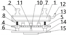
图1为本实用新型结构立体示意图;Fig. 1 is the three-dimensional schematic diagram of the structure of the utility model;
图2为本实用新型结构俯视剖面示意图;Figure 2 is a schematic top view cross-sectional view of the structure of the utility model;
图3为本实用新型结构正视示意图;3 is a schematic front view of the structure of the utility model;
图4为本实用新型结构左视示意图。FIG. 4 is a left side view of the structure of the utility model.
图中:1、轨道板;2、轨道;3、蜗杆;4、保护箱;5、第一电机;6、承接柱;7、伸缩杆;8、大齿轮;9、小齿轮;10、第二电机;11、转轴;12、帽盖;13、油管;14、底板;15、支撑柱。In the picture: 1. Track plate; 2. Track; 3. Worm; 4. Protective box; 5. The first motor; 6. Receiving column; 7. Telescopic rod; 8. Large gear; 9. Small gear; Two motor; 11, shaft; 12, cap; 13, oil pipe; 14, bottom plate; 15, support column.
具体实施方式Detailed ways
下面将结合本实用新型实施例中的附图,对本实用新型实施例中的技术方案进行清楚、完整地描述,显然,所描述的实施例仅仅是本实用新型一部分实施例,而不是全部的实施例。基于本实用新型中的实施例,本领域普通技术人员在没有做出创造性劳动前提下所获得的所有其他实施例,都属于本实用新型保护的范围。The technical solutions in the embodiments of the present utility model will be clearly and completely described below with reference to the accompanying drawings in the embodiments of the present utility model. Obviously, the described embodiments are only a part of the embodiments of the present utility model, rather than all the implementations. example. Based on the embodiments of the present invention, all other embodiments obtained by those of ordinary skill in the art without creative work fall within the protection scope of the present invention.
请参阅图1-4所示,一种轨道交通用车辆转向机构,包括轨道板1和底板14,底板14的下表面活动连接有支撑柱15,支撑柱15的厚度为五厘米,支撑柱15的下表面设有防滑垫,从而增强了支撑柱15在地面的稳定性,使得底板14能够更稳定的在支撑柱15上旋转,底板14的上表面固定连接有第二电机10,第二电机10的上部活动连接有转轴11,转轴11的一端固定连接有小齿轮9,转轴11的直径为一厘米,转轴11的材质为不锈钢,通过第二电机10的工作,带动转轴11的旋转,从而带动小齿轮9的旋转,达到了让小齿轮9的旋转变得更简单省力的目的,轨道板1的上表面固定连接有轨道2,轨道2的长度与轨道板1的长度相等,轨道板1的下表面固定连接有伸缩杆 7,伸缩杆7的数量为四个,四个伸缩杆7的底端均固定连接有大齿轮8,四个大齿轮8的大小形状相同,小齿轮9与四个大齿轮8相互适配,通过小齿轮9的转动,将带动四个大齿轮8一起转动,通过大齿轮8的转动,达到了让轨道2转动的目的,轨道板1的下表面固定连接有蜗杆3,底板14的上表面固定连接有承接柱6,承接柱6的顶端固定连接有保护箱4,保护箱4的表面固定连接有第一电机5,第一电机5的输出轴贯穿保护箱4并固定连接有蜗轮,蜗杆3的底端贯穿保护箱4并与蜗轮的一端啮合连接,底板14的四个顶角处均设置有承接柱6,四个承接柱6的顶部均安装有保护箱4,四个保护箱 4的表面均安装有第一电机5和蜗杆3,蜗杆3的直径为三厘米,通过四个蜗杆3的共同运动,使整个装置更加稳定,通过在底板14的表面固定连接承接柱6,达到了支撑保护箱4的效果,通过在承接柱6的上部固定安装保护箱 4,实现了保护蜗杆3和蜗轮的作用,通过在保护箱4的表面安装第一电机5,实现了给蜗轮转动提供动力的效果,通过蜗轮的转动,使蜗杆3能进行上下匀速运动,并带动轨道板1和轨道2上下匀速运动,从而解决了无法对轨道2 的高度进行微调,当与其他导轨高度不一致时,需要重新拆卸安装,费时费力的问题,轨道板1的一侧表面固定连接有油管13,油管13的顶端活动连接有帽盖12,通过在轨道板1的一侧表面固定安装油管13进口,并在小齿轮9正上方的轨道板下1表面安装油管13出口,使倒入油管13的润滑油能够顺利的到达小齿轮9的表面,达到了保养小齿轮9的目的,并通过在油管13进口的顶部安装帽盖12,有效的避免了其他杂物进入油管13,通过设置油管13,从而解决了在长期的转向中,无法对转向机构进行简单的保养,从而装置的使用寿命大幅降低的问题。Please refer to FIGS. 1-4 , a steering mechanism for a rail transit vehicle, including a
该文中出现的电器元件均与外界的主控器及220V市电电连接,并且主控器可为计算机等起到控制的常规已知设备。The electrical components appearing in this article are all connected with the external main controller and 220V mains, and the main controller can be a conventional known device controlled by a computer or the like.
工作原理:首先将装置安放在导轨的拐弯处,确保支撑柱15与地面保持水平的位置,然后启动安装在保护箱4表面的第一电机5,保护箱4在承接柱 6的支柱下,能够一直保持平稳,第一电机5将带动保护箱4内的蜗轮进行转动,蜗轮的转动将带动蜗杆3的运动,从而使轨道板1和轨道2能够进行上下微调,伸缩杆7也会随着进行伸缩运动,从而使轨道2与导轨能够处于同一高度,然后将运输车停放在轨道板1上,然后打开帽盖12,将润滑油倒入油管13内,润滑油通过油管13到达小齿轮9表面,然后启动第二电机10,第二电机10通过带动转轴11进行转动,转轴11通过与小齿轮9固定连接,将带动小齿轮9转动,小齿轮9转动会带动四个大齿轮8的转动,大齿轮8通过与伸缩杆7固定连接,实现了带动底板14在支撑柱15上转动的效果,从而使轨道2能与导轨进行连接,然后运输车就可以从轨道板1上到达导轨处,从而运输车实现了转弯的目的。Working principle: first place the device at the corner of the guide rail to ensure that the
需要说明的是,在本文中,诸如第一和第二等之类的关系术语仅仅用来将一个实体或者操作与另一个实体或操作区分开来,而不一定要求或者暗示这些实体或操作之间存在任何这种实际的关系或者顺序。而且,术语“包括”、“包含”或者其任何其他变体意在涵盖非排他性的包含,从而使得包括一系列要素的过程、方法、物品或者设备不仅包括那些要素,而且还包括没有明确列出的其他要素,或者是还包括为这种过程、方法、物品或者设备所固有的要素。在没有更多限制的情况下,由语句“包括一个……”限定的要素,并不排除在包括所述要素的过程、方法、物品或者设备中还存在另外的相同要素。It should be noted that, in this document, relational terms such as first and second are only used to distinguish one entity or operation from another entity or operation, and do not necessarily require or imply any relationship between these entities or operations. any such actual relationship or sequence exists. Moreover, the terms "comprising", "comprising" or any other variation thereof are intended to encompass a non-exclusive inclusion such that a process, method, article or device that includes a list of elements includes not only those elements, but also includes not explicitly listed or other elements inherent to such a process, method, article or apparatus. Without further limitation, an element qualified by the phrase "comprising a..." does not preclude the presence of additional identical elements in a process, method, article or apparatus that includes the element.
尽管已经示出和描述了本实用新型的实施例,对于本领域的普通技术人员而言,可以理解在不脱离本实用新型的原理和精神的情况下可以对这些实施例进行多种变化、修改、替换和变型,本实用新型的范围由所附权利要求及其等同物限定。Although the embodiments of the present invention have been shown and described, it will be understood by those skilled in the art that various changes and modifications can be made to these embodiments without departing from the principles and spirit of the present invention , alternatives and modifications, the scope of the present invention is defined by the appended claims and their equivalents.
Claims (7)
Priority Applications (1)
| Application Number | Priority Date | Filing Date | Title |
|---|---|---|---|
| CN202122929583.4U CN217260072U (en) | 2021-11-26 | 2021-11-26 | Vehicle steering mechanism for rail transit |
Applications Claiming Priority (1)
| Application Number | Priority Date | Filing Date | Title |
|---|---|---|---|
| CN202122929583.4U CN217260072U (en) | 2021-11-26 | 2021-11-26 | Vehicle steering mechanism for rail transit |
Publications (1)
| Publication Number | Publication Date |
|---|---|
| CN217260072U true CN217260072U (en) | 2022-08-23 |
Family
ID=82882877
Family Applications (1)
| Application Number | Title | Priority Date | Filing Date |
|---|---|---|---|
| CN202122929583.4U Expired - Fee Related CN217260072U (en) | 2021-11-26 | 2021-11-26 | Vehicle steering mechanism for rail transit |
Country Status (1)
| Country | Link |
|---|---|
| CN (1) | CN217260072U (en) |
-
2021
- 2021-11-26 CN CN202122929583.4U patent/CN217260072U/en not_active Expired - Fee Related
Similar Documents
| Publication | Publication Date | Title |
|---|---|---|
| CN209654059U (en) | A coal mine underground roadway support device | |
| CN217072624U (en) | Outer wall heat preservation location cutting device for building | |
| CN215594899U (en) | Supporting template for constructional engineering | |
| CN218788221U (en) | Face early warning device of frontier defense in construction | |
| CN218117299U (en) | Assembly type structure telescopic support frame for civil engineering | |
| CN209261189U (en) | A kind of construction site self-powered platform | |
| CN113941563B (en) | High altitude transformer dust collector | |
| CN111335239A (en) | Prevent muddy earth for road ponding processing apparatus that emptys | |
| CN217650265U (en) | Material transportation device for paving steel box girder bridge deck | |
| CN211395389U (en) | A kind of highway bridge construction equipment | |
| CN216042840U (en) | Ancient building protection strutting arrangement | |
| CN213703925U (en) | Automatic material distributing machine suitable for production of high-efficiency PC (polycarbonate) component | |
| CN211312764U (en) | An underground pipe gallery construction tooling | |
| CN216809597U (en) | Novel formwork support frame is used in public road bridge roof beam construction | |
| CN220889551U (en) | Auxiliary fixing device for embedded bolt | |
| CN221918998U (en) | A bridge and culvert construction installation frame | |
| CN219043871U (en) | Maintenance auxiliary equipment | |
| CN219618195U (en) | A slotting device for electrical piping | |
| CN113931190B (en) | Power station inclined plane construction slip form safety platform | |
| CN219622728U (en) | A support device for subway engineering construction | |
| CN217924715U (en) | Scaffold for building | |
| CN217841722U (en) | Mining area is with watering dust device | |
| CN222255269U (en) | Small-section movable support trolley for pipe gallery construction | |
| CN216999854U (en) | Underground pipe gallery construction protection device | |
| CN218436549U (en) | Town road crack patching device |
Legal Events
| Date | Code | Title | Description |
|---|---|---|---|
| GR01 | Patent grant | ||
| GR01 | Patent grant | ||
| CF01 | Termination of patent right due to non-payment of annual fee | ||
| CF01 | Termination of patent right due to non-payment of annual fee |
Granted publication date: 20220823 |