CN217226479U - Novel double-color mould - Google Patents
Novel double-color mould Download PDFInfo
- Publication number
- CN217226479U CN217226479U CN202220766983.XU CN202220766983U CN217226479U CN 217226479 U CN217226479 U CN 217226479U CN 202220766983 U CN202220766983 U CN 202220766983U CN 217226479 U CN217226479 U CN 217226479U
- Authority
- CN
- China
- Prior art keywords
- plate
- rotary
- ejector
- sliding
- core
- Prior art date
- Legal status (The legal status is an assumption and is not a legal conclusion. Google has not performed a legal analysis and makes no representation as to the accuracy of the status listed.)
- Active
Links
- 238000000465 moulding Methods 0.000 claims abstract description 15
- 239000003292 glue Substances 0.000 claims abstract description 11
- 238000002347 injection Methods 0.000 claims description 11
- 239000007924 injection Substances 0.000 claims description 11
- 230000000149 penetrating effect Effects 0.000 claims 2
- 239000000463 material Substances 0.000 abstract description 13
- 239000004033 plastic Substances 0.000 abstract description 12
- 229920003023 plastic Polymers 0.000 abstract description 12
- 238000013461 design Methods 0.000 abstract description 6
- 238000007493 shaping process Methods 0.000 abstract 3
- 238000001746 injection moulding Methods 0.000 description 5
- 230000006978 adaptation Effects 0.000 description 3
- 238000013459 approach Methods 0.000 description 3
- 239000003086 colorant Substances 0.000 description 1
- 238000007796 conventional method Methods 0.000 description 1
- 238000005516 engineering process Methods 0.000 description 1
- 238000000034 method Methods 0.000 description 1
- 238000012986 modification Methods 0.000 description 1
- 230000004048 modification Effects 0.000 description 1
- 239000002991 molded plastic Substances 0.000 description 1
- 239000000243 solution Substances 0.000 description 1
Images


Classifications
-
- Y—GENERAL TAGGING OF NEW TECHNOLOGICAL DEVELOPMENTS; GENERAL TAGGING OF CROSS-SECTIONAL TECHNOLOGIES SPANNING OVER SEVERAL SECTIONS OF THE IPC; TECHNICAL SUBJECTS COVERED BY FORMER USPC CROSS-REFERENCE ART COLLECTIONS [XRACs] AND DIGESTS
- Y02—TECHNOLOGIES OR APPLICATIONS FOR MITIGATION OR ADAPTATION AGAINST CLIMATE CHANGE
- Y02E—REDUCTION OF GREENHOUSE GAS [GHG] EMISSIONS, RELATED TO ENERGY GENERATION, TRANSMISSION OR DISTRIBUTION
- Y02E60/00—Enabling technologies; Technologies with a potential or indirect contribution to GHG emissions mitigation
- Y02E60/10—Energy storage using batteries
Landscapes
- Injection Moulding Of Plastics Or The Like (AREA)
- Moulds For Moulding Plastics Or The Like (AREA)
Abstract
The utility model aims at providing a new-type double-colored mould, it includes the cope match-plate pattern, lower bolster and rotating assembly, two injecting glue holes have been seted up in the cope match-plate pattern respectively, the bottom surface of locating the cope match-plate pattern is detained to the lower bolster, it is provided with the slide to slide in the lower bolster, rotating assembly includes rotary die core and rotary driving piece, rotary die core rotates and sets up on the slide, and rotary die core is located between lower bolster and the cope match-plate pattern, set up the shaping groove of two settings in opposite directions on the rotary die core respectively, rotary driving piece sets up on the slide, and rotary driving piece's output shaft is connected with rotary die core, when rotary driving piece is used for driving rotary die core and rotates, so that two shaping grooves communicate with two injecting glue holes respectively. So, through the double-colored plastic finished product of shaping in a mould, can reduce the repetition rate of mould part for mould structure is compacter, reduces material cost, and the structure is compacter moreover, thereby reduces the mould design degree of difficulty. The utility model discloses can be applied to the field of moulding plastics.
Description
Technical Field
The utility model relates to an injection mold's technical field especially relates to a new-type double-colored mould.
Background
As mold technology matures, people put new demands on injection molded parts, and in order to make products have two different layered colors, double-color molds are designed. The double-color mold is a mold which is formed by injecting two plastic materials on the same injection molding machine and molding the two plastic materials at two sides, but the product is only subjected to mold stripping once. Two-color molds often require the use of a special two-color injection molding machine.
The structure of the current two-color mold is as follows: a set of double-colored mould contains two moulds, and wherein two public mould shapes are the same completely, and two master model shapes are different, and two public moulds all can cooperate with two master models respectively and constitute complete mould. When the male die is used, the two female dies are of fixed mounting structures, and the two male dies are driven by the driving mechanism to rotate 180 degrees at each time to be respectively buckled with the two female dies.
However, the conventional method of driving the two male dies to rotate has the following problems that firstly, the two male dies are different from the male die core, and most of the other parts are the same, so that the two male dies can cause the repetition of a certain number of die parts, and the material cost of the double-color die is overlarge; secondly, two public moulds respectively with two master model cooperations constitute complete moulds, can increase the mould complex degree of difficulty, can increase the design degree of difficulty of mould mounting bracket. Therefore, a novel double-color mold is designed, so that the material repetition rate of the two molds is reduced to reduce the cost input, and the reduction of the mold design difficulty is the technical problem to be solved by the technical personnel in the field.
SUMMERY OF THE UTILITY MODEL
The utility model aims at overcoming the weak point among the prior art, providing a material repetition rate that can reduce double-colored mould drops into with reduce cost, can also reduce the new-type double-colored mould of the mould design degree of difficulty simultaneously.
The purpose of the utility model is realized through the following technical scheme:
a new bicolor mold comprising:
the upper die plate is internally provided with two glue injection holes respectively;
the lower template is buckled on the bottom surface of the upper template, and a sliding seat is arranged in the lower template in a sliding manner; and
the rotary component comprises a rotary mold core and a rotary driving piece, the rotary mold core is rotatably arranged on the sliding seat, the rotary mold core is located between the lower mold plate and the upper mold plate, two forming grooves which are oppositely arranged are respectively formed in the rotary mold core, the rotary driving piece is arranged on the sliding seat, an output shaft of the rotary driving piece is connected with the rotary mold core, and the rotary driving piece is used for driving the rotary mold core to rotate so that the forming grooves are respectively communicated with the two glue injection holes.
Preferably, the sliding seat includes a sliding plate, a seat body and a plurality of guide posts, each of the guide posts is respectively disposed in the lower mold plate, and each of the guide posts is disposed through the sliding plate, so that the sliding plate slides along each of the guide posts to be close to or away from the upper mold plate, the seat body is disposed on the sliding plate, the seat body is disposed through the lower mold plate, and the rotary mold core is rotatably disposed on the seat body.
Preferably, the rotary driving part includes cylinder, rack, gear and column spinner, the column spinner wears to locate in the seat body, rotary mold core set up in on the column spinner, the gear cover is located on the lateral wall of column spinner, the rack slide set up in on the slide, just the rack with the gear meshes mutually, the cylinder set up in on the slide, just the output shaft of cylinder with rack fixed connection.
Preferably, the rotary mold core comprises a core plate, an ejector plate and two ejector pieces, the core plate is arranged on the rotary column, the two ejector pieces are respectively arranged in the core plate in a sliding manner, the two ejector pieces are respectively arranged towards the two forming grooves, the ejector plate is arranged in the core plate in a sliding manner, and the ejector plate is used for ejecting one of the ejector pieces.
Preferably, the ejector includes a slider, a spring, and an ejector pin, the slider is slidably disposed in the core plate, one end of the ejector pin is fixedly disposed on the slider, the other end of the ejector pin penetrates through the core plate, so that the ejector pin faces the forming groove, and the spring is respectively abutted to the slider and the core plate, so that the ejector pin is far away from the forming groove.
Preferably, the ejection part further comprises a guide rod, the guide rod is arranged in the core plate, the guide rod penetrates through the ejector plate, and the spring is sleeved on the guide rod.
Preferably, the number of the springs is two, and a space is arranged between the two springs.
Preferably, a sliding groove is formed in the core plate, and the ejector plate is slidably arranged in the sliding groove.
Preferably, the sliding seat further comprises a pushing cylinder and a pushing block, the pushing cylinder is arranged on the seat body, the pushing block is arranged on an output shaft of the pushing cylinder, and the pushing block abuts against the ejector plate.
Preferably, a waist-shaped hole is formed in the ejector plate, and the rotating column penetrates through the waist-shaped hole.
Compared with the prior art, the utility model discloses at least, following advantage has:
1. the rotary mold cores are driven to rotate by the rotary driving piece, so that the rotary mold cores can be shared in one mold, the reuse rate of parts can be improved, the same mold parts can be greatly saved, and the material cost of the mold can be reduced; and the structure is more compact by realizing rotary adaptation in the same die, thereby effectively reducing the design difficulty of the double-color die.
Drawings
In order to more clearly illustrate the technical solutions of the embodiments of the present invention, the drawings required for the embodiments will be briefly described below, it should be understood that the following drawings only illustrate some embodiments of the present invention, and therefore should not be considered as limiting the scope, and that those skilled in the art can also obtain other related drawings based on these drawings without inventive efforts.
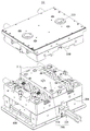
Fig. 1 is a schematic structural view of a novel two-color mold according to an embodiment of the present invention;
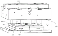
FIG. 2 is a partial schematic structural view of the novel two-color mold shown in FIG. 1;
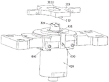
FIG. 3 is a partial schematic view of another angle of the new two-color mold shown in FIG. 1;
fig. 4 is a schematic partial structure view of a rotary mold core according to an embodiment of the present invention;
fig. 5 is a partial structural view of another angle of the new two-color mold shown in fig. 1.
Detailed Description
In order to facilitate understanding of the present invention, the present invention will be described more fully hereinafter with reference to the accompanying drawings. The preferred embodiments of the present invention are shown in the drawings.
Referring to fig. 1 and 2, a novel two-color mold 10 includes an upper mold plate 100, a lower mold plate 200, and a rotating assembly 300, two glue injection holes 110 are respectively formed in the upper mold plate 100, the lower mold plate 200 is buckled on the bottom surface of the upper mold plate 100, a sliding seat 400 is slidably disposed in the lower mold plate 200, the rotating assembly 300 includes a rotating mold core 310 and a rotating driving member 320, the rotating mold core 310 is rotatably disposed on the sliding seat 400, the rotating mold core 310 is located between the lower mold plate 200 and the upper mold plate 100, two opposite forming grooves 311 are respectively formed in the rotating mold core 310, the rotating driving member 320 is disposed on the sliding seat 400, an output shaft of the rotating driving member 320 is connected to the rotating mold core 310, and the rotating driving member 320 is used for driving the rotating mold core 310 to rotate, so that the two forming grooves 311 are respectively communicated with the two glue injection holes 110.
It should be noted that the upper plate 100 is provided with glue injection holes 110 for respectively injecting two different plastic materials. The lower plate 200 is adapted to be snap-fitted to the upper plate 100. Wherein a slidable slide 400 is installed in the lower mold plate 200 such that the slide 400 can slide in the lower mold plate 200 closer to or farther from the upper mold plate 100. Further, the rotating assembly 300 is mounted on the sliding base 400, so that the sliding base 400 can bring the rotating assembly 300 close to or away from the upper plate 100. Specifically, the rotary mold core 310 is rotatably mounted on the slide base 400, the rotary driving member 320 is mounted on the slide base 400, and an output shaft of the rotary driving member 320 is connected to the rotary mold core 310, so that the rotary driving member 320 can drive the rotary mold core 310 to rotate. Furthermore, two molding grooves 311 are formed in the rotary mold core 310, the rotary mold core 310 is driven to rotate by the rotary driving member 320, when the lower mold plate 200 and the upper mold plate 100 are mutually buckled, the two molding grooves 311 and the two glue injection holes 110 can be respectively communicated, it needs to be noted that two glue injection holes 110 are used for respectively injecting two different plastic materials, so that a first plastic material structure can be molded in one molding groove 311, and then after rotation, a second plastic material structure is molded on the first plastic material structure, so that a plastic product with a two-color structure is molded. Therefore, compared with the traditional method of driving the two male dies to rotate so that the two dies are respectively matched for injection molding, only one die is needed in the application, and the rotation is realized by driving the internal rotary die core 310, so that a large number of same die parts can be saved, and the material cost of the die is reduced; and compare in two moulds and carry out mutual adaptation, realize rotatory adaptation in same mould in this application, consequently the structure is simple compacter, effectively reduces the design degree of difficulty of mould.
Referring to fig. 2, preferably, the sliding base 400 includes a sliding plate 410, a base 420 and a plurality of guide posts 430, each guide post 430 is respectively disposed in the lower mold plate 200, and each guide post 430 is disposed through the sliding plate 410, so that the sliding plate 410 slides along each guide post 430 to be close to or far away from the upper mold plate 100, the base 420 is disposed on the sliding plate 410, the base 420 is disposed through the lower mold plate 200, and the rotary mold core 310 is rotatably disposed on the base 420.
It should be noted that each guide post 430 is fixedly installed in the lower plate 200, wherein the guide post 430 is directed toward the upper plate 100, so that the sliding plate 410 can slide along each guide post 430 to approach or separate from the upper plate 100. The holder body 420 is fixedly installed on the slide plate 410, and the holder body 420 penetrates through the top surface of the lower mold plate 200. The rotary mold core 310 is rotatably mounted on the holder body 420 such that the rotary mold core 310 can rotate relative to the holder body 420.
Referring to fig. 1 and 3, preferably, the rotary driving member 320 includes an air cylinder 321, a rack 322, a gear 323 and a rotary column 324, the rotary column 324 penetrates through the base 420, the rotary mold core 310 is disposed on the rotary column 324, the gear 323 is sleeved on an outer side wall of the rotary column 324, the rack 322 is slidably disposed on the sliding plate 410, the rack 322 is engaged with the gear 323, the air cylinder 321 is disposed on the sliding plate 410, and an output shaft of the air cylinder 321 is fixedly connected with the rack 322.
It should be noted that the rotary driving element 320 is used for driving the rotary mold core 310 to rotate relative to the seat body 420. Specifically, the rotating column 324 passes through the base 420, and the rotating column 324 can rotate relative to the base 420. The rotary mold core 310 is fixedly arranged on a rotary column 324, a gear 323 is fixedly arranged on the rotary column 324, a rack 322 is slidably arranged on a sliding plate 410, the rack 322 is meshed with the gear 323, an air cylinder 321 is arranged on the sliding plate 410, and an output shaft of the air cylinder 321 is fixedly connected with the rack 322. In this way, the rack 322 is driven by the cylinder 321 to slide on the sliding plate 410, so as to drive the gear 323 to rotate, that is, to rotate the rotary column 324, and further to rotate the rotary mold core 310 fixedly mounted on the rotary column 324. In this way, the rack 322 and the gear 323 are engaged with each other to convert the linear motion of the cylinder 321 into the rotational motion, and the structure is compact and highly reliable.
Referring to fig. 1, 3 and 4, preferably, the rotary mold core 310 includes a core plate 312, two ejector plates 313 and two ejector pieces 314, the core plate 312 is disposed on the rotary column 324, the two ejector pieces 314 are respectively slidably disposed in the core plate 312, the two ejector pieces 314 are respectively disposed toward the two molding grooves 311, the ejector plate 313 is slidably disposed in the core plate 312, and the ejector plate 313 is used for ejecting one of the ejector pieces 314.
The ejector plate 313 is used for pushing the ejector 314 to slide close to or away from the molding groove 311, is in a mold closing state when the ejector 314 is away from the molding groove 311 and is used for injection molding, and is in a mold opening state when the ejector 324 is close to the molding groove 311 and is used for pushing a molded plastic finished product out of a mold. Specifically, the core plate 312 is fixedly mounted on the rotating column 324, the rotating column 324 drives the core plate 312 to rotate, and the two ejection members 314 are respectively slidably mounted in the core plate 312, wherein the two ejection members 314 are oppositely mounted. The ejector plates 313 are slidably mounted in the core plates 312, and the demolding is performed by ejecting one of the ejector pieces 314 with the ejector plates 313. It should be noted that, at any time, the ejector plate 313 is located between the two ejectors 314, and the ejector plate 313 can eject only one of the ejectors 314 to slide.
Referring to fig. 1 and 4, preferably, the ejector 314 includes a slider 3141, a spring 3142, and a thimble 3143, the slider 3141 is slidably disposed in the core 312, one end of the thimble 3143 is fixedly disposed on the slider 3141, the other end of the thimble 3143 penetrates the core 312 to make the thimble 3143 face the forming groove 311, and the spring 3142 is respectively abutted against the slider 3141 and the core 312 to make the thimble 3143 away from the forming groove 311.
It should be noted that the ejector 314 is used for ejecting a two-color plastic product for injection molding. Specifically, the sliding block 3141 can slide along the core plate 312, the thimble 3143 is fixedly mounted on the sliding block 3141, and the sliding block 3141 drives the thimble 3143 to slide to approach or separate from the forming groove 311. Two ends of the spring 3142 are respectively abutted against the slider 3141 and the core plate 312, so that the thimble 3143 is far away from the molding groove 311. Thus, when the ejector plate 313 pushes the slider 3141, the ejector pins 3143 can push the two-color plastic product in the molding groove 311 out of the mold.
Referring to fig. 4, preferably, the ejector 314 further includes a guide rod 3144, the guide rod 3144 is disposed in the core 312, the guide rod 3144 penetrates through the ejector plate 313, and the spring 3142 is sleeved on the guide rod 3144.
It should be noted that the guide 3144 is fixedly installed in the core 312, and the spring 3142 is sleeved on the guide 3144, so that the spring 3142 is prevented from being deviated when being compressed. The guide rod 3144 penetrates through the ejector plate 313, so that the sliding stability of the ejector plate 313 can be improved. Preferably, two springs 3142 are provided, and a space is provided between the two springs 3142, so that the two springs 3142 can improve the stability of the sliding of the slider 3141.
Referring to fig. 4, preferably, the core plate 312 has a sliding groove 3121, and the ejector plate 313 is slidably disposed in the sliding groove 3121.
The sliding groove 3121 is formed in the core 312, so that the ejector plate 313 can stably push the slider 3141 when sliding in the sliding groove 3121.
Referring to fig. 4 and 5, preferably, the sliding base 400 further includes an ejecting cylinder 440 and an ejector block 450, the ejecting cylinder 440 is disposed on the base 420, the ejector block 450 is disposed on an output shaft of the ejecting cylinder 440, and the ejector block 450 abuts against the ejector plate 313.
It should be noted that, the ejection cylinder 440 is fixedly mounted on the base 420, and then the ejection cylinder 440 drives the ejector block 450 to eject the ejector plate 313. Preferably, the ejector plate 313 is provided with two ejection bosses 315, the two ejection bosses 315 are symmetrically distributed on the ejector plate 313, and the ejector block 450 is provided with a U-shaped groove 451, so that when the ejector plate 313 is driven by the core plate 312 to rotate, the ejection bosses 315 can pass through the U-shaped groove 451 to avoid positions, and when the ejector block 450 needs to eject the ejector plate 313, the ejection bosses 315 are ejected by the inner side wall of the U-shaped groove 451, so that an ejection cylinder 440 is arranged to drive the ejector plate 313 to move in two directions, the reuse rate of the structure is improved, and the structure is more compact.
Referring to fig. 5, preferably, the ejector plate 313 is provided with a kidney-shaped hole 3131, and the rotary column 324 penetrates through the kidney-shaped hole 3131.
It should be noted that the ejector plate 313 is provided with the kidney-shaped hole 3131, so that the ejector plate 313 can only slide along two opposite directions, and further, the ejector plate 313 can only eject one of the ejector pieces 314 to approach the corresponding molding groove 311 at a time.
The above-mentioned embodiments only represent some embodiments of the present invention, and the description thereof is specific and detailed, but not to be construed as limiting the scope of the present invention. It should be noted that, for those skilled in the art, without departing from the spirit of the present invention, several variations and modifications can be made, which are within the scope of the present invention. Therefore, the protection scope of the present invention should be subject to the appended claims.
Claims (10)
1. A new-type double-colored mould which is characterized by comprising:
the upper die plate is internally provided with two glue injection holes respectively;
the lower template is buckled on the bottom surface of the upper template, and a sliding seat is arranged in the lower template in a sliding manner; and
the rotary assembly comprises a rotary mold core and a rotary driving piece, the rotary mold core is rotatably arranged on the sliding seat, the rotary mold core is located between the lower mold plate and the upper mold plate, two opposite forming grooves are formed in the rotary mold core respectively, the rotary driving piece is arranged on the sliding seat, an output shaft of the rotary driving piece is connected with the rotary mold core, and the rotary driving piece is used for driving the rotary mold core to rotate so that the two forming grooves are respectively communicated with the two glue injection holes.
2. The novel double-color mold according to claim 1, wherein the sliding base comprises a sliding plate, a base body and a plurality of guide posts, each guide post is respectively arranged in the lower mold plate, each guide post penetrates through the sliding plate, so that the sliding plate slides along each guide post to be close to or far away from the upper mold plate, the base body is arranged on the sliding plate, the base body is arranged on the lower mold plate in a penetrating manner, and the rotary mold core is rotatably arranged on the base body.
3. The novel double-color mold according to claim 2, wherein the rotary driving member comprises a cylinder, a rack, a gear and a rotary column, the rotary column is arranged in the seat body in a penetrating manner, the rotary mold core is arranged on the rotary column, the gear is sleeved on the outer side wall of the rotary column, the rack is arranged on the sliding plate in a sliding manner and is meshed with the gear, the cylinder is arranged on the sliding plate, and the output shaft of the cylinder is fixedly connected with the rack.
4. The novel bicolor mold according to claim 3, wherein the rotary mold core comprises a core plate, two ejector plates and two ejector pieces, the core plate is arranged on the rotary column, the two ejector pieces are respectively and slidably arranged in the core plate, the two ejector pieces are respectively arranged towards the two molding grooves, the ejector plates are slidably arranged in the core plate, and the ejector plates are used for ejecting one of the ejector pieces.
5. The novel double-color mold according to claim 4, wherein the ejector comprises a sliding block, a spring and an ejector pin, the sliding block is slidably arranged in the core plate, one end of the ejector pin is fixedly arranged on the sliding block, the other end of the ejector pin penetrates through the core plate so as to enable the ejector pin to face the molding groove, and the spring is respectively abutted against the sliding block and the core plate so as to enable the ejector pin to be far away from the molding groove.
6. The novel double-color mold according to claim 5, wherein the ejector piece further comprises a guide rod, the guide rod is arranged in the core plate, the guide rod penetrates through the ejector plate, and the spring is sleeved on the guide rod.
7. The new two-color mold according to claim 6, characterized in that there are two of said springs, between which a space is provided.
8. The novel double-color mold according to claim 4 or 7, wherein a sliding groove is formed in the core plate, and the ejector plate is slidably arranged in the sliding groove.
9. The novel double-color mold according to claim 4, wherein the sliding base further comprises an ejecting cylinder and an ejecting block, the ejecting cylinder is arranged on the base body, the ejecting block is arranged on an output shaft of the ejecting cylinder, and the ejecting block abuts against the ejector plate.
10. The novel bicolor mold according to claim 4, wherein the ejector plate is provided with a kidney-shaped hole, and the rotating column penetrates through the kidney-shaped hole.
Priority Applications (1)
| Application Number | Priority Date | Filing Date | Title |
|---|---|---|---|
| CN202220766983.XU CN217226479U (en) | 2022-04-06 | 2022-04-06 | Novel double-color mould |
Applications Claiming Priority (1)
| Application Number | Priority Date | Filing Date | Title |
|---|---|---|---|
| CN202220766983.XU CN217226479U (en) | 2022-04-06 | 2022-04-06 | Novel double-color mould |
Publications (1)
| Publication Number | Publication Date |
|---|---|
| CN217226479U true CN217226479U (en) | 2022-08-19 |
Family
ID=82818546
Family Applications (1)
| Application Number | Title | Priority Date | Filing Date |
|---|---|---|---|
| CN202220766983.XU Active CN217226479U (en) | 2022-04-06 | 2022-04-06 | Novel double-color mould |
Country Status (1)
| Country | Link |
|---|---|
| CN (1) | CN217226479U (en) |
Cited By (1)
| Publication number | Priority date | Publication date | Assignee | Title |
|---|---|---|---|---|
| CN115742163A (en) * | 2022-11-18 | 2023-03-07 | 百汇精密塑胶模具(深圳)有限公司 | Rotary core double-color mold |
-
2022
- 2022-04-06 CN CN202220766983.XU patent/CN217226479U/en active Active
Cited By (1)
| Publication number | Priority date | Publication date | Assignee | Title |
|---|---|---|---|---|
| CN115742163A (en) * | 2022-11-18 | 2023-03-07 | 百汇精密塑胶模具(深圳)有限公司 | Rotary core double-color mold |
Similar Documents
| Publication | Publication Date | Title |
|---|---|---|
| CN111300758B (en) | Screw thread core-pulling mechanism and injection mold | |
| CN219705945U (en) | Internal thread injection mold convenient to drawing of patterns | |
| CN211709874U (en) | Double-gun-table rotating stack-mold injection molding system | |
| CN213675208U (en) | Rotary double-color mold | |
| CN214266484U (en) | Exchange ejecting injection mold of core unilateral | |
| CN219381420U (en) | Injection mold | |
| CN214266485U (en) | Injection mold for in-mold assembly | |
| CN219055200U (en) | Double-hole forming sliding block mould | |
| CN212636377U (en) | Double-color mold for character forming | |
| CN213797907U (en) | Shell part injection mold easy to demould | |
| CN211165131U (en) | Large-angle inclined core-pulling mechanism of automobile column interior trimming panel mold | |
| CN212498778U (en) | Novel injection mold | |
| CN215882401U (en) | Mold for injection molding of blade shell of electric shaver | |
| CN213166574U (en) | Injection molding processing mold for medical parts | |
| CN219338383U (en) | Tire pressure sensor shell injection mold | |
| CN220499798U (en) | Positioning and locking mechanism suitable for double-color injection mold | |
| CN223302120U (en) | Injection mold for plug shell | |
| CN217346466U (en) | Injection mold for molding multiple materials | |
| CN223199435U (en) | An injection mold structure for a pet traction chain | |
| CN215095275U (en) | Mould for forming false suture line on different-color surface | |
| CN224044456U (en) | Side spring block demoulding mechanism of injection mould fixed mould | |
| CN222645235U (en) | A straight top and inclined top linkage injection mold | |
| CN223735368U (en) | Double-colored mould with oblique guide pillar and slider mechanism | |
| CN221067088U (en) | Mould with tripping structure | |
| CN105965804B (en) | Injection molding ejecting mechanism for plated item |
Legal Events
| Date | Code | Title | Description |
|---|---|---|---|
| GR01 | Patent grant | ||
| GR01 | Patent grant |