CN217208826U - Installation and maintenance device of video monitoring equipment - Google Patents
Installation and maintenance device of video monitoring equipment Download PDFInfo
- Publication number
- CN217208826U CN217208826U CN202220344120.3U CN202220344120U CN217208826U CN 217208826 U CN217208826 U CN 217208826U CN 202220344120 U CN202220344120 U CN 202220344120U CN 217208826 U CN217208826 U CN 217208826U
- Authority
- CN
- China
- Prior art keywords
- rod
- main body
- device main
- installation
- moving block
- Prior art date
- Legal status (The legal status is an assumption and is not a legal conclusion. Google has not performed a legal analysis and makes no representation as to the accuracy of the status listed.)
- Expired - Fee Related
Links
- 238000009434 installation Methods 0.000 title claims abstract description 20
- 238000012423 maintenance Methods 0.000 title claims abstract description 18
- 238000012544 monitoring process Methods 0.000 title claims abstract description 9
- 230000000149 penetrating effect Effects 0.000 claims description 4
- 239000007787 solid Substances 0.000 claims 1
- 238000010586 diagram Methods 0.000 description 3
- 239000000463 material Substances 0.000 description 2
- 238000000034 method Methods 0.000 description 2
- 230000009286 beneficial effect Effects 0.000 description 1
- 230000005540 biological transmission Effects 0.000 description 1
- 238000012986 modification Methods 0.000 description 1
- 230000004048 modification Effects 0.000 description 1
- 239000013307 optical fiber Substances 0.000 description 1
- 239000011120 plywood Substances 0.000 description 1
- 230000001681 protective effect Effects 0.000 description 1
- 238000006467 substitution reaction Methods 0.000 description 1
Images


Landscapes
- Studio Devices (AREA)
Abstract
本实用新型公开了一种视频监控设备的安装维护装置,包括装置主体,所述装置主体的背部设有定位杆,且定位杆与装置主体固定连接,所述装置主体的一侧设有移动块,且移动块的表面设有滑槽,且定位杆通过贯穿滑槽的方式与滑槽活动连接;所述装置主体的表面设有固定板,且固定板与装置主体固定连接,所述固定板的表面上设有套杆,且套杆的内侧设有支杆,并且支杆与套杆活动连接,所述套杆与支杆的表面均设有固定环,且套杆的外侧设有螺杆。本实用新型提出的一种视频监控设备的安装维护装置,设备使用时可以更加便捷的调节自身的间距,且设备使用时增加了摄像头的摄像角度,实用性强。
The utility model discloses an installation and maintenance device for video surveillance equipment, comprising a device main body, a positioning rod is arranged on the back of the device main body, the positioning rod is fixedly connected with the device main body, and a moving block is arranged on one side of the device main body , and the surface of the moving block is provided with a chute, and the positioning rod is movably connected with the chute by passing through the chute; the surface of the device main body is provided with a fixing plate, and the fixing plate is fixedly connected with the device main body, the fixing plate There is a sleeve rod on the surface of the sleeve rod, and the inner side of the sleeve rod is provided with a support rod, and the support rod is movably connected with the sleeve rod, the surface of the sleeve rod and the support rod is provided with a fixing ring, and the outer side of the sleeve rod is provided with a screw rod . The installation and maintenance device of the video monitoring equipment proposed by the utility model can adjust the distance between itself more conveniently when the equipment is in use, and increases the camera angle of the camera when the equipment is in use, and has strong practicability.
Description
技术领域technical field
本实用新型涉及监控摄像头领域,尤其涉及一种视频监控设备的安装维护装置。The utility model relates to the field of surveillance cameras, in particular to an installation and maintenance device for video surveillance equipment.
背景技术Background technique
典型的电视监控系统主要由前端设备和后端设备这两大部分组成,前端设备通常由摄像机、手动或电动镜头、云台、防护罩、监听器、报警探测器和多功能解码器等部件组成,它们各司其职,并通过有线、无线或光纤传输媒介与中心控制系统的各种设备建立相应的联系。现有的视频监控设备的安装维护装置,虽然能实现安装监控的目的,但仍然存在不足,因此需要一种视频监控设备的安装维护装置。A typical TV surveillance system is mainly composed of front-end equipment and back-end equipment. The front-end equipment is usually composed of cameras, manual or motorized lenses, pan/tilt, protective covers, monitors, alarm detectors and multi-function decoders. They perform their respective functions and establish corresponding connections with various equipment of the central control system through wired, wireless or optical fiber transmission media. Although the existing installation and maintenance device for video surveillance equipment can achieve the purpose of installation and monitoring, it still has shortcomings. Therefore, an installation and maintenance device for video surveillance equipment is required.
现有的视频监控设备的安装维护装置在使用时难以调节夹板之间的间距,使装置难以固定在不同宽度的柱体上,且现有装置在使用时难以调节摄像头与定位装置的距离,使摄像头的安装角度受限,实用性差。The installation and maintenance device of the existing video surveillance equipment is difficult to adjust the spacing between the splints when in use, making it difficult to fix the device on cylinders of different widths, and it is difficult to adjust the distance between the camera and the positioning device when the existing device is in use. The installation angle of the camera is limited and the practicability is poor.
为此,我们提出一种视频监控设备的安装维护装置来解决上述问题。To this end, we propose an installation and maintenance device for video surveillance equipment to solve the above problems.
实用新型内容Utility model content
本实用新型的目的是为了解决现有技术中存在的缺点,而提出的一种视频监控设备的安装维护装置。The purpose of the utility model is to provide an installation and maintenance device for video surveillance equipment in order to solve the shortcomings in the prior art.
为了实现上述目的,本实用新型采用了如下技术方案:In order to achieve the above-mentioned purpose, the utility model adopts the following technical solutions:
一种视频监控设备的安装维护装置,包括装置主体,所述装置主体的背部设有定位杆,且定位杆与装置主体固定连接,所述装置主体的一侧设有移动块,且移动块的表面设有滑槽,且定位杆通过贯穿滑槽的方式与滑槽活动连接;An installation and maintenance device for video surveillance equipment, comprising a device main body, a positioning rod is arranged on the back of the device main body, and the positioning rod is fixedly connected with the device main body, a moving block is arranged on one side of the device main body, and the moving block is There is a chute on the surface, and the positioning rod is movably connected with the chute by passing through the chute;
所述装置主体的表面上设有固定板,且固定板与装置主体固定连接,所述固定板的表面上设有套杆,且套杆的内侧设有支杆,并且支杆与套杆活动连接,所述套杆与支杆的表面均设有固定环,且套杆的外侧设有螺杆。A fixing plate is arranged on the surface of the main body of the device, and the fixing plate is fixedly connected with the main body of the device, a sleeve rod is arranged on the surface of the fixing plate, and a support rod is arranged on the inner side of the sleeve rod, and the support rod and the sleeve rod are movable The surface of the sleeve rod and the support rod are both provided with a fixing ring, and the outer side of the sleeve rod is provided with a screw rod.
在上述技术方案中,优选的,所述移动块的一侧设有夹板,且夹板与移动块固定连接,所述夹板的内侧设有固定卡扣,且夹板平行等距的分布在装置主体的背部。In the above technical solution, preferably, a splint is provided on one side of the moving block, and the splint is fixedly connected to the moving block, the inner side of the splint is provided with a fixed buckle, and the splint is distributed in parallel and equidistantly on the main body of the device. back.
在上述技术方案中,优选的,所述螺杆通过贯穿固定环内部的方式使套杆与支杆固定连接。In the above technical solution, preferably, the screw rod is fixedly connected to the support rod by penetrating the inside of the fixing ring.
在上述技术方案中,优选的,所述支杆的外侧设有支撑板,且支撑板的表面设有定位螺孔。In the above technical solution, preferably, a support plate is provided on the outer side of the support rod, and a positioning screw hole is provided on the surface of the support plate.
在上述技术方案中,优选的,所述夹板的外侧设有连接板,且连接板的表面设有连接螺孔。In the above technical solution, preferably, a connecting plate is provided on the outer side of the splint, and a connecting screw hole is provided on the surface of the connecting plate.
在上述技术方案中,优选的,所述连接板之间呈平行对立分布,且连接板与夹板固定连接。In the above technical solution, preferably, the connecting plates are distributed in parallel and opposite to each other, and the connecting plates are fixedly connected to the splint.
与现有技术相比,本实用新型的有益效果为:Compared with the prior art, the beneficial effects of the present utility model are:
1、通过设置的移动块、滑槽和定位杆的使用,当装置在安装时,由于滑槽与定位杆之间为活动连接,使用者可以通过向两侧拉动移动块,使移动块可以在外力的拉动下顺着滑槽在装置主体的背部移动,从而使夹板之间的间距可以在移动块的带动下被拉开,随后使用者可以将夹板内侧的固定卡扣贴合固定在主体的表面,并通过外部连接杆贯穿连接螺孔,使连接板之间呈连接状态,随后移动块会因连接板之间的固定而停止自身的移动,从而使装置可以更加便捷的调节自身的间距,提高了装置的泛用性。1. Through the use of the set moving block, chute and positioning rod, when the device is installed, since the chute and the positioning rod are active connection, the user can pull the moving block to both sides, so that the moving block can be moved Pulled by external force, it moves along the back of the main body of the device along the chute, so that the distance between the splints can be pulled apart under the driving of the moving block, and then the user can fit and fix the fixed buckle on the inside of the splint on the main body. surface, and through the connecting screw holes through the external connecting rod, so that the connecting plates are in a connected state, and then the moving block will stop its own movement due to the fixing between the connecting plates, so that the device can adjust its own distance more conveniently. The versatility of the device is improved.
2、通过设置的套杆、支杆、螺杆和固定环的使用,当装置在使用时,使用者可以将螺杆从套杆的外侧取下,使支杆可以从套杆的内部拉伸到外界,随后当支杆拉伸至指定长度时,使用者可以再次将螺杆贯穿于套杆与支杆表面的固定环内,使支杆可以固定在套杆的内侧,从而使固定在支撑板表面的摄像头可以通过拉伸支杆的方式来调节自身与装置主体的间距,增加了摄像头的摄像角度,实用性强。2. Through the use of the set sleeve rod, support rod, screw rod and fixing ring, when the device is in use, the user can remove the screw rod from the outside of the sleeve rod, so that the support rod can be stretched from the inside of the sleeve rod to the outside world , and then when the strut is stretched to the specified length, the user can pass the screw through the fixing ring between the sleeve rod and the surface of the strut again, so that the strut can be fixed on the inner side of the sleeve rod, so that the surface of the support plate can be fixed on the surface of the support plate. The camera can adjust the distance between itself and the main body of the device by stretching the support rod, which increases the camera angle of the camera and has strong practicability.
附图说明Description of drawings
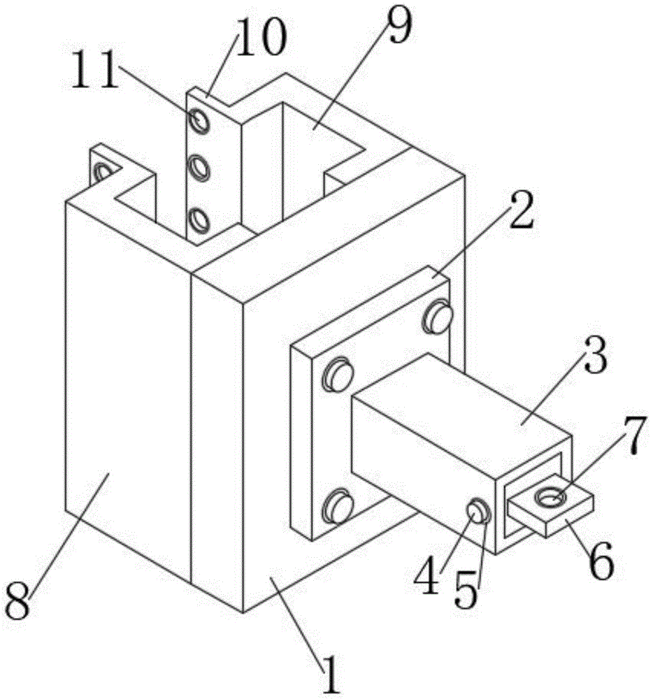
图1为本实用新型提出的一种视频监控设备的安装维护装置的整体结构图;Fig. 1 is the overall structure diagram of the installation and maintenance device of a kind of video surveillance equipment proposed by the utility model;
图2为图1中套杆的展开结构示意图;Fig. 2 is the unfolded structure schematic diagram of the sleeve rod in Fig. 1;
图3为图2中移动块的整体结构示意图。FIG. 3 is a schematic diagram of the overall structure of the moving block in FIG. 2 .
图中:1、装置主体;2、固定板;3、套杆;4、螺杆;5、固定环;6、支撑板;7、定位螺孔;8、夹板;9、固定卡扣;10、连接板; 11、连接螺孔;12、支杆;13、移动块;14、滑槽;15、定位杆。In the figure: 1. Main body of the device; 2. Fixing plate; 3. Sleeve rod; 4. Screw; 5. Fixing ring; 6. Support plate; 7. Positioning screw hole; 8. Plywood; Connecting plate; 11. Connecting screw hole; 12. Support rod; 13. Moving block; 14. Chute; 15. Positioning rod.
具体实施方式Detailed ways
下面将结合本实用新型实施例中的附图,对本实用新型实施例中的技术方案进行清楚、完整地描述,显然,所描述的实施例仅仅是本实用新型一部分实施例,而不是全部的实施例。The technical solutions in the embodiments of the present utility model will be clearly and completely described below with reference to the accompanying drawings in the embodiments of the present utility model. Obviously, the described embodiments are only a part of the embodiments of the present utility model, rather than all the implementations. example.
参照图1-3,一种视频监控设备的安装维护装置,包括装置主体 1,装置主体1的背部设有定位杆15,且定位杆15与装置主体1固定连接,装置主体1的一侧设有移动块13,设备内部组件使用时通过外部控制器进行控制。1-3, an installation and maintenance device for video surveillance equipment includes a device
装置主体1的背部设有定位杆15,且定位杆15与装置主体1固定连接,装置主体1的一侧设有移动块13,且移动块13的表面设有滑槽14,且定位杆15通过贯穿滑槽14的方式与滑槽14活动连接,移动块13的一侧设有夹板8,且夹板8与移动块13固定连接,夹板 8的内侧设有固定卡扣9,且夹板8平行等距的分布在装置主体1的背部,夹板8的外侧设有连接板10,且连接板10的表面设有连接螺孔11,连接板10之间呈平行对立分布,且连接板10与夹板8固定连接。The back of the device
当装置在安装时,由于滑槽14与定位杆15之间为活动连接,使用者可以通过向两侧拉动移动块13,使移动块13可以在外力的拉动下顺着滑槽14在装置主体1的背部移动,从而使夹板8之间的间距可以在移动块13的带动下被拉开,随后使用者可以将夹板8内侧的固定卡扣9贴合固定在柱体的表面,并通过外部连接杆贯穿连接螺孔11,使连接板10之间呈连接状态,随后移动块13会因连接板10之间的固定而停止自身的移动,从而使装置可以更加便捷的调节自身的间距,提高了装置的泛用性。When the device is being installed, since the
装置主体1的表面设有固定板2,且固定板2与装置主体1固定连接,固定板2的表面上设有套杆3,且套杆3的内侧设有支杆12,并且支杆12与套杆3活动连接,套杆3与支杆12的表面均设有固定环5,且套杆3的外侧设有螺杆4,螺杆4通过贯穿固定环5内部的方式使套杆3与支杆12固定连接,支杆12的外侧设有支撑板6,且支撑板6的表面设有定位螺孔7。The surface of the device
当装置在使用时,使用者可以使用外部零件来将摄像头固定在支撑板6表面的定位螺孔7内,随后使用者可以将螺杆4从套杆3的外侧取下,使支杆12可以从套杆3的内部拉伸到外界,随后当支杆12 拉伸至指定长度时,使用者可以再次将螺杆4贯穿于套杆3与支杆12表面的固定环5内,使支杆12可以固定在套杆3的内侧,从而使固定在支撑板6表面的摄像头可以通过拉伸支杆12的方式来调节自身与装置主体1的间距,增加了摄像头的摄像角度。When the device is in use, the user can use external parts to fix the camera in the
工作原理:本实用新型中,设备使用之前使用者需检查装置各部件之间的紧密性,随后当装置在安装时,由于滑槽14与定位杆15之间为活动连接,使用者可以通过向两侧拉动移动块13,使移动块13 可以在外力的拉动下顺着滑槽14在装置主体1的背部移动,从而使夹板8之间的间距可以在移动块13的带动下被拉开,随后使用者可以将夹板8内侧的固定卡扣9贴合固定在柱体的表面,并通过外部连接杆贯穿连接螺孔11,使连接板10之间呈连接状态,随后移动块13 会因连接板10之间的固定而停止自身的移动,从而使装置可以更加便捷的调节自身的间距,提高了装置的泛用性;Working principle: In this utility model, the user needs to check the tightness between the various parts of the device before the device is used, and then when the device is installed, since the
当装置在使用时,使用者可以使用外部零件来将摄像头固定在支撑板6表面的定位螺孔7内,随后使用者可以将螺杆4从套杆3的外侧取下,使支杆12可以从套杆3的内部拉伸到外界,随后当支杆12 拉伸至指定长度时,使用者可以再次将螺杆4贯穿于套杆3与支杆12表面的固定环5内,使支杆12可以固定在套杆3的内侧,从而使固定在支撑板6表面的摄像头可以通过拉伸支杆12的方式来调节自身与装置主体1的间距,增加了摄像头的摄像角度;When the device is in use, the user can use external parts to fix the camera in the
上述实施例为本实用新型较佳的实施方式,但本实用新型的实施方式并不受上述实施例的限制,其他的任何未背离本实用新型的精神实质与原理下所作的改变、修饰、替代、组合、简化,均应为等效的置换方式,都包含在本实用新型的保护范围之内。The above-mentioned embodiments are preferred embodiments of the present utility model, but the embodiments of the present utility model are not limited by the above-mentioned embodiments, and any other changes, modifications, and substitutions made without departing from the spirit and principle of the present utility model , combination and simplification, all should be equivalent replacement methods, which are all included in the protection scope of the present invention.
在本实用新型的描述中,需要理解的是术语“上”、“下”、“前”、“后”、“左”、“右”、“竖直”、“水平”、“顶”、“底”、“内”、“外”等指示方位或位置关系的术语为基于附图所示的方位或位置关系,仅是为了便于描述本实用新型和简化描述,而不是指示或暗示所指的设备或元件必须具有特定的方位、以特定的方位构造和操作,因此不能理解为对本实用新型的限制。In the description of the present invention, it should be understood that the terms "upper", "lower", "front", "rear", "left", "right", "vertical", "horizontal", "top", Terms indicating orientation or positional relationship such as "bottom", "inner" and "outer" are based on the orientation or positional relationship shown in the accompanying drawings, and are only for the convenience of describing the present invention and simplifying the description, rather than indicating or implying that The device or element must have a specific orientation, be constructed and operated in a specific orientation, and therefore should not be construed as a limitation of the present invention.
在本说明书的描述中,若出现术语“一个实施例”、“一些实施例”、“具体实施例”等的描述意指结合该实施例或示例描述的具体特征、结构、材料或特点包含于本实用新型的至少一个实施例或示例中。在本说明书中,对上述术语的示意性表述不一定指的是相同的实施例或实例。而且,描述的具体特征、结构、材料或特点可以在任何的一个或多个实施例或示例中以合适的方式结合。In the description of this specification, where the terms "one embodiment," "some embodiments," "specific embodiments," etc. appear in the description, it means that the specific features, structures, materials, or characteristics described in connection with the embodiment or example are contained in in at least one embodiment or example of the present invention. In this specification, schematic representations of the above terms do not necessarily refer to the same embodiment or instance. Furthermore, the particular features, structures, materials or characteristics described may be combined in any suitable manner in any one or more embodiments or examples.
以上公开的本实用新型优选实施例只是用于帮助阐述本实用新型。优选实施例并没有详尽叙述所有的细节,也不限制该实用新型仅为的具体实施方式。本实用新型不受上述实施例的限制,上述实施例和说明书中描述的只是本实用新型的原理,在不脱离本实用新型精神和范围的前提下本实用新型还会有各种变化和改进,这些变化和改进都落入要求保护的本实用新型的范围内。本说明书选取并具体描述这些实施例,是为了更好地解释本实用新型的原理和实际应用,从而使所属技术领域技术人员能很好地理解和利用本实用新型。本实用新型仅受权利要求书及其全部范围和等效物的限制。The preferred embodiments of the present invention disclosed above are only used to help illustrate the present invention. The preferred embodiments do not exhaustively describe all the details, nor do they limit the invention to specific embodiments only. The present utility model is not limited by the above-mentioned embodiments. The above-mentioned embodiments and descriptions are only the principles of the present utility model. The present utility model will have various changes and improvements without departing from the spirit and scope of the present utility model. Such changes and improvements fall within the scope of the claimed invention. This specification selects and specifically describes these embodiments in order to better explain the principle and practical application of the present invention, so that those skilled in the art can well understand and utilize the present invention. The present invention is limited only by the claims and their full scope and equivalents.
Claims (6)
Priority Applications (1)
| Application Number | Priority Date | Filing Date | Title |
|---|---|---|---|
| CN202220344120.3U CN217208826U (en) | 2022-02-21 | 2022-02-21 | Installation and maintenance device of video monitoring equipment |
Applications Claiming Priority (1)
| Application Number | Priority Date | Filing Date | Title |
|---|---|---|---|
| CN202220344120.3U CN217208826U (en) | 2022-02-21 | 2022-02-21 | Installation and maintenance device of video monitoring equipment |
Publications (1)
| Publication Number | Publication Date |
|---|---|
| CN217208826U true CN217208826U (en) | 2022-08-16 |
Family
ID=82798014
Family Applications (1)
| Application Number | Title | Priority Date | Filing Date |
|---|---|---|---|
| CN202220344120.3U Expired - Fee Related CN217208826U (en) | 2022-02-21 | 2022-02-21 | Installation and maintenance device of video monitoring equipment |
Country Status (1)
| Country | Link |
|---|---|
| CN (1) | CN217208826U (en) |
-
2022
- 2022-02-21 CN CN202220344120.3U patent/CN217208826U/en not_active Expired - Fee Related
Similar Documents
| Publication | Publication Date | Title |
|---|---|---|
| CN211289313U (en) | Monitoring equipment that suitability is strong | |
| CN206181253U (en) | Detachable wireless long -distance formula video monitor | |
| CN216520818U (en) | Monitoring system mounting rack with self-adaptive angle adjustment function | |
| CN208025042U (en) | A kind of elevator monitoring apparatus being easily installed | |
| CN213880070U (en) | Security protection watch-dog based on face identification | |
| CN212367361U (en) | Monitoring equipment convenient to altitude mixture control | |
| CN210135396U (en) | Multi-angle automatic regulating apparatus for camera | |
| CN211083495U (en) | Dustproof supervisory equipment mounting bracket | |
| CN210680612U (en) | Vehicle-mounted monitoring camera device | |
| CN218565069U (en) | Supporting structure capable of automatically adjusting security monitoring | |
| CN112681563A (en) | Novel building wall | |
| CN110906141A (en) | Wall-mounted mounting structure of indoor monitoring equipment | |
| CN210270498U (en) | Medical image projection device | |
| CN210069344U (en) | Outdoor security protection safety supervision video monitoring equipment mounting bracket | |
| CN211663442U (en) | Unmanned aerial vehicle is patrolled and examined to electric power | |
| CN211146012U (en) | Movable monitoring equipment | |
| CN208652006U (en) | A kind of video equipment with multidirectional monitoring | |
| CN210291229U (en) | Easy-to-install surveillance cameras | |
| CN111056006A (en) | Unmanned aerial vehicle is patrolled and examined to electric power | |
| CN118328258B (en) | Fixed knot constructs and has this fixed knot to construct supervisory equipment | |
| CN211574707U (en) | Public security protection supervisory equipment | |
| CN211667444U (en) | Regulating device of monitoring equipment | |
| CN218153513U (en) | Adjustable security protection monitoring device | |
| CN214249048U (en) | But outer sunshade door and window is with angle regulation's real time monitoring equipment | |
| CN218626344U (en) | Building perimeter long cylinder type monitoring camera |
Legal Events
| Date | Code | Title | Description |
|---|---|---|---|
| GR01 | Patent grant | ||
| GR01 | Patent grant | ||
| TR01 | Transfer of patent right | ||
| TR01 | Transfer of patent right |
Effective date of registration: 20230509 Address after: 430000 Assistant Enterprise Business Secretary Service Co., Ltd. Settled in Wuhan, Hubei Province Trusteeship Number: 773 Patentee after: Wuhan Miaoyouyan Technology Co.,Ltd. Address before: 430000 room a-1703, 17th floor, unit a, Yinghua building, gongnongwan, Hongshan District, Wuhan City, Hubei Province Patentee before: Wuhan Baijin Technology Development Co.,Ltd. |
|
| CF01 | Termination of patent right due to non-payment of annual fee | ||
| CF01 | Termination of patent right due to non-payment of annual fee |
Granted publication date: 20220816 |