Anti-corrosion filter for desizing in fabric production
Technical Field
The utility model relates to a fabric production technical field specifically is a fabric production desizing is with anticorrosion filter.
Background
The fabric is a flat film block formed by crossing, winding and connecting fine flexible objects, the woven fabric is formed by yarns with a crossing relation, the knitted fabric is formed by yarns with a winding relation, the non-woven fabric is formed by yarns with a connecting relation, and the third fabric is formed by yarns with a crossing/winding relation; the fabric in the prior art needs to be filtered for use during production, the filtered fabric is difficult to collect and treat by the conventional filtering device, and the fabric is easy to block after being stacked for a long time and has poor use effect; meanwhile, the feed inlet of the filtering device is mostly open, dust is easily accumulated in the device after the device is not used for a long time, the later-stage filtering use is influenced, and the protection effect is poor.
SUMMERY OF THE UTILITY MODEL
Technical problem to be solved
The utility model provides a to prior art not enough, the utility model provides a fabric production desizing is with anti-corrosion filter has solved the problem that proposes in the above-mentioned background art.
The second technical proposal.
The utility model discloses a realize above-mentioned purpose and specifically adopt following technical scheme:
the utility model provides a fabric production desizing is with anti-corrosion filter, includes the box, four supporting legs are installed to the bottom of box, one side of box is equipped with the drain pipe, the upper end middle part of box is equipped with the feeder hopper, the upper end of box is equipped with protection component, the mounting panel is installed to one side of box, install the motor on the mounting panel, the output of motor is connected with the brush roller, the front end middle part of box rotates there is the C shaped plate, the swash plate is installed to the C shaped plate, be connected with coupling assembling jointly between C shaped plate and the box, the inner chamber mid-mounting of box has the material pouring otter board.
Further, coupling assembling is including installing the shape board that returns on C shaped plate one side upper portion, the one end mid-mounting of box has the fixed block, the activity has the movable rod on the fixed block, the limiting plate is installed on the top of movable rod, install the pull ring on the limiting plate, the inserted block is installed to the bottom of movable rod, the extrusion spring is installed to the upper end of inserted block, the extrusion spring is connected with the fixed block.
Further, the size of the insertion block is matched with the size of the inner cavity of the return-shaped plate.
Further, the protection component comprises two fixing plates which are symmetrically installed at the upper end of the box body, a sliding rod is connected between the fixing plates, two sliding blocks are arranged on the sliding rod in a sliding mode, two reset springs are installed on the fixing plates close to the near ends of the fixing plates respectively and are connected with the two sliding blocks respectively, two connecting blocks are installed on the sliding blocks respectively, two connecting plates are installed at the rear ends of the connecting blocks, two protection plates are installed at the ends, far away from the connecting blocks, of the connecting plates, handles are installed on the protection plates, two iron absorbing plates are installed at the ends, far away from each other, of the sliding blocks, and two iron blocks are installed on the fixing plates close to the near ends of the fixing plates.
Furthermore, the protection plate is tightly attached to the feed hopper, and the iron attracting plate and the iron block are attracted magnetically.
Furthermore, the C-shaped plate is rotatably connected with the box body through a hinge.
(III) advantageous effects
Compared with the prior art, the utility model provides a fabric production desizing is with anticorrosion filter possesses following beneficial effect:
the utility model discloses, through the setting of coupling assembling, be convenient for open the C shaped plate, the fabric after filtering through falling the material otter board thereupon landing to the C shaped plate inside, be convenient for collect it thereupon and take out the processing use, the filter effect is good, the setting of swash plate is convenient for be in the C shaped plate with the fabric size, simple structure has strengthened the result of use of device, the setting of brush roller is because its function of adhesion foreign matter is extremely strong, thereby has strengthened its filter effect; through the setting of protection component, strengthened the safeguard effect to the device, avoided present filter equipment to adopt the mode of the feed inlet of opening form, its inside dust that easily drops when the device does not use, therefore influence the problem of later stage filter effect, the safeguard effect is good, simple structure has strengthened the result of use of device.
Drawings
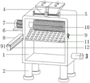
Fig. 1 is a schematic view of the overall structure of the present invention;
FIG. 2 is a schematic view of the internal structure of the case of the present invention;
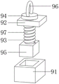
fig. 3 is an exploded view of the structure of the connection assembly of the present invention;
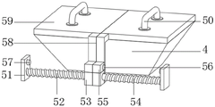
fig. 4 is a schematic structural diagram of the protection assembly of the present invention.
In the figure: 1. a box body; 2. supporting legs; 3. a drain pipe; 4. a feed hopper; 5. a guard assembly; 50. a handle; 51. a fixing plate; 52. a slide bar; 53. a slider; 54. a return spring; 55. connecting blocks; 56. an iron sucking plate; 57. an iron block; 58. a connecting plate; 59. a protection plate; 6. mounting a plate; 7. a motor; 8. a C-shaped plate; 9. a connecting assembly; 91. a return plate; 92. a fixed block; 93. a movable rod; 94. a limiting plate; 95. inserting a block; 96. a pull ring; 97. extruding the spring; 10. a brush roller; 11. pouring a screen plate; 12. a sloping plate.
Detailed Description
The technical solutions in the embodiments of the present invention will be described clearly and completely with reference to the accompanying drawings in the embodiments of the present invention, and it is obvious that the described embodiments are only some embodiments of the present invention, not all embodiments. Based on the embodiments in the present invention, all other embodiments obtained by a person skilled in the art without creative work belong to the protection scope of the present invention.
Examples
As shown in fig. 1, fig. 2, fig. 3 and fig. 4, an embodiment of the present invention provides an anti-corrosion filter for fabric production desizing, which includes a box 1, four support legs 2 are installed at the bottom end of the box 1, a drain pipe 3 is arranged at one side of the box 1, a feed hopper 4 is arranged at the middle part of the upper end of the box 1, a protective component 5 is arranged at the upper end of the box 1, a mounting plate 6 is installed at one side of the box 1, a motor 7 is installed on the mounting plate 6, an output end of the motor 7 is connected with a brush roller 10, a C-shaped plate 8 is rotated at the middle part of the front end of the box 1, an inclined plate 12 is installed in the C-shaped plate 8, a connecting component 9 is jointly connected between the C-shaped plate 8 and the box 1, and a material pouring screen plate 11 is installed at the middle part of an inner cavity of the box 1; when the device is used, the C-shaped plate 8 is convenient to open through the arrangement of the connecting assembly 9, the fabric filtered on the material pouring screen plate 11 slides into the C-shaped plate 8 along with the C-shaped plate, the fabric is convenient to collect, take out, treat and use, the filtering effect is good, the size of the fabric is convenient to be in the C-shaped plate 8 due to the arrangement of the inclined plate 12, the structure is simple, the using effect of the device is enhanced, and the arrangement of the brush roller 10 has the extremely strong function of adhering foreign matters, so that the filtering effect is enhanced; through the setting of protection component 5, strengthened the protecting effect to the device, avoided present filter equipment to adopt the mode of the feed inlet of opening form, its inside dust that easily drops when the device does not use, therefore influence the problem of later stage filter effect, the protecting effect is good, and simple structure has strengthened the result of use of device.
As shown in fig. 3, in some embodiments, the connecting assembly 9 includes a return plate 91 installed at the upper portion of one side of the C-shaped plate 8, a fixed block 92 is installed at the middle of one end of the box body 1, a movable rod 93 is movably installed on the fixed block 92, a limit plate 94 is installed at the top end of the movable rod 93, a pull ring 96 is installed on the limit plate 94, an insertion block 95 is installed at the bottom end of the movable rod 93, an extrusion spring 97 is installed at the upper end of the insertion block 95, and the extrusion spring 97 is connected with the fixed block 92; during the use, through pulling pull ring 96, along with extrusion spring 97 compression, drive the movable rod 93 and slide on, the inserted block 95 moves up, until breaking away from back shaped plate 91, rotates C shaped plate 8 this moment, to its inside fabric of storing collect can, simple structure, it is effectual to collect.
As shown in FIG. 3, in some embodiments, the size of the insert 95 matches the size of the interior cavity of the clip 91 to facilitate the use of a stop for the position of the C-shaped plate 8 to facilitate collection of the fabric.
As shown in fig. 4, in some embodiments, the protection assembly 5 includes two fixing plates 51 symmetrically installed at the upper end of the box body 1, a sliding rod 52 is connected between the two fixing plates 51, two sliding blocks 53 are slidably arranged on the sliding rod 52, return springs 54 are installed at the mutually close ends of the two fixing plates 51, the two return springs 54 are respectively connected with the two sliding blocks 53, connecting blocks 55 are installed on the two sliding blocks 53, connecting plates 58 are installed at the rear ends of the two connecting blocks 55, protection plates 59 are installed at the ends of the two connecting plates 58 far away from the connecting blocks 55, handles 50 are installed on the two protection plates 59, iron absorbing plates 56 are installed at the mutually far ends of the two sliding blocks 53, and iron blocks 57 are installed at the mutually close ends of the two fixing plates 51; during the use, through two handles 50 of reverse pulling, along with slider 53 slides on slide bar 52, reset spring 54 extrudees, want to be close to and attract until inhaling iron plate 56 and iron plate 57, along with it is spacing to two guard plate 59 positions, feed thereupon can, when not using, to relative direction pulling handle 50, two slider 53 keep away from behind two fixed plates 51, along with reset of reset spring 54, along with two guard plate 59 are close to each other and contact, the protection of having accomplished feeder hopper 4 this moment is airtight, use such as dustproof to device inside thereupon, the result of use of device has been strengthened.
As shown in fig. 4, in some embodiments, the protection plate 59 is tightly attached to the feeding hopper 4, and the iron attraction plate 56 and the iron block 57 are magnetically attracted to each other, so that the protection plate 59 is conveniently limited in position for use, and the magnetic iron-based feeding device is simple in structure and convenient to operate.
As shown in fig. 1, in some embodiments, the C-shaped plate 8 is rotatably connected to the box body 1 through a hinge, so that the fabric collected in the C-shaped plate 8 can be conveniently discharged, treated and used.
Finally, it should be noted that: although the present invention has been described in detail with reference to the foregoing embodiments, it will be apparent to those skilled in the art that modifications may be made to the embodiments described above, or equivalents may be substituted for elements thereof. Any modification, equivalent replacement, or improvement made within the spirit and principle of the present invention should be included in the protection scope of the present invention.