CN217173446U - High-efficient printing and dyeing wastewater advanced treatment device - Google Patents
High-efficient printing and dyeing wastewater advanced treatment device Download PDFInfo
- Publication number
- CN217173446U CN217173446U CN202220258449.8U CN202220258449U CN217173446U CN 217173446 U CN217173446 U CN 217173446U CN 202220258449 U CN202220258449 U CN 202220258449U CN 217173446 U CN217173446 U CN 217173446U
- Authority
- CN
- China
- Prior art keywords
- treatment
- chamber
- filter screen
- dyeing wastewater
- blocking net
- Prior art date
- Legal status (The legal status is an assumption and is not a legal conclusion. Google has not performed a legal analysis and makes no representation as to the accuracy of the status listed.)
- Active
Links
- 238000004043 dyeing Methods 0.000 title claims abstract description 20
- 239000002351 wastewater Substances 0.000 title claims abstract description 17
- XLYOFNOQVPJJNP-UHFFFAOYSA-N water Substances O XLYOFNOQVPJJNP-UHFFFAOYSA-N 0.000 claims abstract description 59
- 230000000903 blocking effect Effects 0.000 claims abstract description 43
- 239000002893 slag Substances 0.000 claims abstract description 34
- 238000005192 partition Methods 0.000 claims abstract description 18
- 238000004065 wastewater treatment Methods 0.000 claims abstract description 17
- 238000003756 stirring Methods 0.000 claims description 11
- 239000011148 porous material Substances 0.000 claims 1
- 239000003795 chemical substances by application Substances 0.000 abstract description 6
- 239000013049 sediment Substances 0.000 abstract description 6
- 238000000034 method Methods 0.000 description 5
- 239000012535 impurity Substances 0.000 description 2
- 244000025254 Cannabis sativa Species 0.000 description 1
- 235000012766 Cannabis sativa ssp. sativa var. sativa Nutrition 0.000 description 1
- 235000012765 Cannabis sativa ssp. sativa var. spontanea Nutrition 0.000 description 1
- 229920000742 Cotton Polymers 0.000 description 1
- 235000009120 camo Nutrition 0.000 description 1
- 235000005607 chanvre indien Nutrition 0.000 description 1
- 238000004140 cleaning Methods 0.000 description 1
- 238000010586 diagram Methods 0.000 description 1
- 230000000694 effects Effects 0.000 description 1
- 238000005516 engineering process Methods 0.000 description 1
- 239000000835 fiber Substances 0.000 description 1
- 239000011487 hemp Substances 0.000 description 1
- 239000010842 industrial wastewater Substances 0.000 description 1
- 239000010813 municipal solid waste Substances 0.000 description 1
- 239000005416 organic matter Substances 0.000 description 1
- 230000001376 precipitating effect Effects 0.000 description 1
- 239000010865 sewage Substances 0.000 description 1
- -1 silk Substances 0.000 description 1
- 238000004513 sizing Methods 0.000 description 1
- 239000000126 substance Substances 0.000 description 1
- 239000004094 surface-active agent Substances 0.000 description 1
- 210000002268 wool Anatomy 0.000 description 1
Images


Classifications
-
- Y—GENERAL TAGGING OF NEW TECHNOLOGICAL DEVELOPMENTS; GENERAL TAGGING OF CROSS-SECTIONAL TECHNOLOGIES SPANNING OVER SEVERAL SECTIONS OF THE IPC; TECHNICAL SUBJECTS COVERED BY FORMER USPC CROSS-REFERENCE ART COLLECTIONS [XRACs] AND DIGESTS
- Y02—TECHNOLOGIES OR APPLICATIONS FOR MITIGATION OR ADAPTATION AGAINST CLIMATE CHANGE
- Y02W—CLIMATE CHANGE MITIGATION TECHNOLOGIES RELATED TO WASTEWATER TREATMENT OR WASTE MANAGEMENT
- Y02W10/00—Technologies for wastewater treatment
- Y02W10/30—Wastewater or sewage treatment systems using renewable energies
- Y02W10/37—Wastewater or sewage treatment systems using renewable energies using solar energy
Landscapes
- Filtration Of Liquid (AREA)
Abstract
The utility model relates to a waste water treatment device field especially relates to a high-efficient printing and dyeing wastewater advanced treatment unit. The device comprises a treatment box, a partition plate, a slag blocking net and a treatment assembly; a water inlet pipe and a water outlet pipe are respectively arranged on two sides of the treatment box; the baffle plates are arranged at two ends of the treatment box and divide the treatment box into a water inlet chamber, a treatment chamber and a water outlet chamber; the slag blocking net is arranged on the partition plate, so that the water inlet chamber, the treatment chamber and the water outlet chamber are communicated in sequence; the processing assembly is disposed on the processing chamber. The utility model discloses setting up and settling agent, blocking sediment net, filter screen and filter core cooperation, adopting multiple processing mode, purify repeatedly, comprehensive, high-efficient to waste water treatment. After a period of treatment, the mounting frame is taken out, the filter screen and the filter element are cleaned and replaced, and the high efficiency and the stability of the treatment are ensured. Set up mediation water conservancy diversion spare, clean, the mediation to blocking sediment net and filter screen, guide rivers direction, further improve waste water treatment's efficiency.
Description
Technical Field
The utility model relates to a waste water treatment device field especially relates to a high-efficient printing and dyeing wastewater advanced treatment unit.
Background
The printing and dyeing wastewater is wastewater discharged in the processes of pretreatment, dyeing, printing, finishing and the like of cotton, wool, hemp, silk, chemical fiber or blended products, contains a large amount of complex components such as dye, sizing agent, surfactant and the like, has the characteristics of high chromaticity, high organic matter concentration, strong alkalinity, large water quality and water quantity change and the like, is difficult to treat, and belongs to industrial wastewater difficult to treat.
The existing printing and dyeing wastewater treatment device has the advantages of single treatment mode, untimely replacement and cleaning of a filter screen and a filter element, easy unsmooth treatment process and low treatment efficiency.
SUMMERY OF THE UTILITY MODEL
Aiming at the problems in the background technology, a high-efficiency advanced treatment device for printing and dyeing wastewater is provided. The utility model discloses setting up and settling agent, blocking sediment net, filter screen and filter core cooperation, adopting multiple processing mode, purify repeatedly, comprehensive, high-efficient to waste water treatment. After a period of treatment, the mounting frame is taken out, the filter screen and the filter element are cleaned and replaced, and the high efficiency and the stability of the treatment are ensured. Set up mediation water conservancy diversion spare, clean, the mediation to blocking sediment net and filter screen, guide rivers direction, further improve waste water treatment's efficiency.
The utility model provides a high-efficiency advanced treatment device for printing and dyeing wastewater, which comprises a treatment box, a partition plate, a slag blocking net and a treatment component; a water inlet pipe and a water outlet pipe are respectively arranged on two sides of the treatment box; the baffle plates are arranged at two ends of the treatment box and divide the treatment box into a water inlet chamber, a treatment chamber and a water outlet chamber; the slag blocking net is arranged on the partition plate, so that the water inlet chamber, the treatment chamber and the water outlet chamber are communicated in sequence; the processing assembly is disposed on the processing chamber.
The treatment component comprises a mounting frame, a mounting plate, a filter screen and a filter element; the upper end of the processing chamber is opened; the mounting rack is detachably arranged on the opening; the mounting plates are arranged on two sides of the bottom of the mounting frame, are parallel to the partition plate and are connected with the inner wall of the processing chamber in a sliding manner; the filter screen is arranged on the mounting plate and communicated with the slag blocking screen; the filter core sets up between two sets of mounting panels, communicates the filter screen.
Preferably, the mounting bracket is n type structure, covers the opening, and the block setting is on handling the case, and with handle the case and pass through the staple and be connected.
Preferably, the aperture of the slag blocking net close to the water inlet is larger than that of the slag blocking net close to the water outlet.
Preferably, a feeding hopper is arranged on the treatment box; the feeding hopper is communicated with the water inlet chamber.
Preferably, the treatment tank is provided with a dredging flow guide part; the dredging and flow guiding parts are arranged in two groups and are respectively positioned on two sides of the processing assembly.
Preferably, the dredging and flow guiding part comprises a motor, a rotating shaft, a stirring frame and a dredging brush; the motor is arranged on the processing box; one end of the rotating shaft is connected with a main shaft of the motor, and the other end of the rotating shaft rotatably penetrates through the slag blocking net and faces the filter screen on the same side; two groups of stirring frames are arranged on the rotating shaft and are respectively positioned on one side of the slag blocking net and one side of the filter screen; the dredging brush is arranged on the stirring frame and is in sliding contact with the corresponding slag blocking net/filter screen.
Preferably, the dredging and flow guiding piece is provided with a flow guiding paddle.
Preferably, the guide paddles of the two groups of dredging guide parts are obliquely arranged, and the guide directions are consistent.
Compared with the prior art, the utility model discloses following profitable technological effect has:
the utility model discloses setting up and settling agent, blocking sediment net, filter screen and filter core cooperation, adopting multiple processing mode, purify repeatedly, comprehensive, high-efficient to waste water treatment. After a period of treatment, the mounting frame is taken out, the filter screen and the filter element are cleaned and replaced, and the high efficiency and the stability of the treatment are ensured. Set up mediation water conservancy diversion spare, clean, the mediation to blocking sediment net and filter screen, guide rivers direction, further improve waste water treatment's efficiency.
Drawings
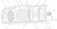
Fig. 1 is a schematic view of a first perspective structure according to an embodiment of the present invention;
FIG. 2 is a cross-sectional view of FIG. 1;
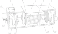
fig. 3 is a schematic diagram of a second perspective structure according to an embodiment of the present invention;
fig. 4 is a cross-sectional view of fig. 3.
Reference numerals: 1. a treatment box; 2. fixing nails; 3. a partition plate; 4. a slag blocking net; 5. a feeding hopper; 6. a mounting frame; 7. mounting a plate; 8. a filter screen; 9. a filter element; 10. a motor; 11. a rotating shaft; 12. a stirring frame; 13. a dredging brush; 14. a flow guiding paddle; 15. a water inlet pipe; 16. a water outlet pipe; 17. a water inlet chamber; 18. a processing chamber; 19. a water outlet chamber.
Detailed Description
Example one
As shown in figures 1-4, the utility model provides a high-efficiency advanced treatment device for printing and dyeing wastewater, which comprises a treatment box 1, a partition plate 3, a slag blocking net 4 and a treatment component; a water inlet pipe 15 and a water outlet pipe 16 are respectively arranged at two sides of the treatment box 1; the baffle plates 3 are arranged at two ends of the treatment box 1 and divide the treatment box into a water inlet chamber 17, a treatment chamber 18 and a water outlet chamber 19; the slag blocking net 4 is arranged on the partition board 3, so that the water inlet chamber 17, the treatment chamber 18 and the water outlet chamber 19 are communicated in sequence; the processing assembly is disposed on the process chamber 18.
The treatment assembly comprises a mounting frame 6, a mounting plate 7, a filter screen 8 and a filter element 9; the upper end of the processing chamber 18 is opened; the mounting frame 6 is detachably arranged on the opening; the mounting plates 7 are arranged on two sides of the bottom of the mounting frame 6, are parallel to the partition plate 3 and are connected with the inner wall of the processing chamber 18 in a sliding mode; the filter screen 8 is arranged on the mounting plate 7 and communicated with the slag blocking net 4; the filter element 9 is arranged between the two groups of mounting plates 7 and is communicated with the filter screen 8.
The working principle of the embodiment is as follows: the wastewater enters the water inlet chamber 17 and is mixed with the settling agent, and the impurity is intercepted by the slag blocking net 4. Then the wastewater enters a treatment chamber 18 and passes through a filter screen 8 at one side, a filter element 9 and a filter screen 8 at the other side in sequence for advanced treatment. And finally, the sewage enters a water outlet chamber 19, and impurities are intercepted again by the slag blocking net 4, so that the treatment is finished. Adopts various treatment modes, purifies repeatedly, and treats the wastewater comprehensively and efficiently. After a period of treatment, the mounting frame 6 is taken out, the filter screen 8 and the filter element 9 are cleaned and replaced, and the high efficiency and the stability of the treatment are ensured.
Example two
As shown in figures 1-4, the utility model provides a high-efficiency advanced treatment device for printing and dyeing wastewater, which comprises a treatment box 1, a partition plate 3, a slag blocking net 4 and a treatment component; a water inlet pipe 15 and a water outlet pipe 16 are respectively arranged at two sides of the treatment box 1; the baffle plates 3 are arranged at two ends of the treatment box 1 and divide the treatment box into a water inlet chamber 17, a treatment chamber 18 and a water outlet chamber 19; the slag blocking net 4 is arranged on the partition board 3, so that the water inlet chamber 17, the treatment chamber 18 and the water outlet chamber 19 are communicated in sequence; the processing assembly is disposed on the process chamber 18.
Furthermore, the aperture of the slag blocking net 4 close to the water inlet is larger than that of the slag blocking net 4 close to the water outlet. The wastewater is filtered step by step.
Further, a feeding hopper 5 is arranged on the treatment box 1; the feeding hopper 5 is communicated with an inlet chamber 17. The precipitating agent is conveniently and directly added.
The treatment assembly comprises a mounting frame 6, a mounting plate 7, a filter screen 8 and a filter element 9; the upper end of the processing chamber 18 is opened; the mounting frame 6 is detachably arranged on the opening; the mounting plates 7 are arranged on two sides of the bottom of the mounting frame 6, are parallel to the partition plate 3 and are connected with the inner wall of the processing chamber 18 in a sliding mode; the filter screen 8 is arranged on the mounting plate 7 and communicated with the slag blocking net 4; the filter element 9 is arranged between the two groups of mounting plates 7 and is communicated with the filter screen 8.
Further, mounting bracket 6 is n type structure, covers the opening, and the block setting is on handling case 1, and with handle case 1 and pass through staple 2 and be connected. The mounting frame 6 is convenient to mount and dismount.
EXAMPLE III
As shown in figures 1-4, the utility model provides a high-efficiency advanced treatment device for printing and dyeing wastewater, which comprises a treatment box 1, a partition plate 3, a slag blocking net 4 and a treatment component; a water inlet pipe 15 and a water outlet pipe 16 are respectively arranged at two sides of the treatment box 1; the baffle plates 3 are arranged at two ends of the treatment box 1 and divide the treatment box into a water inlet chamber 17, a treatment chamber 18 and a water outlet chamber 19; the slag blocking net 4 is arranged on the partition board 3, so that the water inlet chamber 17, the treatment chamber 18 and the water outlet chamber 19 are communicated in sequence; the processing assembly is disposed on the process chamber 18.
Furthermore, the aperture of the slag blocking net 4 close to the water inlet is larger than that of the slag blocking net 4 close to the water outlet.
Further, a feeding hopper 5 is arranged on the treatment box 1; the feeding hopper 5 is communicated with the water inlet chamber 17.
The treatment assembly comprises a mounting frame 6, a mounting plate 7, a filter screen 8 and a filter element 9; the upper end of the processing chamber 18 is opened; the mounting frame 6 is detachably arranged on the opening; the mounting plates 7 are arranged on two sides of the bottom of the mounting frame 6, are parallel to the partition plate 3 and are connected with the inner wall of the processing chamber 18 in a sliding mode; the filter screen 8 is arranged on the mounting plate 7 and communicated with the slag blocking net 4; the filter element 9 is arranged between the two groups of mounting plates 7 and is communicated with the filter screen 8.
Further, mounting bracket 6 is n type structure, covers the opening, and the block setting is on handling case 1, and with handle case 1 and pass through staple 2 and be connected.
Further, a dredging and flow guiding piece is arranged on the treatment box 1; the dredging and flow guiding parts are arranged in two groups and are respectively positioned on two sides of the processing assembly. The dredging and flow guiding part comprises a motor 10, a rotating shaft 11, a stirring frame 12 and a dredging brush 13; the motor 10 is arranged on the processing box 1; one end of the rotating shaft 11 is connected with a main shaft of the motor 10, and the other end of the rotating shaft rotates to penetrate through the slag blocking net 4 and faces the filter screen 8 on the same side; two groups of stirring frames 12 are arranged on the rotating shaft 11 and are respectively positioned at one side of the slag blocking net 4 and one side of the filter screen 8; the dredging brush 13 is arranged on the stirring frame 12 and is in sliding contact with the corresponding slag blocking net 4/filter screen 8.
Furthermore, a flow guiding paddle 14 is arranged on the dredging flow guiding piece.
Furthermore, the flow guiding paddles 14 of the two groups of dredging flow guiding parts are obliquely arranged, and the flow guiding directions are consistent.
This embodiment sets up mediation water conservancy diversion spare, drives stirring frame 12 and mediation brush 13 through motor 10 and rotates, mixes waste water, precipitant, cleans, the mediation to trash rack 4 and filter screen 8 simultaneously, and diversion oar 14 guides the rivers direction, further improves waste water treatment's efficiency.
The embodiments of the present invention have been described in detail with reference to the accompanying drawings, but the present invention is not limited thereto, and various changes can be made without departing from the gist of the present invention within the scope of knowledge possessed by those skilled in the art.
Claims (8)
1. The efficient advanced treatment device for the printing and dyeing wastewater is characterized by comprising a treatment box (1), a partition plate (3), a residue blocking net (4) and a treatment assembly; a water inlet pipe (15) and a water outlet pipe (16) are respectively arranged on two sides of the treatment box (1); the clapboards (3) are arranged at two ends of the treatment box (1) and divide the treatment box into a water inlet chamber (17), a treatment chamber (18) and a water outlet chamber (19); the slag blocking net (4) is arranged on the partition board (3) so that the water inlet chamber (17), the treatment chamber (18) and the water outlet chamber (19) are communicated in sequence; the processing assembly is arranged on the processing chamber (18);
the treatment component comprises a mounting rack (6), a mounting plate (7), a filter screen (8) and a filter element (9); the upper end of the processing chamber (18) is opened; the mounting rack (6) is detachably arranged on the opening; the mounting plates (7) are arranged on two sides of the bottom of the mounting frame (6), are parallel to the partition plate (3) and are connected with the inner wall of the processing chamber (18) in a sliding manner; the filter screen (8) is arranged on the mounting plate (7) and communicated with the slag blocking screen (4); the filter element (9) is arranged between the two groups of mounting plates (7) and is communicated with the filter screen (8).
2. The efficient advanced printing and dyeing wastewater treatment device as claimed in claim 1, characterized in that the mounting frame (6) is of an n-shaped structure, covers the opening, is arranged on the treatment box (1) in a clamping manner, and is connected with the treatment box (1) through fixing nails (2).
3. The efficient advanced printing and dyeing wastewater treatment device as claimed in claim 1, characterized in that the pore size of the residue blocking net (4) close to the water inlet is larger than that of the residue blocking net (4) close to the water outlet.
4. The efficient advanced printing and dyeing wastewater treatment device as claimed in claim 1, characterized in that a feeding hopper (5) is arranged on the treatment tank (1); the feeding hopper (5) is communicated with the water inlet chamber (17).
5. The efficient advanced printing and dyeing wastewater treatment device as claimed in claim 1, characterized in that a dredging diversion member is arranged on the treatment tank (1); the dredging and flow guiding parts are arranged in two groups and are respectively positioned on two sides of the processing assembly.
6. The efficient advanced printing and dyeing wastewater treatment device as claimed in claim 5, wherein the dredging diversion member comprises a motor (10), a rotating shaft (11), a stirring frame (12) and a dredging brush (13); the motor (10) is arranged on the processing box (1); one end of the rotating shaft (11) is connected with a main shaft of the motor (10), and the other end of the rotating shaft rotates to penetrate through the slag blocking net (4) and faces towards the filter screen (8) on the same side; two groups of stirring frames (12) are arranged on the rotating shaft (11) and are respectively positioned at one side of the slag blocking net (4) and one side of the filter screen (8); the dredging brush (13) is arranged on the stirring frame (12) and is in sliding contact with the corresponding slag blocking net (4)/the filter screen (8).
7. The efficient advanced printing and dyeing wastewater treatment device as claimed in claim 6, wherein the dredging diversion member is provided with diversion paddles (14).
8. The efficient advanced printing and dyeing wastewater treatment device as claimed in claim 7, wherein the diversion paddles (14) of the two sets of dredging diversion members are obliquely arranged, and the diversion directions are consistent.
Priority Applications (1)
| Application Number | Priority Date | Filing Date | Title |
|---|---|---|---|
| CN202220258449.8U CN217173446U (en) | 2022-02-09 | 2022-02-09 | High-efficient printing and dyeing wastewater advanced treatment device |
Applications Claiming Priority (1)
| Application Number | Priority Date | Filing Date | Title |
|---|---|---|---|
| CN202220258449.8U CN217173446U (en) | 2022-02-09 | 2022-02-09 | High-efficient printing and dyeing wastewater advanced treatment device |
Publications (1)
| Publication Number | Publication Date |
|---|---|
| CN217173446U true CN217173446U (en) | 2022-08-12 |
Family
ID=82737656
Family Applications (1)
| Application Number | Title | Priority Date | Filing Date |
|---|---|---|---|
| CN202220258449.8U Active CN217173446U (en) | 2022-02-09 | 2022-02-09 | High-efficient printing and dyeing wastewater advanced treatment device |
Country Status (1)
| Country | Link |
|---|---|
| CN (1) | CN217173446U (en) |
Cited By (1)
| Publication number | Priority date | Publication date | Assignee | Title |
|---|---|---|---|---|
| CN118458878A (en) * | 2024-07-10 | 2024-08-09 | 山西新辉活性炭有限公司 | Device and method for treating active carbon in coking wastewater |
-
2022
- 2022-02-09 CN CN202220258449.8U patent/CN217173446U/en active Active
Cited By (1)
| Publication number | Priority date | Publication date | Assignee | Title |
|---|---|---|---|---|
| CN118458878A (en) * | 2024-07-10 | 2024-08-09 | 山西新辉活性炭有限公司 | Device and method for treating active carbon in coking wastewater |
Similar Documents
| Publication | Publication Date | Title |
|---|---|---|
| CN208327573U (en) | A kind of municipal wastewater processing dedicated unit | |
| CN221821922U (en) | Municipal sewage treatment equipment | |
| CN210206159U (en) | Wastewater pretreatment device of multi-cylinder fourdrinier paper machine | |
| CN214087990U (en) | Waste water treatment device based on papermaking processing usefulness | |
| CN211688702U (en) | Domestic sewage treatment device | |
| CN109851082A (en) | A kind of application method of the waste water purification device of textile printing and dyeing | |
| CN211419781U (en) | Integrated device suitable for industrial sewage treatment | |
| CN222082545U (en) | Chemical waste liquid classification recovery processing device | |
| CN210505855U (en) | Towards version hydrologic cycle filter equipment | |
| CN219929653U (en) | Purification treatment device for sewage discharge of chemical fiber grey cloth fabric textile equipment | |
| CN217780926U (en) | Domestic sewage treatment device | |
| CN216890441U (en) | High-efficient purifier is used to industrial waste liquid | |
| CN216726181U (en) | Waste liquid treatment device for papermaking | |
| CN216005474U (en) | Sewage treatment mechanism for treating wastewater on metal surface | |
| CN114733831A (en) | High-efficient washing device system of quartz sand | |
| CN222024216U (en) | A filtering device for denitrification of domestic sewage | |
| CN223112501U (en) | Wastewater pretreatment device of desizing, boiling and bleaching combined machine | |
| CN220642849U (en) | MBR integrated sewage treatment equipment with denitrification and dephosphorization functions | |
| CN215479955U (en) | High-efficient industrial waste water purifier of environment-friendly | |
| CN212833208U (en) | Beer industry effluent filter equipment | |
| CN215516919U (en) | Papermaking wastewater treatment equipment | |
| CN210711028U (en) | Novel sewage treatment device | |
| CN218025677U (en) | Desulfurizing tower hydrologic cycle clarification plant | |
| CN214167384U (en) | Printing and dyeing wastewater treatment device | |
| CN215480267U (en) | Sewage precipitation filter equipment |
Legal Events
| Date | Code | Title | Description |
|---|---|---|---|
| GR01 | Patent grant | ||
| GR01 | Patent grant |