CN217167456U - Hinge type clamping machining center tool - Google Patents
Hinge type clamping machining center tool Download PDFInfo
- Publication number
- CN217167456U CN217167456U CN202121291412.7U CN202121291412U CN217167456U CN 217167456 U CN217167456 U CN 217167456U CN 202121291412 U CN202121291412 U CN 202121291412U CN 217167456 U CN217167456 U CN 217167456U
- Authority
- CN
- China
- Prior art keywords
- hinge
- plate
- oil cylinder
- workpiece
- axis
- Prior art date
- Legal status (The legal status is an assumption and is not a legal conclusion. Google has not performed a legal analysis and makes no representation as to the accuracy of the status listed.)
- Active
Links
- 230000007246 mechanism Effects 0.000 claims abstract description 86
- 238000003825 pressing Methods 0.000 claims abstract description 84
- 230000007704 transition Effects 0.000 claims abstract description 37
- 238000000034 method Methods 0.000 abstract description 4
- 238000003754 machining Methods 0.000 description 4
- 238000005520 cutting process Methods 0.000 description 2
- 238000010586 diagram Methods 0.000 description 2
- 230000000712 assembly Effects 0.000 description 1
- 238000000429 assembly Methods 0.000 description 1
- 230000000694 effects Effects 0.000 description 1
- 238000004519 manufacturing process Methods 0.000 description 1
- 230000002093 peripheral effect Effects 0.000 description 1
- 238000002360 preparation method Methods 0.000 description 1
Images



Classifications
-
- Y—GENERAL TAGGING OF NEW TECHNOLOGICAL DEVELOPMENTS; GENERAL TAGGING OF CROSS-SECTIONAL TECHNOLOGIES SPANNING OVER SEVERAL SECTIONS OF THE IPC; TECHNICAL SUBJECTS COVERED BY FORMER USPC CROSS-REFERENCE ART COLLECTIONS [XRACs] AND DIGESTS
- Y02—TECHNOLOGIES OR APPLICATIONS FOR MITIGATION OR ADAPTATION AGAINST CLIMATE CHANGE
- Y02P—CLIMATE CHANGE MITIGATION TECHNOLOGIES IN THE PRODUCTION OR PROCESSING OF GOODS
- Y02P90/00—Enabling technologies with a potential contribution to greenhouse gas [GHG] emissions mitigation
- Y02P90/02—Total factory control, e.g. smart factories, flexible manufacturing systems [FMS] or integrated manufacturing systems [IMS]
Landscapes
- Jigs For Machine Tools (AREA)
Abstract
The utility model relates to a machining center frock field discloses hinge type clamping machining center frock, including four-axis rotary mechanism and hinge pushing and pressing mechanism, the last hinge pushing and pressing mechanism that is equipped with of four-axis rotary mechanism, its characterized in that: the four-axis rotating mechanism comprises a bridge plate, the hinge pushing and pressing mechanism comprises a first oil cylinder, a pull rod, a connecting plate, a transition hinge, a hinge pressing block and a guide inclined block, the first oil cylinder is arranged on the bridge plate, the first oil cylinder is provided with the pull rod and drives the pull rod to move, the pull rod is hinged with the connecting plate, the connecting plate is hinged with the transition hinge, the transition hinge is hinged with the hinge pressing block, and the transition hinge is in sliding connection with a sliding groove in the guide inclined block. The utility model discloses a hinge pushing and pressing mechanism, hinge clamping mechanism, rotatory hydro-cylinder clamping mechanism and four-axis rotary mechanism combine together, only need two work pieces of clamping to process simultaneously to accomplish three face processing, the quality is easily guaranteed, and stability is good, this frock general strong, four alone operatable lathes, and the labour cost is original 1/2.
Description
Technical Field
The utility model relates to a machining center frock field has especially related to hinge type clamping machining center frock.
Background
Machining center is the multi-functional digit control machine tool of a high automation that has tool magazine and automatic tool changer, and application number CN 201610650287.1's utility model patent discloses a wheel hub machining center frock, and it includes: the clamp comprises a clamp body, a driving mechanism, a supporting mechanism, an angular positioning mechanism and a pressing mechanism. The driving mechanism is provided with a screw rod protruding out of the upper surface of the fixture body; the supporting mechanism is detachably connected to the upper surface of the fixture body and used for supporting a flange of a hub, and the supporting mechanism is arranged around the screw; the supporting mechanism comprises a supporting bottom plate and a plurality of supporting column assemblies which are detachably connected to the supporting bottom plate; the support column assembly comprises a top end support and at least one support column segment arranged below the top end support, the top end support is used for supporting a flange of a hub, and the height position of the top end support is adjustable; the angular positioning mechanism is arranged on the upper surface of the fixture body and positioned outside the supporting mechanism, the angular positioning mechanism is used for being connected with the outer peripheral edge of a flange of the hub to realize angular positioning of the hub, and the angular positioning mechanism is adjustable in height; the pressing mechanism is used for being matched with the position of a shaft shoulder of a bearing hole on the hub to press the hub; the pressing mechanism is sleeved on the screw rod, and the height position of the pressing mechanism on the screw rod is adjustable. The wheel hub machining center frock of above-mentioned patent is used for the wheel hub of centre gripping different models, and supporting mechanism, angular positioning mechanism are adjustable in the height to the wheel hub of cooperation different models has realized the universalization of wheel hub machining center frock, practices thrift the frock and places the place, has reduced frock cost of manufacture, reduces frock preparation cycle.
However, at present, when the traditional machining center machines automobile parts, a flat tongs is generally adopted to clamp and process a surface first, after the first surface is machined, the workpiece is disassembled, clamped and processed to process the second surface, and then the third surface is machined in sequence. Because the benchmark is not unified, and the clamping many times, the processing product quality stability is poor, machining efficiency is low, one person operates a lathe at most, and the cost of labor is high.
SUMMERY OF THE UTILITY MODEL
The utility model discloses shortcoming to among the prior art provides hinge type clamping machining center frock.
In order to solve the technical problem, the utility model discloses a following technical scheme can solve:
hinge type clamping machining center frock, including four-axis rotary mechanism and hinge pushing and pressing mechanism, four-axis rotary mechanism is equipped with hinge pushing and pressing mechanism, four-axis rotary mechanism includes the bridge plate, hinge pushing and pressing mechanism includes hydro-cylinder one, the pull rod, link the board, the transition hinge, the hinge briquetting, the direction sloping block, be equipped with hydro-cylinder one on the bridge plate, be equipped with the pull rod on the hydro-cylinder one and drive the pull rod and move, the pull rod is articulated with link the board, link the board and the hinge briquetting, the transition hinge is connected with the spout sliding connection on the direction sloping block, the hydro-cylinder drives the pull rod and moves down, the pull rod drives the transition hinge through link board and slides down along the spout on the direction sloping block, the transition hinge briquetting drives the hinge briquetting and moves down and right, hinge briquetting and work piece contact and the tight work piece of clamp. When the pull rod is pulled by the first oil cylinder, the connecting plate drives the transition hinge to slide downwards along the sliding groove in the guide inclined block, the hinge pressing block moves downwards and rightwards simultaneously, after the right end face of the hinge pressing block contacts with a workpiece, the hinge pressing block continues to move downwards until the lower end face of the hinge pressing block contacts with and clamps the workpiece, and meanwhile, the positioning screw I on the side face of the right end face clamps the workpiece.
Preferably, a first supporting seat is arranged on the bridge plate, a first positioning screw is arranged on the first supporting seat, and the first positioning screw is in contact with the workpiece and clamps the workpiece.
Preferably, a second supporting seat is arranged on the bridge plate, a second positioning screw is arranged on the second supporting seat, and the second positioning screw is in contact with the workpiece and clamps the workpiece. The first supporting seat is fixed on the bridge plate through a screw, the first positioning screw is fixed with the first supporting seat and the nut through threads, the positioning is in the length direction, and the positioning can be adjusted according to products with different lengths. The second supporting seat is fixed on the long groove of the bridge plate, multiple holes are formed in the long groove, the position of the second supporting seat is adjusted according to different product processing positions, the second positioning screw is connected with the second positioning seat through threads, and the second positioning screw is properly adjusted according to different widths of products.
Preferably, the hinge clamping mechanism comprises a second oil cylinder, a connecting bolt, a hinge joint, a fixed seat, a first pin shaft and a side pressing plate, the second oil cylinder is connected with the connecting bolt, the connecting bolt is connected with the hinge joint, one end of the side pressing plate is hinged with the hinge joint, and the side pressing plate is hinged with the fixed seat through the first pin shaft. When the second oil cylinder pushes the side pressing plate to move rightwards, the side pressing plate rotates around the first pin shaft, and the head of the side pressing plate clamps and tightly pushes a workpiece.
Preferably, the device further comprises a rotary oil cylinder clamping mechanism, wherein the rotary oil cylinder clamping mechanism comprises a rotary oil cylinder III and a pressing plate, and the pressing plate is arranged on the rotary oil cylinder III and drives the pressing plate to rotate. The third oil cylinder drives the pressing plate to open outwards or close inwards, so that the workpiece can be conveniently loaded and unloaded.
Preferably, the four-axis rotating mechanism further comprises a rotating four-axis, a four-axis tailstock and a four-axis L plate, wherein the four-axis L plate is arranged on the rotating four-axis and is connected with the four-axis tailstock through a bridge plate. The four-shaft rotating mechanism has the function of driving other mechanisms to rotate and brake together with the workpiece by 360 degrees, so that the multi-surface processing of the workpiece is ensured.
Preferably, the bridge plate is provided with an end face positioning support, and the workpiece is mounted on the end face positioning support.
The utility model discloses owing to adopted above technical scheme, have apparent technological effect: 1. one machine tool is changed into four machine tools, so that two labor costs are saved; 2. the hinge pushing and pressing mode is adopted for clamping, the side face can be clamped and the clamping in the height direction can be realized by one-time clamping, so that the power mechanism in one direction is reduced, the clamping is stable, and the efficiency is high. 3. The side face of the hinge clamping mechanism is clamped, and the cutting is stable in the machining process. 4. According to the adjustable positioning mechanism, various products can be clamped, and the universality is strong. 5. Two products can be clamped and processed at one time, and the efficiency is greatly improved; 6. the quality problem of the position tolerance of the workpiece is improved by 99.9 percent from the original 95 percent. The utility model discloses a hinge pushing and pressing mechanism, hinge clamping mechanism, rotatory hydro-cylinder clamping mechanism and four-axis rotary mechanism combine together, only need two work pieces of clamping to process simultaneously to accomplish three face processing, the quality is easily guaranteed, and stability is good, this frock general strong, four alone operatable lathes, and the labour cost is original 1/2.
Drawings
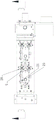
Fig. 1 is a schematic view of the front view structure of the present invention.
Fig. 2 is a schematic view of the top view structure of the present invention.
Fig. 3 is a schematic diagram of the structure B-B in fig. 2.
Fig. 4 is a partial enlarged view of M in fig. 3.
Fig. 5 is a schematic diagram of the structure C-C in fig. 3.
Fig. 6 is a schematic structural view of the guide swash block.
The names of the parts indicated by the numerical references in the above figures are as follows: the device comprises a workpiece 1, a hinge pressing block 2, a transition hinge 3, a connecting plate 4, a pull rod 5, a bridge plate 6, a cylinder I7, a cylinder I8, a guide inclined block 9, a pressing plate 10, a positioning screw I11, a support seat I12, a sliding groove 13, a hinge joint 14, a connecting bolt 15, a cylinder II 15, a pin shaft I16, a side pressing plate 17, a rotating four-axis 18, a rotating four-axis tailstock 19, a rotating cylinder III 20, a support seat II 21, an end face positioning support 22, a positioning screw II 23, a fixing seat 24, a four-axis L plate 25 and a nut 26.
Detailed Description
The present invention will be described in further detail with reference to the accompanying drawings and examples.
Example 1
A hinge type clamping machining center tool comprises a four-axis rotating mechanism and a hinge pushing mechanism, wherein the four-axis rotating mechanism is provided with the hinge pushing mechanism, the four-axis rotating mechanism comprises a bridge plate 6, the hinge pushing mechanism comprises a first oil cylinder 7, a pull rod 5, a connecting plate 4, a transition hinge 3, a hinge pressing block 2 and a guide inclined block 8, the bridge plate 6 is provided with the first oil cylinder 7, the first oil cylinder 7 is provided with the pull rod 5 and drives the pull rod 5 to move, the pull rod 5 is hinged with the connecting plate 4, the connecting plate 4 is hinged with the transition hinge 3, the transition hinge 3 is hinged with the hinge pressing block 2, the transition hinge 3 is in sliding connection with a sliding groove 12 on the guide inclined block 8, the first oil cylinder 7 drives the pull rod 5 to move downwards, the pull rod 5 drives the transition hinge 3 to slide downwards along the sliding groove 12 on the guide inclined block 8 through the connecting plate 4, meanwhile, the transition hinge 3 drives the hinge pressing block 2 to move downwards and rightwards, and the hinge pressing block 2 is contacted with the workpiece 1 and clamps the workpiece 1. The bridge plate 6 is provided with a first supporting seat 11, the first supporting seat 11 is provided with a first positioning screw 10, and the first positioning screw 10 is in contact with the workpiece 1 and clamps the workpiece 1. When the first oil cylinder 7 pulls the pull rod 5, the connecting plate 4 drives the transition hinge 3 to slide downwards along the sliding groove 12 on the guide inclined block 8, the hinge pressing block 2 moves downwards and rightwards simultaneously, after the right end face of the hinge pressing block 2 contacts the workpiece 1, the hinge pressing block continues to move downwards until the lower end face of the hinge pressing block 2 contacts and clamps the workpiece 1, and meanwhile, the first positioning screw 10 on the side face of the right end face clamps the workpiece 1.
The second supporting seat 21 is arranged on the bridge plate 6, the second supporting seat 21 is provided with a second positioning screw 23, the second positioning screw 23 is in contact with the workpiece 1 and clamps the workpiece 1, and the second positioning screw 23 is used for positioning the workpiece 1 in the length direction. The first supporting seat 11 is fixed on the bridge plate 6 through screws, the first positioning screws 10 are fixed with the first supporting seat 11 and nuts through threads, and the positioning is in the length direction and can be adjusted according to products with different lengths. The second supporting seat 21 is fixed on a long groove of the bridge plate 6, multiple holes are formed in the long groove, the position of the second supporting seat 21 is adjusted according to different product processing positions, the second positioning screw 23 is connected with the second positioning seat 21 through threads, and the second positioning screw 23 is properly adjusted according to different product widths.
The hinge clamping mechanism comprises a second oil cylinder 15, a connecting bolt 14, a hinge joint 13, a fixed seat 24, a first pin shaft 16 and a side pressure plate 17, the second oil cylinder 15 is connected with the connecting bolt 14, the connecting bolt 14 is connected with the hinge joint 13, one end of the side pressure plate 17 is hinged to the hinge joint 13, and the side pressure plate 17 is hinged to the fixed seat 24 through the first pin shaft 16. When the second oil cylinder 15 pushes the side pressing plate 17 to move rightwards, the side pressing plate 17 rotates around the first pin shaft 16, and the head of the side pressing plate 17 clamps and tightly pushes the workpiece 1.
The rotary oil cylinder clamping mechanism comprises a rotary oil cylinder III 20 and a pressing plate 9, and the pressing plate 9 is arranged on the rotary oil cylinder III 20 and drives the pressing plate 9 to rotate. The third oil cylinder 20 drives the pressing plate 9 to open outwards by 90 degrees or close inwards by 90 degrees, so that the upper workpiece 1 and the lower workpiece 1 can be conveniently moved.
The four-axis rotating mechanism further comprises a rotating four-axis 18, a four-axis tailstock 19 and a four-axis L plate 25, wherein the four-axis L plate 25 is arranged on the rotating four-axis 18, and the four-axis L plate 25 is connected with the four-axis tailstock 19 through a bridge plate 6. The four-shaft rotating mechanism has the function of driving other mechanisms to rotate and brake together with the workpiece by 360 degrees, so that the multi-surface processing of the workpiece is ensured.
The bridge plate 6 is provided with an end face positioning support 22, and the workpiece 1 is arranged on the end face positioning support 22.
The working principle of the application is as follows: two workpieces 1 are respectively arranged on the end face positioning support 22, the first positioning screw 10 and the second positioning screw 23. The side face of the hinge clamping mechanism is pre-clamped, the hinge pushing and pressing mechanism is clamped in the length direction and the height direction of one end, the oil cylinder clamping mechanism is simultaneously rotated to clamp in the height direction, one side is machined, the four-axis rotating mechanism rotates for 90 degrees, a second side is machined, and a third side is sequentially machined.
The device adopts the oil cylinder to pull the hinge inclined wedge mechanism and push the pressing block to clamp the workpiece in two directions, and only one oil cylinder is needed to clamp the workpiece in two directions. The current situation that one oil cylinder only clamps one direction in the prior art is avoided, and the situation that one direction cannot be clamped due to the fact that space is not allowed is avoided, so that the phenomenon that workpieces move in a machining process is avoided, and the quality of products is guaranteed. And the oil cylinder for clamping is saved from another aspect, and the cost is saved to a certain extent.
Adopt hinge side clamping mode, this clamping mode advantage is: 1. the side surface occupies small space, and a cutter processing space is reserved, so that the phenomenon that the cutter cannot be processed due to cutter interference and the like caused by the fact that power parts such as an oil cylinder and the like are arranged at the axial position of the rear end of the pull rod is avoided; 2. the clamping force is large, and the phenomenon that the workpiece moves due to the problem of side cutting force is avoided. 3. One end of the side pressing plate and one end of the hinge joint adopt a hole-groove structure, so that the side pressing plate can rotate freely. 4. Three stations of two parts can be processed by one-time clamping, so that the clamping times are greatly reduced. 5. Because the machining time of clamping two pieces at one time is slightly long relative to that of clamping one station and one machine tool, one machine tool operated by one person is changed into four machine tools operated by one person, and the labor cost is greatly saved.
Example 2
A hinge type clamping machining center tool comprises a four-axis rotating mechanism and a hinge pushing mechanism, wherein the four-axis rotating mechanism is provided with the hinge pushing mechanism, the four-axis rotating mechanism comprises a bridge plate 6, the hinge pushing mechanism comprises a first oil cylinder 7, a pull rod 5, a connecting plate 4, a transition hinge 3, a hinge pressing block 2 and a guide inclined block 8, the bridge plate 6 is provided with the first oil cylinder 7, the first oil cylinder 7 is provided with the pull rod 5 and drives the pull rod 5 to move, the pull rod 5 is hinged with the connecting plate 4, the connecting plate 4 is hinged with the transition hinge 3, the transition hinge 3 is hinged with the hinge pressing block 2, the transition hinge 3 is in sliding connection with a sliding groove 12 on the guide inclined block 8, the first oil cylinder 7 drives the pull rod 5 to move downwards, the pull rod 5 drives the transition hinge 3 to slide downwards along the sliding groove 12 on the guide inclined block 8 through the connecting plate 4, meanwhile, the transition hinge 3 drives the hinge pressing block 2 to move downwards and rightwards, and the hinge pressing block 2 is contacted with the workpiece 1 and clamps the workpiece 1. The bridge plate 6 is provided with a first supporting seat 11, the first supporting seat 11 is provided with a first positioning screw 10, and the first positioning screw 10 is in contact with the workpiece 1 and clamps the workpiece 1. When the first oil cylinder 7 pulls the pull rod 5, the connecting plate 4 drives the transition hinge 3 to slide downwards along the sliding groove 12 on the guide inclined block 8, the hinge pressing block 2 moves downwards and rightwards simultaneously, after the right end face of the hinge pressing block 2 contacts the workpiece 1, the hinge pressing block continues to move downwards until the lower end face of the hinge pressing block 2 contacts and clamps the workpiece 1, and meanwhile, the first positioning screw 10 on the side face of the right end face clamps the workpiece 1.
And a second supporting seat 21 is arranged on the bridge plate 6, a second positioning screw 23 is arranged on the second supporting seat 21, the second positioning screw 23 is contacted with the workpiece 1 and clamps the workpiece 1, and the second positioning screw 23 is used for positioning the workpiece 1 in the length direction. The first supporting seat 11 is fixed on the bridge plate 6 through screws, the first positioning screws 10 are fixed with the first supporting seat 11 and nuts through threads, and the positioning is in the length direction and can be adjusted according to products with different lengths. The second supporting seat 21 is fixed on a long groove of the bridge plate 6, multiple holes are formed in the long groove, the position of the second supporting seat 21 is adjusted according to different product processing positions, the second positioning screw 23 is connected with the second positioning seat 21 through threads, and the second positioning screw 23 is properly adjusted according to different product widths.
Example 3
A hinge type clamping machining center tool comprises a four-axis rotating mechanism and a hinge pushing mechanism, wherein the four-axis rotating mechanism is provided with the hinge pushing mechanism, the four-axis rotating mechanism comprises a bridge plate 6, the hinge pushing mechanism comprises a first oil cylinder 7, a pull rod 5, a connecting plate 4, a transition hinge 3, a hinge pressing block 2 and a guide inclined block 8, the bridge plate 6 is provided with the first oil cylinder 7, the first oil cylinder 7 is provided with the pull rod 5 and drives the pull rod 5 to move, the pull rod 5 is hinged with the connecting plate 4, the connecting plate 4 is hinged with the transition hinge 3, the transition hinge 3 is hinged with the hinge pressing block 2, the transition hinge 3 is in sliding connection with a sliding groove 12 on the guide inclined block 8, the first oil cylinder 7 drives the pull rod 5 to move downwards, the pull rod 5 drives the transition hinge 3 to slide downwards along the sliding groove 12 on the guide inclined block 8 through the connecting plate 4, meanwhile, the transition hinge 3 drives the hinge pressing block 2 to move downwards and rightwards, and the hinge pressing block 2 is contacted with the workpiece 1 and clamps the workpiece 1. The bridge plate 6 is provided with a first supporting seat 11, the first supporting seat 11 is provided with a first positioning screw 10, and the first positioning screw 10 is in contact with the workpiece 1 and clamps the workpiece 1. When the first oil cylinder 7 pulls the pull rod 5, the connecting plate 4 drives the transition hinge 3 to slide downwards along the sliding groove 12 on the guide inclined block 8, the hinge pressing block 2 moves downwards and rightwards simultaneously, after the right end face of the hinge pressing block 2 contacts the workpiece 1, the hinge pressing block continues to move downwards until the lower end face of the hinge pressing block 2 contacts and clamps the workpiece 1, and meanwhile, the first positioning screw 10 on the side face of the right end face clamps the workpiece 1.
And a second supporting seat 21 is arranged on the bridge plate 6, a second positioning screw 23 is arranged on the second supporting seat 21, the second positioning screw 23 is contacted with the workpiece 1 and clamps the workpiece 1, and the second positioning screw 23 is used for positioning the workpiece 1 in the length direction. The first supporting seat 11 is fixed on the bridge plate 6 through screws, the first positioning screws 10 are fixed with the first supporting seat 11 and nuts through threads, and the positioning is in the length direction and can be adjusted according to products with different lengths. The second supporting seat 21 is fixed on a long groove of the bridge plate 6, multiple holes are formed in the long groove, the position of the second supporting seat 21 is adjusted according to different product processing positions, the second positioning screw 23 is connected with the second positioning seat 21 through threads, and the second positioning screw 23 is properly adjusted according to different product widths.
The hinge clamping mechanism comprises a second oil cylinder 15, a connecting bolt 14, a hinge joint 13, a fixed seat 24, a first pin shaft 16 and a side pressure plate 17, the second oil cylinder 15 is connected with the connecting bolt 14, the connecting bolt 14 is connected with the hinge joint 13, one end of the side pressure plate 17 is hinged to the hinge joint 13, and the side pressure plate 17 is hinged to the fixed seat 24 through the first pin shaft 16. When the second oil cylinder 15 pushes the side pressing plate 17 to move rightwards, the side pressing plate 17 rotates around the first pin shaft 16, and the head of the side pressing plate 17 clamps and tightly pushes the workpiece 1.
The rotary oil cylinder clamping mechanism comprises a rotary oil cylinder III 20 and a pressing plate 9, and the pressing plate 9 is arranged on the rotary oil cylinder III 20 and drives the pressing plate 9 to rotate. The third oil cylinder 20 drives the pressing plate 9 to open outwards by 90 degrees or close inwards by 90 degrees, so that the upper workpiece 1 and the lower workpiece 1 can be conveniently moved.
Claims (7)
1. Hinge type clamping machining center frock, including four-axis rotary mechanism and hinge pushing and pressing mechanism, the last hinge pushing and pressing mechanism that is equipped with of four-axis rotary mechanism, its characterized in that: the four-axis rotating mechanism comprises a bridge plate (6), the hinge pushing and pressing mechanism comprises a first oil cylinder (7), a pull rod (5), a connecting plate (4), a transition hinge (3), a hinge pressing block (2) and a guide inclined block (8), the first oil cylinder (7) is arranged on the bridge plate (6), the first oil cylinder (7) is provided with the pull rod (5) and drives the pull rod (5) to move, the pull rod (5) is hinged with the connecting plate (4), the connecting plate (4) is hinged with the transition hinge (3), the transition hinge (3) is hinged with the hinge pressing block (2), the transition hinge (3) is in sliding connection with a sliding groove (12) on the guide inclined block (8), the first oil cylinder (7) drives the pull rod (5) to move downwards, the pull rod (5) drives the transition hinge (3) to slide downwards along the sliding groove (12) on the guide inclined block (8) through the connecting plate (4), and the transition hinge (3) drives the hinge pressing block (2) to move downwards and rightwards, the hinge pressing block (2) is contacted with the workpiece (1) and clamps the workpiece (1).
2. The hinge type clamping machining center tool according to claim 1, characterized in that: a first supporting seat (11) is arranged on the bridge plate (6), a first positioning screw (10) is arranged on the first supporting seat (11), and the first positioning screw (10) is in contact with the workpiece (1) and clamps the workpiece (1).
3. The hinge type clamping machining center tool according to claim 1, characterized in that: and a second supporting seat (21) is arranged on the bridge plate (6), a second positioning screw (23) is arranged on the second supporting seat (21), and the second positioning screw (23) is contacted with the workpiece (1) and clamps the workpiece (1).
4. The hinge type clamping machining center tool according to claim 1, characterized in that: the hinge clamping mechanism comprises a second oil cylinder (15), a connecting bolt (14), a hinge joint (13), a fixed seat (24), a first pin shaft (16) and a side pressure plate (17), the second oil cylinder (15) is connected with the connecting bolt (14), the connecting bolt (14) is connected with the hinge joint (13), one end of the side pressure plate (17) is hinged to the hinge joint (13), and the side pressure plate (17) is hinged to the fixed seat (24) through the first pin shaft (16).
5. The hinge type clamping machining center tool according to claim 1, characterized in that: the device is characterized by further comprising a rotary oil cylinder clamping mechanism, wherein the rotary oil cylinder clamping mechanism comprises a rotary oil cylinder III (20) and a pressing plate (9), and the pressing plate (9) is arranged on the rotary oil cylinder III (20) and drives the pressing plate (9) to rotate.
6. The hinge type clamping machining center tool according to claim 1, characterized in that: the four-axis rotating mechanism further comprises a rotating four-axis (18), a four-axis tailstock (19) and a four-axis L plate (25), wherein the four-axis L plate (25) is arranged on the rotating four-axis (18), and the four-axis L plate (25) is connected with the four-axis tailstock (19) through a bridge plate (6).
7. The hinge type clamping machining center tool according to claim 6, characterized in that: an end face positioning support (22) is arranged on the bridge plate (6), and the workpiece (1) is installed on the end face positioning support (22).
Priority Applications (1)
| Application Number | Priority Date | Filing Date | Title |
|---|---|---|---|
| CN202121291412.7U CN217167456U (en) | 2021-06-09 | 2021-06-09 | Hinge type clamping machining center tool |
Applications Claiming Priority (1)
| Application Number | Priority Date | Filing Date | Title |
|---|---|---|---|
| CN202121291412.7U CN217167456U (en) | 2021-06-09 | 2021-06-09 | Hinge type clamping machining center tool |
Publications (1)
| Publication Number | Publication Date |
|---|---|
| CN217167456U true CN217167456U (en) | 2022-08-12 |
Family
ID=82706706
Family Applications (1)
| Application Number | Title | Priority Date | Filing Date |
|---|---|---|---|
| CN202121291412.7U Active CN217167456U (en) | 2021-06-09 | 2021-06-09 | Hinge type clamping machining center tool |
Country Status (1)
| Country | Link |
|---|---|
| CN (1) | CN217167456U (en) |
Cited By (2)
| Publication number | Priority date | Publication date | Assignee | Title |
|---|---|---|---|---|
| CN113263338A (en) * | 2021-06-09 | 2021-08-17 | 浙江科力车辆控制系统有限公司 | Hinge type clamping machining center tool |
| CN115570412A (en) * | 2022-10-21 | 2023-01-06 | 莱州鸿源台钳制造有限公司 | Universal clamp for movable vice body of processing bench vice |
-
2021
- 2021-06-09 CN CN202121291412.7U patent/CN217167456U/en active Active
Cited By (3)
| Publication number | Priority date | Publication date | Assignee | Title |
|---|---|---|---|---|
| CN113263338A (en) * | 2021-06-09 | 2021-08-17 | 浙江科力车辆控制系统有限公司 | Hinge type clamping machining center tool |
| CN113263338B (en) * | 2021-06-09 | 2024-12-03 | 浙江科力车辆控制系统有限公司 | Hinge clamping machining center tooling |
| CN115570412A (en) * | 2022-10-21 | 2023-01-06 | 莱州鸿源台钳制造有限公司 | Universal clamp for movable vice body of processing bench vice |
Similar Documents
| Publication | Publication Date | Title |
|---|---|---|
| CN207087314U (en) | Porous part automatic multi-station tapping device with automatic deviation rectifying function | |
| CN211661532U (en) | But angle regulation's jig | |
| CN114619063A (en) | Mechanical chuck clamp and workpiece double-face assembling machine | |
| CN216577175U (en) | Opposite vertex fixture mechanism and machine tool | |
| CN216989926U (en) | Mechanical chuck clamp and workpiece double-face assembling machine | |
| CN215239513U (en) | Chain type tool magazine assembly for double-spindle horizontal machining center | |
| CN215035561U (en) | Automatic centering fixture for numerical control polar coordinate high-speed drilling machine tool | |
| CN113263338A (en) | Hinge type clamping machining center tool | |
| CN219234582U (en) | Turnover fixing tool fixture of CNC (computerized numerical control) lathe | |
| JPH05285756A (en) | Multipurpose finishing machine | |
| CN218696223U (en) | Positioning device of fixed beam gantry machining center | |
| CN215393902U (en) | Four-axis anchor clamps of convenient debugging | |
| CN217666505U (en) | Spiral double-sided chuck for laser pipe cutting machine | |
| CN115519383A (en) | Machine tool hydraulic clamping device suitable for machining of machine tool plate | |
| CN222986376U (en) | Auxiliary device for machine tool machining | |
| CN215747076U (en) | Kettle cutting machine | |
| CN223353624U (en) | Turntable type double-workbench clamping mechanism of numerical control machine tool | |
| CN219704281U (en) | Work piece hydraulic pressure centre gripping positioning mechanism | |
| CN118023978B (en) | Workpiece fixing device based on numerical control lathe | |
| CN223146173U (en) | A three-way rotary table drilling rig | |
| CN216938715U (en) | Special unilateral self-centering rotary table for sawing machine | |
| CN220029375U (en) | Adjustable pneumatic three-jaw clamping device | |
| CN219768288U (en) | Centering clamping jaw | |
| CN220920957U (en) | Radial drilling machine for machining pipe | |
| CN216829781U (en) | Be applied to tight structure of clamp of numerical control rip cutting automatic lathe |
Legal Events
| Date | Code | Title | Description |
|---|---|---|---|
| GR01 | Patent grant | ||
| GR01 | Patent grant |