CN217165763U - Waste treatment device for alumina lining brick - Google Patents
Waste treatment device for alumina lining brick Download PDFInfo
- Publication number
- CN217165763U CN217165763U CN202220023186.2U CN202220023186U CN217165763U CN 217165763 U CN217165763 U CN 217165763U CN 202220023186 U CN202220023186 U CN 202220023186U CN 217165763 U CN217165763 U CN 217165763U
- Authority
- CN
- China
- Prior art keywords
- box body
- fixed
- semi
- alumina
- waste treatment
- Prior art date
- Legal status (The legal status is an assumption and is not a legal conclusion. Google has not performed a legal analysis and makes no representation as to the accuracy of the status listed.)
- Active
Links
- 239000002699 waste material Substances 0.000 title claims abstract description 32
- 239000011449 brick Substances 0.000 title claims abstract description 21
- PNEYBMLMFCGWSK-UHFFFAOYSA-N aluminium oxide Inorganic materials [O-2].[O-2].[O-2].[Al+3].[Al+3] PNEYBMLMFCGWSK-UHFFFAOYSA-N 0.000 title claims abstract description 13
- 238000000227 grinding Methods 0.000 claims abstract description 28
- 230000000903 blocking effect Effects 0.000 claims abstract description 23
- 239000011265 semifinished product Substances 0.000 claims abstract description 21
- 230000000149 penetrating effect Effects 0.000 claims abstract description 18
- 239000000463 material Substances 0.000 claims description 11
- 230000007246 mechanism Effects 0.000 claims description 9
- 230000006835 compression Effects 0.000 claims description 2
- 238000007906 compression Methods 0.000 claims description 2
- 238000000034 method Methods 0.000 claims 1
- 238000007599 discharging Methods 0.000 abstract description 2
- 230000000694 effects Effects 0.000 description 3
- 230000009467 reduction Effects 0.000 description 3
- 239000000126 substance Substances 0.000 description 3
- BYFGZMCJNACEKR-UHFFFAOYSA-N aluminium(i) oxide Chemical compound [Al]O[Al] BYFGZMCJNACEKR-UHFFFAOYSA-N 0.000 description 2
- 230000004888 barrier function Effects 0.000 description 2
- 239000004568 cement Substances 0.000 description 2
- 239000000919 ceramic Substances 0.000 description 2
- 239000011248 coating agent Substances 0.000 description 2
- 238000000576 coating method Methods 0.000 description 2
- 239000003814 drug Substances 0.000 description 2
- 238000001125 extrusion Methods 0.000 description 2
- 239000003973 paint Substances 0.000 description 2
- 239000000049 pigment Substances 0.000 description 2
- 239000000047 product Substances 0.000 description 2
- 238000005299 abrasion Methods 0.000 description 1
- 238000009835 boiling Methods 0.000 description 1
- 150000001875 compounds Chemical class 0.000 description 1
- 238000005260 corrosion Methods 0.000 description 1
- 230000007797 corrosion Effects 0.000 description 1
- 239000013078 crystal Substances 0.000 description 1
- 238000010586 diagram Methods 0.000 description 1
- 238000005265 energy consumption Methods 0.000 description 1
- 239000008187 granular material Substances 0.000 description 1
- 238000004519 manufacturing process Methods 0.000 description 1
- 238000002844 melting Methods 0.000 description 1
- 230000008018 melting Effects 0.000 description 1
- 230000004048 modification Effects 0.000 description 1
- 238000012986 modification Methods 0.000 description 1
- 238000010298 pulverizing process Methods 0.000 description 1
- 239000011819 refractory material Substances 0.000 description 1
Images


Classifications
-
- Y—GENERAL TAGGING OF NEW TECHNOLOGICAL DEVELOPMENTS; GENERAL TAGGING OF CROSS-SECTIONAL TECHNOLOGIES SPANNING OVER SEVERAL SECTIONS OF THE IPC; TECHNICAL SUBJECTS COVERED BY FORMER USPC CROSS-REFERENCE ART COLLECTIONS [XRACs] AND DIGESTS
- Y02—TECHNOLOGIES OR APPLICATIONS FOR MITIGATION OR ADAPTATION AGAINST CLIMATE CHANGE
- Y02P—CLIMATE CHANGE MITIGATION TECHNOLOGIES IN THE PRODUCTION OR PROCESSING OF GOODS
- Y02P40/00—Technologies relating to the processing of minerals
- Y02P40/60—Production of ceramic materials or ceramic elements, e.g. substitution of clay or shale by alternative raw materials, e.g. ashes
Landscapes
- Crushing And Grinding (AREA)
Abstract
The utility model relates to the technical field of alumina lining bricks, and provides a waste treatment device for alumina lining bricks, which comprises a box body, a feed inlet, a first blocking net, a first crushing toothed plate, a semi-finished product feed hopper and a fixed grinding disc, wherein the right side of the upper surface of the box body is provided with the feed inlet in a penetrating way, the upper part of the inner side surface of the box body is fixedly provided with a first blocking way, the upper part of the inner side surface of the box body is fixedly provided with the first crushing toothed plate, the right side surface of the box body is provided with the semi-finished product feed hopper in a penetrating way, the inner center of the box body is provided with the fixed grinding disc, the lower part of the inner side surface of the box body is fixedly provided with a second blocking net, and the lower part of the right side surface of the box body is provided with a semi-finished product discharge pipe in a penetrating way; through being provided with semi-manufactured goods discharging pipe and semi-manufactured goods feeder hopper, grind through rubbing crusher constructs and mill and directly add to the box through semi-manufactured goods feeder hopper and grind, need not to carry out the one-level once more and smashes, increase the work efficiency when smashing.
Description
Technical Field
The utility model relates to an alumina lining brick technical field especially relates to an alumina lining is waste material processing apparatus for brick.
Background
The chemical formula Al2O 3. Is a high-hardness compound, has a melting point of 2054 ℃ and a boiling point of 2980 ℃, can be used for preparing an ionizable ionic crystal at high temperature, and is commonly used for manufacturing refractory materials;
the alumina lining brick is a product for the wear-resistant lining of the ball mill, is widely applied to industries such as ceramics, cement, paint, pigment, chemical industry, medicine, coating and the like, has the characteristics of high hardness, large density, low abrasion, good regularity, corrosion resistance and the like, is used for the wear-resistant lining of the ball mill, is widely applied to industries such as ceramics, cement, paint, pigment, chemical industry, medicine, coating and the like, can effectively improve the grinding efficiency, reduces the grinding cost and reduces the product pollution.
When the waste material for the alumina lining brick is handled, reducing mechanism carries out multi-stage reduction to the waste material to need to use usually, screen again after smashing, when current reducing mechanism carries out multi-stage reduction again, the complete waste material of not smashing all need add the feeder hopper again and carry out multi-stage reduction once more, and the waste material through preliminary crushing carries out one-level once more and smashes, and the waste material after smashing many times is granule less usually, carry out one-level once more and smash not only reduce efficiency, and increase energy consumption and cost.
SUMMERY OF THE UTILITY MODEL
The utility model aims at solving the problems existing in the prior art and providing a waste treatment device for alumina lining bricks.
In order to achieve the above purpose, the utility model adopts the following technical scheme:
a waste treatment device for alumina lining bricks comprises a box body, a feed inlet, a first blocking net, a first crushing toothed plate, a semi-finished product feed hopper and a fixed grinding disc, wherein the feed inlet is arranged on the right side of the upper surface of the box body in a penetrating manner, the first blocking net is fixedly arranged above the inner side surface of the box body, the first crushing toothed plate is fixedly arranged above the inner side surface of the box body, the semi-finished product feed hopper is arranged on the right side surface of the box body in a penetrating manner, the fixed grinding disc is arranged in the center of the inner side of the box body, a second blocking net is fixedly arranged below the inner side surface of the box body, a semi-finished product discharge pipe is arranged below the right side surface of the box body in a penetrating manner, a guide plate is fixedly arranged at the bottom of the inner side surface of the box body, a discharge pipe is arranged at the bottom of the left side surface of the box body in a penetrating manner, and a second rotating motor is fixedly arranged at the center of the bottom surface of the box body, the output end of the second rotating motor is fixedly provided with a rotating grinding disc through a rotating rod;
and a crushing mechanism is fixedly arranged at the bottom of the inner side surface of the box body.
Preferably, the box body comprises a first rotating motor, a driving gear, a rotating shaft, a driven gear and a cam;
the fixed top surface left side that sets up in the box of first rotating electrical machines, the fixed driving gear that is provided with of output of first rotating electrical machines, the upper surface left side of box is provided with the pivot through the bearing rotation, the fixed driven gear that is provided with in top of pivot, the fixed cam that is provided with in bottom of pivot.
Preferably, the diameter of the driving gear is 5-8 times of the diameter of the driven gear, and the driving gear and the driven gear are mutually clamped.
Preferably, the crushing mechanism comprises a rectangular sleeve, a buffer spring, a second crushing toothed plate, a penetrating rod and a squeezing plate;
the utility model discloses a crushing device for refrigerator, including box, rectangle sleeve, right side fixed surface, buffer spring, crushing pinion rack, the fixed pinion rack that runs through of left side surface central authorities of second, the rectangle sleeve is fixed to be set up in the inside surface top of box, the telescopic right side fixed surface of rectangle is provided with many buffer spring, buffer spring's right-hand member is fixed to be provided with the crushing pinion rack of second, the fixed pole that runs through that is provided with in left side surface central authorities of the crushing pinion rack of second, the fixed stripper plate that is provided with in left end that runs through the pole.
Preferably, the first crushing toothed plate and the second crushing toothed plate are matched.
Preferably, the cam is located on the left side of the compression plate.
Preferably, the upper surface embedding of fixed mill is provided with the funnel shape groove, and the bottom surface of fixed mill is hugged closely to the upper surface of rotatory mill.
Preferably, the second blocking net is inclined towards the right side by 30 degrees, and the semi-finished product discharge pipe is positioned at the right end of the second blocking net.
Preferably, the material guide plate is inclined 20 degrees downwards to the left.
Has the advantages that:
1. through being provided with semi-manufactured goods discharging pipe and semi-manufactured goods feeder hopper, grind through rubbing crusher constructs and mill and directly add to the box through semi-manufactured goods feeder hopper and grind, need not to carry out the one-level once more and smashes, increase the work efficiency when smashing.
2. Through being provided with rubbing crusher structure, fixed mill and rotatory mill, drive the driving gear through first rotating electrical machines, driven gear, pivot and cam rotate, make cam striking stripper plate, the stripper plate drives the second through running through the pole and smashes the pinion rack and move towards the right side, make the first pinion rack of smashing of second cooperation carry out preliminary crushing with the waste material, and the waste material after smashing enters into between fixed mill and the rotatory mill through the funnel-shaped groove on the fixed mill, drive fixed mill through the second rotating electrical machines and rotate, reach the kibbling effect of second grade.
Drawings
In order to more clearly illustrate the technical solutions of the embodiments of the present invention, the drawings that are required to be used in the embodiments will be briefly described below, it should be understood that the following drawings only illustrate some embodiments of the present invention, and therefore should not be considered as limiting the scope, and for those skilled in the art, other related drawings can be obtained according to the drawings without inventive efforts.
FIG. 1 is a schematic sectional view of the overall structure of the present invention;
FIG. 2 is an enlarged schematic view of the structure at A of FIG. 1 according to the present invention;
FIG. 3 is a schematic view of the overall structure of the middle pulverizing mechanism of the present invention;
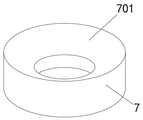
fig. 4 is the overall structure diagram of the middle fixed millstone of the utility model.
Illustration of the drawings: 1. a box body; 101. a first rotating electrical machine; 102. a driving gear; 103. a rotating shaft; 104. a driven gear; 105. a cam; 2. a feed inlet; 3. a first blocking net, 4, a rectangular sleeve; 401. a buffer spring; 402. a second crushing toothed plate; 403. penetrating the rod; 404. a pressing plate; 5. a first crushing toothed plate; 6. a semi-finished product feed hopper; 7. fixing the grinding disc; 701. a funnel-shaped groove; 8. a second barrier net; 9. a semi-finished product discharge pipe; 10. a material guide plate; 11. a discharge pipe; 12. a second rotating electrical machine; 13. rotating the rod; 14. the grinding disc is rotated.
Detailed Description
In order to make the objects, technical solutions and advantages of the embodiments of the present invention clearer, the embodiments of the present invention will be clearly and completely described below with reference to the accompanying drawings in the embodiments of the present invention, and it is obvious that the described embodiments are some, but not all, embodiments of the present invention.
Referring to fig. 1-4, a waste treatment device for alumina lining bricks comprises a box body 1, a feed inlet 2, a first blocking net 3, a first crushing toothed plate 5, a semi-finished product feed hopper 6 and a fixed grinding disc 7, wherein the feed inlet 2 is arranged on the right side of the upper surface of the box body 1 in a penetrating manner, a first blocking net 3 is fixedly arranged above the inner side surface of the box body 1, the first crushing toothed plate 5 is fixedly arranged above the inner right side surface of the box body 1, the semi-finished product feed hopper 6 is arranged on the right side surface of the box body 1 in a penetrating manner, the fixed grinding disc 7 is arranged in the center of the inner side of the box body 1, a second blocking net 8 is fixedly arranged below the inner side surface of the box body 1, a semi-finished product discharge pipe 9 is arranged below the right side surface of the box body 1 in a penetrating manner, a guide plate 10 is fixedly arranged at the bottom of the inner side surface of the box body 1, a discharge pipe 11 is arranged at the bottom of the left side surface of the box body 1 in a penetrating manner, and a second rotating motor 12 is fixedly arranged in the center of the bottom surface of the box body 1, the output end of the second rotating motor 12 is fixedly provided with a rotating grinding disc 14 through a rotating rod 13;
the bottom of the inner side surface of the box body 1 is fixedly provided with a crushing mechanism.
In this embodiment, the case 1 includes a first rotating electric machine 101, a driving gear 102, a rotating shaft 103, a driven gear 104, and a cam 105;
the first rotating motor 101 is fixedly arranged on the left side of the top surface of the box body 1, the output end of the first rotating motor 101 is fixedly provided with a driving gear 102, the left side of the upper surface of the box body 1 is rotatably provided with a rotating shaft 103 through a bearing, the top of the rotating shaft 103 is fixedly provided with a driven gear 104, and the bottom of the rotating shaft 103 is fixedly provided with a cam 105.
In this embodiment, the diameter of the driving gear 102 is 5-8 times of the diameter of the driven gear 104, and the driving gear 102 and the driven gear 104 are clamped with each other, so that the driving gear 102 drives the driven gear 104 to rotate, and the cam 105 rotates conveniently.
In this embodiment, the crushing mechanism includes a rectangular sleeve 4, a buffer spring 401, a second crushing tooth plate 402, a through rod 403 and a pressing plate 404;
the rectangle sleeve 4 is fixed to be set up in the inside surface top of box 1, and the right side fixed surface of rectangle sleeve 4 is provided with many buffer spring 401, and buffer spring 401's right-hand member is fixed and is provided with second crushing pinion rack 402, and the left side fixed surface central authorities of second crushing pinion rack 402 are provided with and run through pole 403, and the left end that runs through pole 403 is fixed and is provided with stripper plate 404.
In this embodiment, first crushing pinion rack 5 and second crushing pinion rack 402 are supporting mutually, make things convenient for first crushing pinion rack 5 to cooperate the second crushing pinion rack 402 to smash the waste material.
In this embodiment, the cam 105 is located at the left side of the pressing plate 404, which facilitates the pressing of the pressing plate 404 by the cam 105.
In this embodiment, the funnel-shaped groove 701 is embedded in the upper surface of the fixed grinding disc 7, and the upper surface of the rotating grinding disc 14 is tightly attached to the bottom surface of the fixed grinding disc 7, so that waste materials can enter between the fixed grinding disc 7 and the rotating grinding disc 14 conveniently.
In this embodiment, the second blocking net 8 is inclined to the right by 30 °, and the semi-finished product discharge pipe 9 is located at the right end of the second blocking net 8. The filtered waste material of the second barrier net 8 is conveniently discharged from the semi-finished product discharge pipe 9.
In this embodiment, the material guiding plate 10 is inclined 20 degrees downward to the left, which facilitates the discharge of the material.
The working principle is as follows:
when the waste crushing device is used, waste materials for alumina lining bricks are added into the box body 1 through the feeding hole 2, then the first rotating motor 101 is started, the first rotating motor 101 drives the driving gear 102 to rotate, so that the driving gear 102 drives the driven gear 104, the rotating shaft 103 and the cam 105 rotate, so that the cam 105 impacts the extrusion plate 404, the extrusion plate 404 drives the second crushing toothed plate 402 to move towards the right side through the penetrating rod 403, so that the second crushing toothed plate 402 is matched with the first crushing toothed plate 5 to crush the waste materials preliminarily, the crushed waste materials pass through the first blocking net 3 to fall downwards, enter between the fixed grinding disc 7 and the rotating grinding disc 14 through the funnel-shaped groove 701 on the fixed grinding disc 7, the second rotating motor 12 drives the rotating grinding disc 14 to rotate, and the fixed grinding disc 7 is matched with the rotating grinding disc 14 to crush the waste materials secondarily;
the crushed materials are filtered through a second blocking net 8, the materials which are not completely crushed are discharged from a semi-finished product discharge pipe 9, are added into the box body 1 again through a semi-finished product feed hopper 6, and are crushed again through a fixed grinding disc 7 and a rotary grinding disc 14, so that the crushing effect is achieved;
the completely crushed waste material passes through the second blocking net 8, falls onto the material guide plate 10 and is discharged from the material discharge pipe 11.
The above is only the preferred embodiment of the present invention, and it should be noted that, for those skilled in the art, without departing from the concept of the present invention, several modifications and improvements can be made, which should also be regarded as the protection scope of the present invention, and these will not affect the effect of the implementation of the present invention and the practicability of the patent.
Claims (9)
1. A waste treatment device for alumina lining bricks is characterized in that; the method comprises the following steps:
the feeding hole (2) is arranged on the right side of the upper surface of the box body (1) in a penetrating mode;
the first blocking net (3), the first blocking net (3) is fixedly arranged above the inner side of the box body (1);
the first crushing toothed plate (5), the first crushing toothed plate (5) is fixedly arranged above the inner right side surface of the box body (1);
the semi-finished product feeding hopper (6), the semi-finished product feeding hopper (6) is arranged above the right side surface of the box body (1) in a penetrating mode;
the fixed grinding disc (7) is fixedly arranged in the center of the inner side of the box body (1);
the second blocking net (8), the second blocking net (8) is fixedly arranged below the inner side surface of the box body (1);
the semi-finished product discharge pipe (9), the semi-finished product discharge pipe (9) penetrates through the right side surface of the box body (1);
the material guide plate (10), the material guide plate (10) is fixedly arranged at the bottom of the inner side surface of the box body (1);
the discharge pipe (11) penetrates through the discharge pipe (11) and is arranged below the left side surface of the box body (1);
the second rotating motor (12), the second rotating motor (12) is fixedly arranged in the center of the bottom surface of the box body (1);
the rotating rod (13), the rotating rod (13) is fixedly arranged at the output end of the second rotating motor (12);
the rotary grinding disc (14), the rotary grinding disc (14) is fixedly arranged at the top of the rotary rod (13);
and a crushing mechanism is fixedly arranged at the bottom of the inner side surface of the box body (1).
2. The waste treatment apparatus for alumina-lined bricks according to claim 1, wherein: the box body (1) comprises a first rotating motor (101), a driving gear (102), a rotating shaft (103), a driven gear (104) and a cam (105);
first rotating electrical machines (101) are fixed to be set up in the top surface left side of box (1), the fixed driving gear (102) that is provided with of output of first rotating electrical machines (101), the upper surface left side of box (1) is provided with pivot (103) through the bearing rotation, the fixed driven gear (104) that is provided with in top of pivot (103), the fixed cam (105) that is provided with in bottom of pivot (103).
3. The waste treatment apparatus for alumina-lined bricks according to claim 2, wherein: the diameter of the driving gear (102) is 5-8 times of that of the driven gear (104), and the driving gear (102) and the driven gear (104) are mutually clamped.
4. The waste treatment apparatus for alumina-lined bricks according to claim 2, wherein: the crushing mechanism comprises a rectangular sleeve (4), a buffer spring (401), a second crushing toothed plate (402), a penetrating rod (403) and a squeezing plate (404);
the fixed inboard surface top that sets up in box (1) in rectangle sleeve (4), the right side fixed surface of rectangle sleeve (4) is provided with many buffer spring (401), the fixed pinion rack (402) of second that is provided with of right-hand member of buffer spring (401), the fixed penetrating rod (403) that is provided with in left side surface central authorities of the pinion rack (402) is smashed to the second, the fixed stripper plate (404) that is provided with in left end that penetrates rod (403).
5. The waste treatment apparatus for alumina-lined bricks according to claim 4, wherein: the first crushing toothed plate (5) is matched with the second crushing toothed plate (402).
6. The waste treatment apparatus for alumina-lined bricks according to claim 4, wherein: the cam (105) is located on the left side of the compression plate (404).
7. The waste treatment apparatus for alumina-lined bricks according to claim 1, wherein: the upper surface embedding of fixed mill (7) is provided with funnel shape groove (701), and the bottom surface of fixed mill (7) is hugged closely to the upper surface of rotatory mill (14).
8. The waste treatment apparatus for alumina-lined bricks according to claim 1, wherein: the second blocking net (8) is inclined towards the right side by 30 degrees, and the semi-finished product discharge pipe (9) is arranged at the right end of the second blocking net (8).
9. The waste treatment apparatus for alumina-lined bricks according to claim 1, wherein: the material guide plate (10) is inclined 20 degrees downwards to the left.
Priority Applications (1)
| Application Number | Priority Date | Filing Date | Title |
|---|---|---|---|
| CN202220023186.2U CN217165763U (en) | 2022-01-07 | 2022-01-07 | Waste treatment device for alumina lining brick |
Applications Claiming Priority (1)
| Application Number | Priority Date | Filing Date | Title |
|---|---|---|---|
| CN202220023186.2U CN217165763U (en) | 2022-01-07 | 2022-01-07 | Waste treatment device for alumina lining brick |
Publications (1)
| Publication Number | Publication Date |
|---|---|
| CN217165763U true CN217165763U (en) | 2022-08-12 |
Family
ID=82734236
Family Applications (1)
| Application Number | Title | Priority Date | Filing Date |
|---|---|---|---|
| CN202220023186.2U Active CN217165763U (en) | 2022-01-07 | 2022-01-07 | Waste treatment device for alumina lining brick |
Country Status (1)
| Country | Link |
|---|---|
| CN (1) | CN217165763U (en) |
Cited By (1)
| Publication number | Priority date | Publication date | Assignee | Title |
|---|---|---|---|---|
| CN119406552A (en) * | 2025-01-07 | 2025-02-11 | 宿迁和天下建材科技有限公司 | A fiber concrete additive fiber crushing device |
-
2022
- 2022-01-07 CN CN202220023186.2U patent/CN217165763U/en active Active
Cited By (1)
| Publication number | Priority date | Publication date | Assignee | Title |
|---|---|---|---|---|
| CN119406552A (en) * | 2025-01-07 | 2025-02-11 | 宿迁和天下建材科技有限公司 | A fiber concrete additive fiber crushing device |
Similar Documents
| Publication | Publication Date | Title |
|---|---|---|
| CN216368104U (en) | Crushing device for preparing reduced iron powder | |
| CN216910561U (en) | Dedicated crushing equipment of hard ore | |
| CN117861268A (en) | Mineral source fertilizer production device and method for wind-blown sand saline-alkali soil | |
| CN208554447U (en) | A kind of grinding device of automated material | |
| CN213254777U (en) | A kind of comminutor | |
| CN210522708U (en) | Ultra-micro mill | |
| CN210585148U (en) | Silicon material crusher with secondary crushing function | |
| CN216099898U (en) | High-efficient rubbing crusher of usefulness is handled to old and useless plastic bag | |
| CN221245330U (en) | A superfine pulverizer for calcium stearate | |
| CN213408985U (en) | Grinder that coating processing production used | |
| CN217392585U (en) | Crushing device capable of screening cement auxiliary materials | |
| CN211099407U (en) | Online rubbing crusher of system cup | |
| CN212820290U (en) | High polymer material pulverizer | |
| CN210965333U (en) | Fertilizer miscellany material multilayer shear type breaker | |
| CN216573481U (en) | Ultra-fine calcium carbonate grinding device | |
| CN210522688U (en) | Convenient material crusher of ejection of compact | |
| CN208542302U (en) | A kind of wet ball mill convenient for operation | |
| CN217615028U (en) | Millstone type soil crushing device | |
| CN221360032U (en) | Grinder for processing calcium silicate board | |
| CN222829748U (en) | Discharging device for limestone crusher | |
| CN218609770U (en) | Grinding device for graphite processing | |
| CN215353602U (en) | Jaw crusher convenient to carry out recovery processing to disintegrating slag | |
| CN221132440U (en) | Sand and stone crushing equipment for building construction | |
| CN218609608U (en) | Material discharging mechanism for crusher | |
| CN220634697U (en) | Feeding structure of pulverizer |
Legal Events
| Date | Code | Title | Description |
|---|---|---|---|
| GR01 | Patent grant | ||
| GR01 | Patent grant |