CN217163338U - Energy-saving type wastewater filtering equipment for industrial water saving - Google Patents
Energy-saving type wastewater filtering equipment for industrial water saving Download PDFInfo
- Publication number
- CN217163338U CN217163338U CN202123231855.XU CN202123231855U CN217163338U CN 217163338 U CN217163338 U CN 217163338U CN 202123231855 U CN202123231855 U CN 202123231855U CN 217163338 U CN217163338 U CN 217163338U
- Authority
- CN
- China
- Prior art keywords
- fixed
- rod
- casing
- saving
- plate
- Prior art date
- Legal status (The legal status is an assumption and is not a legal conclusion. Google has not performed a legal analysis and makes no representation as to the accuracy of the status listed.)
- Expired - Fee Related
Links
- 239000002351 wastewater Substances 0.000 title claims abstract description 18
- 238000001914 filtration Methods 0.000 title claims abstract description 15
- 239000008235 industrial water Substances 0.000 title claims abstract description 14
- 238000004075 wastewater filtration Methods 0.000 claims abstract description 12
- 230000007246 mechanism Effects 0.000 claims description 14
- 230000000903 blocking effect Effects 0.000 claims description 11
- 238000007789 sealing Methods 0.000 claims description 9
- 238000004519 manufacturing process Methods 0.000 abstract description 5
- 239000010842 industrial wastewater Substances 0.000 abstract description 4
- 239000002910 solid waste Substances 0.000 abstract description 2
- 238000004065 wastewater treatment Methods 0.000 abstract description 2
- XLYOFNOQVPJJNP-UHFFFAOYSA-N water Substances O XLYOFNOQVPJJNP-UHFFFAOYSA-N 0.000 description 10
- 238000010586 diagram Methods 0.000 description 2
- 238000000034 method Methods 0.000 description 2
- 239000010865 sewage Substances 0.000 description 2
- 230000009471 action Effects 0.000 description 1
- 230000009286 beneficial effect Effects 0.000 description 1
- 238000004140 cleaning Methods 0.000 description 1
- 238000010924 continuous production Methods 0.000 description 1
- 239000013505 freshwater Substances 0.000 description 1
- 230000005484 gravity Effects 0.000 description 1
- 239000012535 impurity Substances 0.000 description 1
- 230000004048 modification Effects 0.000 description 1
- 238000012986 modification Methods 0.000 description 1
- 230000008569 process Effects 0.000 description 1
- 230000009467 reduction Effects 0.000 description 1
- 239000007787 solid Substances 0.000 description 1
- 230000003068 static effect Effects 0.000 description 1
- 238000003911 water pollution Methods 0.000 description 1
Images


Classifications
-
- Y—GENERAL TAGGING OF NEW TECHNOLOGICAL DEVELOPMENTS; GENERAL TAGGING OF CROSS-SECTIONAL TECHNOLOGIES SPANNING OVER SEVERAL SECTIONS OF THE IPC; TECHNICAL SUBJECTS COVERED BY FORMER USPC CROSS-REFERENCE ART COLLECTIONS [XRACs] AND DIGESTS
- Y02—TECHNOLOGIES OR APPLICATIONS FOR MITIGATION OR ADAPTATION AGAINST CLIMATE CHANGE
- Y02W—CLIMATE CHANGE MITIGATION TECHNOLOGIES RELATED TO WASTEWATER TREATMENT OR WASTE MANAGEMENT
- Y02W10/00—Technologies for wastewater treatment
- Y02W10/30—Wastewater or sewage treatment systems using renewable energies
- Y02W10/37—Wastewater or sewage treatment systems using renewable energies using solar energy
Landscapes
- Filtration Of Liquid (AREA)
Abstract
本实用新型公开一种用于工业节水的节能型废水过滤设备,属于工业无废水处理技术领域,包括壳体,所述壳体的内部转动连接有往复丝杆,所述往复丝杆的外侧滑动连接有滑块,所述滑块的底部固定有刷板,且刷板与壳体的内侧壁滑动连接,所述往复丝杆的一端贯穿并延伸至壳体的外侧,所述往复丝杆的一端固定有第一齿轮,所述壳体的一侧固定有固定板,所述固定板的一侧滑动连接有齿板,且齿板与第一齿轮相啮合。本实用新型能够无需电力资源即可对该废水过滤设备中堆积堵塞网面的固体废料推动至收集框内,提高废水的过滤效率,节约电力资源,且无需配备电力设备生产成本降低,从而提高了该工业废水过滤设备的节能性,满足了企业的生产需求。

The utility model discloses an energy-saving waste water filtering device for industrial water saving, belonging to the technical field of industrial non-wastewater treatment. A slider is slidably connected, a brush plate is fixed at the bottom of the slider, and the brush plate is slidably connected with the inner side wall of the casing. One end of the reciprocating screw penetrates and extends to the outside of the casing. A first gear is fixed on one end of the casing, a fixed plate is fixed on one side of the casing, a toothed plate is slidably connected to one side of the fixed plate, and the toothed plate is engaged with the first gear. The utility model can push the solid waste accumulated in the waste water filtration equipment and block the mesh surface into the collection frame without power resources, thereby improving the filtration efficiency of waste water, saving power resources, and reducing the production cost without the need for equipping power equipment, thereby improving the efficiency of the waste water filter. The energy saving of the industrial wastewater filtration equipment meets the production needs of the enterprise.
Description
技术领域technical field
本实用新型涉及一种废水过滤设备,特别是涉及一种用于工业节水的节能型废水过滤设备,属于工业无废水处理技术领域。The utility model relates to a waste water filtering device, in particular to an energy-saving waste water filtering device used for industrial water saving, which belongs to the technical field of industrial non-wastewater treatment.
背景技术Background technique
我国水资源虽十分丰富,但可利用的淡水资源却很少,而且随着工业的发展,水污染已成为一个严重的问题;Although our country is very rich in water resources, there are few fresh water resources available, and with the development of industry, water pollution has become a serious problem;
现有的工业废水过滤设备一般会使用电力设备完成废水过滤工作,但是工业废水不断地产生需要消耗大量的电力资源,而且带有电力设备的过滤设备会增加一定的生产成本,而静置过滤的设备滤网易堵塞导致过滤效率降低等问题,需要人工定期清理。The existing industrial wastewater filtration equipment generally uses electric equipment to complete the wastewater filtration work, but the continuous production of industrial wastewater requires a large amount of electric power resources, and the filtration equipment with electric equipment will increase a certain production cost, and the static filtration The filter screen of the equipment is easy to block, which leads to the reduction of filtration efficiency and other problems, which requires manual cleaning on a regular basis.
实用新型内容Utility model content
本实用新型的主要目的是为了提供一种用于工业节水的节能型废水过滤设备,以解决现有技术中节能性低的问题。The main purpose of the utility model is to provide an energy-saving waste water filtering device for industrial water saving, so as to solve the problem of low energy-saving in the prior art.
本实用新型的目的可以通过采用如下技术技术方案达到:The purpose of the present utility model can be achieved by adopting the following technical solutions:
一种用于工业节水的节能型废水过滤设备,包括壳体,所述壳体的内部转动连接有往复丝杆,所述往复丝杆的外侧滑动连接有滑块,所述滑块的底部固定有刷板,且刷板与壳体的内侧壁滑动连接,所述往复丝杆的一端贯穿并延伸至壳体的外侧,所述往复丝杆的一端固定有第一齿轮,所述壳体的一侧固定有固定板,所述固定板的一侧滑动连接有齿板,且齿板与第一齿轮相啮合,所述齿板的顶部固定有连接线,且连接线的一端贯穿并延伸至壳体的内部,所述连接线的一端固定有浮块,所述壳体的内部对称设置有收集框,所述收集框之间固定有滤网,所述壳体的内底壁固定有筛筒,所述壳体上设置有进料管,所述壳体上设置有联动机构,所述壳体上设置有排放机构。An energy-saving waste water filtration device for industrial water saving, comprising a casing, a reciprocating screw rod is rotatably connected inside the casing, a slider is slidably connected to the outer side of the reciprocating screw rod, and the bottom of the slider is slidably connected. A brush plate is fixed, and the brush plate is slidably connected to the inner side wall of the casing, one end of the reciprocating screw rod penetrates and extends to the outside of the casing, one end of the reciprocating screw rod is fixed with a first gear, and the casing One side of the fixed plate is fixed with a fixed plate, one side of the fixed plate is slidably connected with a toothed plate, and the toothed plate is engaged with the first gear, the top of the toothed plate is fixed with a connecting line, and one end of the connecting line penetrates and extends To the inside of the casing, a floating block is fixed at one end of the connecting line, a collecting frame is symmetrically arranged inside the casing, a filter screen is fixed between the collecting frames, and the inner bottom wall of the casing is fixed with a collecting frame. The sieve drum is provided with a feeding pipe on the housing, a linkage mechanism is provided on the housing, and a discharge mechanism is provided on the housing.
优选的:所述联动机构包括外框和连杆,所述外框位于壳体的一侧,且外框与进料管的一端固定连接,所述外框的内部转动连接有转轴,所述转轴的外侧均匀设置有拨动板,所述转轴的底部固定有固定杆,且固定杆的底端贯穿并延伸至外框的底部,所述连杆位于筛筒的底部,且连杆的顶端贯穿并延伸至筛筒的内部,所述连杆的顶端固定有U形杆,所述U形杆的外侧设置有刷毛,所述连杆的底端贯穿并延伸至壳体的底部,所述连杆的底端和固定杆的底端皆固定有第二齿轮,所述第二齿轮之间啮合有链条。Preferably, the linkage mechanism includes an outer frame and a connecting rod, the outer frame is located on one side of the casing, and the outer frame is fixedly connected to one end of the feeding pipe, a rotating shaft is rotatably connected inside the outer frame, and the outer frame is rotatably connected. The outer side of the rotating shaft is evenly provided with a toggle plate, the bottom of the rotating shaft is fixed with a fixed rod, and the bottom end of the fixed rod penetrates and extends to the bottom of the outer frame, the connecting rod is located at the bottom of the screen cylinder, and the top of the connecting rod It penetrates and extends to the interior of the sieve drum, the top end of the connecting rod is fixed with a U-shaped rod, the outer side of the U-shaped rod is provided with bristles, and the bottom end of the connecting rod penetrates and extends to the bottom of the casing. The bottom end of the connecting rod and the bottom end of the fixing rod are both fixed with second gears, and a chain is meshed between the second gears.
优选的:所述排放机构包括固定框和套管,所述固定框位于壳体的底部,所述固定框的底部固定有密封管,所述套管位于壳体的内侧壁,所述套管的内侧壁滑动连接有套杆,所述套杆的顶部固定有浮球,所述套杆的底部固定有堵块,所述固定框的内顶壁对称设置有挡块。Preferably, the discharge mechanism includes a fixing frame and a sleeve, the fixing frame is located at the bottom of the casing, a sealing tube is fixed at the bottom of the fixing frame, the sleeve is located on the inner side wall of the casing, and the sleeve is located at the bottom of the casing. A sleeve rod is slidably connected to the inner side wall of the sleeve rod, a floating ball is fixed on the top of the sleeve rod, a blocking block is fixed at the bottom of the sleeve rod, and a stop block is symmetrically arranged on the inner top wall of the fixed frame.
优选的:所述固定杆的外侧转动连接有限位管,且限位管的一侧通过连接杆与壳体的一侧固定连接。Preferably, the outer side of the fixing rod is rotatably connected to a limit tube, and one side of the limit tube is fixedly connected to one side of the housing through the connecting rod.
优选的:所述浮块的重量大于齿板的重量。Preferably: the weight of the floating block is greater than the weight of the toothed plate.
优选的:所述堵块为圆锥形块。Preferably: the blocking block is a conical block.
本实用新型的有益效果为:The beneficial effects of the present utility model are:
本实用新型提供的一种用于工业节水的节能型废水过滤设备:通过壳体、往复丝杆、滑块、刷板、第一齿轮、固定板、齿板、连接线、浮块、收集框、滤网、筛筒和进料管的配合使用,能够无需电力资源即可对该废水过滤设备中堆积堵塞网面的固体废料推动至收集框内,提高废水的过滤效率,节约电力资源,且无需配备电力设备生产成本降低,从而提高了该工业废水过滤设备的节能性,满足了企业的生产需求;通过外框、转轴、拨动板、固定杆、连杆、U形杆、第二齿轮、链条和刷毛的配合使用,能够利用水的冲击力连动内部的刷板转动以对过滤桶内壁清理,提高废水的过滤速度,同时进一步提高该设备的节能性;通过固定框、密封管、套管、套杆、浮球、堵块和挡块的配合使用,当水位达到一定的高度过滤后的废水即从底部排出,无需人工调节,便于后期的污水处理,该设备节能环保,给人们的使用提供了便利。The utility model provides an energy-saving waste water filtration device for industrial water saving: through the casing, the reciprocating screw, the slider, the brush plate, the first gear, the fixed plate, the tooth plate, the connecting line, the floating block, the collecting The combined use of the frame, the filter screen, the screen cylinder and the feed pipe can push the solid waste accumulated in the waste water filtration equipment and block the mesh surface into the collection frame without power resources, so as to improve the filtration efficiency of waste water and save power resources. And it does not need to be equipped with electric equipment to reduce the production cost, thereby improving the energy saving of the industrial waste water filtration equipment and meeting the production needs of the enterprise; The combination of gears, chains and bristles can use the impact force of water to link the rotation of the internal brush plate to clean the inner wall of the filter barrel, improve the filtration speed of waste water, and further improve the energy saving of the equipment; When the water level reaches a certain height, the filtered wastewater will be discharged from the bottom without manual adjustment, which is convenient for the later sewage treatment. The equipment is energy-saving and environmentally friendly. It is convenient for people to use.
附图说明Description of drawings
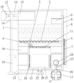
图1为本实用新型的正剖图;Fig. 1 is the front sectional view of the utility model;
图2为本实用新型的图1中A处结构放大图;Fig. 2 is an enlarged view of the structure at place A in Fig. 1 of the present utility model;
图3为本实用新型的收集框和滤网的连接示意图;Fig. 3 is the connection schematic diagram of the collecting frame and the filter screen of the present invention;
图4为本实用新型的转轴和拨动板的连接示意图;Fig. 4 is the connection schematic diagram of the rotating shaft and the toggle plate of the present invention;
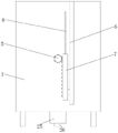
图5为本实用新型的侧视图。Figure 5 is a side view of the utility model.
图中:1、壳体;2、往复丝杆;3、滑块;4、刷板;5、第一齿轮;6、固定板;7、齿板;8、连接线;9、浮块;10、收集框;11、滤网;12、筛筒; 13、进料管;14、联动机构;15、排放机构;16、外框;17、转轴;18、拨动板;19、固定杆;20、连杆;21、U形杆;22、第二齿轮;23、链条;24、刷毛;25、固定框;26、密封管;27、套管;28、套杆;29、浮球;30、堵块;31、挡块。In the figure: 1. Housing; 2. Reciprocating screw; 3. Slider; 4. Brush plate; 5. First gear; 6. Fixed plate; 7. Tooth plate; 8. Connecting wire; 9. Float; 10. Collection frame; 11. Filter screen; 12. Screen cylinder; 13. Feeding pipe; 14. Linkage mechanism; 15. Discharge mechanism; 16. Outer frame; 17. Rotating shaft; 18. Toggle plate; ;20, connecting rod; 21, U-shaped rod; 22, second gear; 23, chain; 24, bristles; 25, fixed frame; 26, sealing tube; 27, sleeve; 28, sleeve rod; 29, float ; 30, block; 31, stop.
具体实施方式Detailed ways
为使本技术领域人员更加清楚和明确本实用新型的技术方案,下面结合实施例及附图对本实用新型作进一步详细的描述,但本实用新型的实施方式不限于此。In order to make the technical solution of the present utility model clearer and clearer to those skilled in the art, the present utility model is described in further detail below with reference to the embodiments and the accompanying drawings, but the embodiments of the present utility model are not limited thereto.
如图1-图5所示,本实施例提供了一种用于工业节水的节能型废水过滤设备,包括壳体1,壳体1的内部转动连接有往复丝杆2,往复丝杆2的外侧滑动连接有滑块3,滑块3的底部固定有刷板4,且刷板4与壳体1的内侧壁滑动连接,往复丝杆2的一端贯穿并延伸至壳体1的外侧,往复丝杆2的一端固定有第一齿轮5,壳体1的一侧固定有固定板6,固定板6的一侧滑动连接有齿板7,且齿板7与第一齿轮5相啮合,齿板7的顶部固定有连接线8,且连接线8的一端贯穿并延伸至壳体1的内部,连接线8的一端固定有浮块9,壳体1的内部对称设置有收集框10,收集框10之间固定有滤网11,壳体1 的内底壁固定有筛筒12,壳体1上设置有进料管13,壳体1上设置有联动机构14,壳体1上设置有排放机构15。As shown in FIGS. 1-5 , this embodiment provides an energy-saving waste water filtration device for industrial water saving, including a
在本实施例中,如图1、4所示,联动机构14包括外框16和连杆20,外框16位于壳体1的一侧,且外框16与进料管13的一端固定连接,外框16 的内部转动连接有转轴17,转轴17的外侧均匀设置有拨动板18,转轴17的底部固定有固定杆19,且固定杆19的底端贯穿并延伸至外框16的底部,连杆20位于筛筒12的底部,且连杆20的顶端贯穿并延伸至筛筒12的内部,连杆20的顶端固定有U形杆21,U形杆21的外侧设置有刷毛24,连杆20的底端贯穿并延伸至壳体1的底部,连杆20的底端和固定杆19的底端皆固定有第二齿轮22,第二齿轮22之间啮合有链条23,废水进入外框16内冲击力推动拨动板18带动转轴17转动,转轴17带动固定杆19以及固定杆19底部的第二齿轮22转动,并通过链条23带动连杆20底部的第二齿轮22转动,第二齿轮22带动连杆20以及U形杆21转动,对筛筒12内壁清理,能够利用水的冲击力连动内部的刷板转动以对过滤桶内壁清理,提高废水的过滤速度,同时进一步提高该设备的节能性。In this embodiment, as shown in FIGS. 1 and 4 , the
在本实施例中,如图1-2所示,排放机构15包括固定框25和套管27,固定框25位于壳体1的底部,固定框25的底部固定有密封管26,套管27位于壳体1的内侧壁,套管27的内侧壁滑动连接有套杆28,套杆28的顶部固定有浮球29,套杆28的底部固定有堵块30,固定框25的内顶壁对称设置有挡块31,当筛筒12周围水位高于套管27的位置,并使得浮球29浮起时,浮球29则带动套杆28以及堵块30上浮,堵块30脱离密封管26内,筛筒12 周围的水通过固定框25和密封管26排出,当水位达到一定的高度过滤后的废水即从底部排出,无需人工调节,便于后期的污水处理,该设备节能环保,给人们的使用提供了便利。In this embodiment, as shown in FIGS. 1-2 , the
在本实施例中,如图1所示,固定杆19的外侧转动连接有限位管,且限位管的一侧通过连接杆与壳体1的一侧固定连接,提高固定杆19的稳定性。In this embodiment, as shown in FIG. 1 , the outer side of the fixing
在本实施例中,如图1所示,浮块9的重量大于齿板7的重量,浮块9 不上浮时,齿板7被浮块9拉动处于高位置,浮块9上浮时便于齿板7向下移动。In this embodiment, as shown in FIG. 1 , the weight of the floating block 9 is greater than the weight of the
在本实施例中,如图1所示,堵块30为圆锥形块,便于堵住密封管26 的入口。In this embodiment, as shown in FIG. 1 , the blocking
如图1-图5所示,本实施例提供了一种用于工业节水的节能型废水过滤设备的工作过程如下:As shown in Figures 1-5, the present embodiment provides an energy-saving wastewater filtration device for industrial water saving. The working process is as follows:
步骤1:滤网11处堵塞时,滤网11顶部积水使得浮块9浮起,浮块9浮起后,浮块9通过连接线8连接的齿板7在重力作用下向下平移,而同时齿板7带动第一齿轮5转动,第一齿轮5则带动往复丝杆2转动,使得滑块3 带动刷板4在滤网11顶部往复移动,将滤网11顶部的固体杂质推动至收集框10内,进而疏通滤网11网面;Step 1: When the
步骤2:废水进入外框16内冲击力推动拨动板18带动转轴17转动,转轴17带动固定杆19以及固定杆19底部的第二齿轮22转动,并通过链条23 带动连杆20底部的第二齿轮22转动,第二齿轮22带动连杆20以及U形杆 21转动,对筛筒12内壁清理;Step 2: The waste water enters the
步骤3:当筛筒12周围水位高于套管27的位置,并使得浮球29浮起,浮球29则带动套杆28以及堵块30上浮,堵块30脱离密封管26内,筛筒12 周围的水通过固定框25和密封管26排出。Step 3: When the water level around the
以上所述,仅为本实用新型进一步的实施例,但本实用新型的保护范围并不局限于此,任何熟悉本技术领域的技术人员在本实用新型所公开的范围内,根据本实用新型的技术方案及其构思加以等同替换或改变,都属于本实用新型的保护范围。The above are only further embodiments of the present utility model, but the protection scope of the present utility model is not limited thereto. Equivalent replacement or modification of the technical solutions and their concepts all belong to the protection scope of the present invention.
Claims (6)
Priority Applications (1)
| Application Number | Priority Date | Filing Date | Title |
|---|---|---|---|
| CN202123231855.XU CN217163338U (en) | 2021-12-21 | 2021-12-21 | Energy-saving type wastewater filtering equipment for industrial water saving |
Applications Claiming Priority (1)
| Application Number | Priority Date | Filing Date | Title |
|---|---|---|---|
| CN202123231855.XU CN217163338U (en) | 2021-12-21 | 2021-12-21 | Energy-saving type wastewater filtering equipment for industrial water saving |
Publications (1)
| Publication Number | Publication Date |
|---|---|
| CN217163338U true CN217163338U (en) | 2022-08-12 |
Family
ID=82713571
Family Applications (1)
| Application Number | Title | Priority Date | Filing Date |
|---|---|---|---|
| CN202123231855.XU Expired - Fee Related CN217163338U (en) | 2021-12-21 | 2021-12-21 | Energy-saving type wastewater filtering equipment for industrial water saving |
Country Status (1)
| Country | Link |
|---|---|
| CN (1) | CN217163338U (en) |
-
2021
- 2021-12-21 CN CN202123231855.XU patent/CN217163338U/en not_active Expired - Fee Related
Similar Documents
| Publication | Publication Date | Title |
|---|---|---|
| CN219231574U (en) | A construction engineering drainage device | |
| CN211189269U (en) | Water treatment facilities convenient to wash filter screen | |
| CN208378456U (en) | Sewage-treatment plant is used in a kind of processing of fabrics printing and dyeing | |
| CN217067859U (en) | Be used for river crab to breed water purification installation | |
| CN219663052U (en) | Sundry filtering device for water environment treatment | |
| CN214415755U (en) | Waste water recovery device used in green building construction | |
| CN215799099U (en) | Concentrated sludge compression dewatering device for sewage treatment | |
| CN221867578U (en) | Sewage treatment sand removal device | |
| CN221692892U (en) | Recoil roller scraper chip removal device | |
| CN221500698U (en) | A garden landscape water circulation purification treatment device | |
| CN219239297U (en) | Rotary fine grid for cyclone grit chamber | |
| CN218653292U (en) | Chemical industry is waste water coarse filtration equipment for environmental protection | |
| CN115304177B (en) | Environment-friendly waste water treatment equipment | |
| CN213623341U (en) | Surface treatment waste water recovery device for cleaner production | |
| CN214075286U (en) | A simple rural sewage treatment device | |
| CN211912909U (en) | An improved sewage treatment system | |
| CN209024304U (en) | An environmentally friendly pig farm sewage collection tank | |
| CN218880775U (en) | A water inlet water purification mechanism for water conservancy projects | |
| CN207959308U (en) | A kind of power station drum-type sewage disposal device for river channel | |
| CN217829035U (en) | Sewage treatment equipment with self-cleaning function | |
| CN211385374U (en) | Spiral Sand Settler | |
| CN218813467U (en) | A water diversion device for water conservancy and hydropower | |
| CN220834411U (en) | Wastewater slag removal mechanism | |
| CN222286505U (en) | A green building sewage treatment device | |
| CN220704473U (en) | Water conservancy river course trash device |
Legal Events
| Date | Code | Title | Description |
|---|---|---|---|
| GR01 | Patent grant | ||
| GR01 | Patent grant | ||
| CF01 | Termination of patent right due to non-payment of annual fee |
Granted publication date: 20220812 |
|
| CF01 | Termination of patent right due to non-payment of annual fee |