CN217151114U - Scaffold capable of transporting materials - Google Patents
Scaffold capable of transporting materials Download PDFInfo
- Publication number
- CN217151114U CN217151114U CN202220001770.8U CN202220001770U CN217151114U CN 217151114 U CN217151114 U CN 217151114U CN 202220001770 U CN202220001770 U CN 202220001770U CN 217151114 U CN217151114 U CN 217151114U
- Authority
- CN
- China
- Prior art keywords
- driving
- bottom side
- groove
- plate
- scaffold
- Prior art date
- Legal status (The legal status is an assumption and is not a legal conclusion. Google has not performed a legal analysis and makes no representation as to the accuracy of the status listed.)
- Active
Links
- 239000000463 material Substances 0.000 title claims abstract description 27
- 238000009434 installation Methods 0.000 claims abstract description 18
- 229910000831 Steel Inorganic materials 0.000 claims description 8
- 230000005540 biological transmission Effects 0.000 claims description 8
- 239000010959 steel Substances 0.000 claims description 8
- 230000007306 turnover Effects 0.000 claims description 3
- 230000001360 synchronised effect Effects 0.000 description 4
- 238000010586 diagram Methods 0.000 description 2
- 239000000203 mixture Substances 0.000 description 2
- 238000012986 modification Methods 0.000 description 2
- 230000004048 modification Effects 0.000 description 2
- 235000017166 Bambusa arundinacea Nutrition 0.000 description 1
- 235000017491 Bambusa tulda Nutrition 0.000 description 1
- 241001330002 Bambuseae Species 0.000 description 1
- 235000015334 Phyllostachys viridis Nutrition 0.000 description 1
- 239000011425 bamboo Substances 0.000 description 1
- 238000010276 construction Methods 0.000 description 1
- 238000005034 decoration Methods 0.000 description 1
- 230000007547 defect Effects 0.000 description 1
- 230000000694 effects Effects 0.000 description 1
- 238000000034 method Methods 0.000 description 1
- 230000002093 peripheral effect Effects 0.000 description 1
- 125000006850 spacer group Chemical group 0.000 description 1
- 229920002994 synthetic fiber Polymers 0.000 description 1
- 239000002023 wood Substances 0.000 description 1
Images


Landscapes
- Conveying And Assembling Of Building Elements In Situ (AREA)
Abstract
The utility model belongs to the technical field of the scaffold frame, especially, be a scaffold frame of transportable material, which comprises a roof, the below of roof is provided with the scaffold frame main part, the installation U-shaped groove has been seted up to the bottom side of roof, fixed mounting has the mounting panel on the lateral wall in U-shaped groove, rotate on the mounting panel and install four supporting lead screws, spout and mounting groove have been seted up to the bottom side of mounting panel, same accommodate the lead screw is installed to spout and mounting groove internal rotation, slidable mounting has the subassembly that lifts by crane in the spout, the bottom side fixed mounting of mounting panel has drive assembly, the dwang is installed in the vertical rotation in the mounting groove. The utility model relates to a rationally, easy operation can realize lifting by crane the transportation perpendicularly and transversely of material as required, is convenient for simultaneously with material handling to the different positions of scaffold frame, and can adjust the height of lifting by crane the subassembly as required, and it is convenient to use.
Description
Technical Field
The utility model relates to a scaffold technical field, in particular to scaffold frame of transportable material.
Background
Scaffolding (scaffold) refers to the various supports erected on a construction site for workers to handle and address vertical and horizontal transport. The general term of the building industry refers to the places which cannot be directly constructed on the building site and are used for exterior wall, interior decoration or high floor height. Mainly for constructors to live up and down or for peripheral safety net enclosure, overhead installation components and the like, the scaffold is said to be made of bamboo, wood, steel pipes or synthetic materials. Some projects also use scaffolds as templates, and in addition, the scaffold is widely used in advertising, municipal administration, traffic roads and bridges, mines and other departments.
However current scaffold frame does not generally possess the function of vertical transport material, need install the hoist engine in the upper strata of scaffold frame in order to realize vertical transport, then lift by crane the transportation to the material, but the mounted position relatively fixed of hoist engine, be not convenient for adjust, only can transport the material to same position, then carry by the manpower, the operation is comparatively loaded down with trivial details, consequently, the utility model provides a scaffold frame that can transport the material is used for solving above-mentioned problem.
SUMMERY OF THE UTILITY MODEL
The utility model aims at solving the defects of the prior art and providing a scaffold capable of transporting materials.
The above technical purpose of the present invention can be achieved by the following technical solutions: a scaffold capable of transporting materials comprises a top plate, a scaffold main body is arranged below the top plate, an installation U-shaped groove is formed in the bottom side of the top plate, an installation plate is fixedly installed on the side wall of the U-shaped groove, four supporting lead screws are rotatably installed on the installation plate, a sliding groove and an installation groove are formed in the bottom side of the installation plate, the same adjusting lead screw is rotatably installed in the sliding groove and the installation groove, a lifting assembly is slidably installed in the sliding groove, a driving assembly is fixedly installed at the bottom side of the installation plate, a rotating rod is vertically and rotatably installed in the installation groove, a driving bevel gear is fixedly sleeved at one end, away from the driving assembly, of the adjusting lead screw, a driven bevel gear and a driving gear are fixedly sleeved on the rotating rod, the driving bevel gear is meshed with the driven bevel gear, and a linkage assembly is arranged on one of the four supporting lead screws, and the four supporting lead screws are all in threaded connection with the standard joints of the scaffold.
Preferably, internal threads are formed in four supporting columns of the standard scaffold joint, and the four supporting screws are respectively installed on the corresponding supporting columns through the internal threads.
Preferably, the lifting assembly comprises a lifting motor and a moving block, the lifting motor is fixedly mounted on the bottom side of the moving block, the moving block is in threaded connection with the adjusting screw rod, a plurality of guide grooves are formed in the inner walls of the front side and the rear side of each sliding groove, limit pins are fixedly mounted on the front side and the rear side of the moving block, the limit pins are respectively in sliding connection with the corresponding guide grooves, a storage roller is fixedly mounted on an output shaft of the lifting motor, a steel wire rope is fixedly wound on the storage roller, and a lifting hook is fixedly mounted at one end, away from the storage roller, of the steel wire rope.
Preferably, the driving assembly comprises an adjusting motor, a driving chain wheel and a driven chain wheel, the adjusting motor is fixedly installed on the bottom side of the mounting plate, the driving chain wheel and the driven chain wheel are fixedly sleeved on an output shaft of the adjusting motor and an adjusting screw rod respectively, and the driving chain wheel and the driven chain wheel are in transmission connection with the same transmission chain.
Preferably, the linkage subassembly includes square plate, sliding sleeve and driven gear, and sliding sleeve slidable mounting is in the outside of supporting the lead screw, and the sliding sleeve rotates to be installed on the square plate, and the fixed cover of driven gear is established in the outside of sliding sleeve, and driven gear meshes with the driving gear mutually.
Preferably, a plurality of guide bars are fixedly mounted on the inner wall of the sliding sleeve, a plurality of strip-shaped grooves are formed in one of the four support screws, and the plurality of guide bars are respectively slidably mounted in the corresponding strip-shaped grooves.
Preferably, four support lead screws are all fixedly sleeved with a linkage chain wheel, and the four linkage chain wheels are in transmission connection with the same linkage chain.
Preferably, an electric push rod is fixedly mounted on the bottom side of the mounting plate, and one end, far away from the mounting plate, of the electric push rod is fixedly mounted on the turnover plate.
The utility model has the advantages that: the utility model discloses in, through accommodate motor, drive sprocket, accommodate lead screw can be controlled to rotate under driven sprocket and drive chain's the cooperation, thereby can control the movable block and carry out position control along the spout, can make the motion that the movable block remains stable under the cooperation of guide way and spacer pin simultaneously, through lifting by crane the motor, accomodate the roller, can lift by crane the transportation to the material under the effect of wire rope and lifting hook, promote the square board through electric putter and make the sliding sleeve slide along supporting lead screw, thereby can control driven gear and driving gear entering engaged state, support post and supporting lead screw's cooperation can be controlled mounting panel and roof and go up and down on scaffold frame standard festival, thereby be convenient for adjust the height that lifts by crane the subassembly as required.
Drawings
In order to more clearly illustrate the technical solutions in the embodiments of the present invention, the drawings needed to be used in the description of the embodiments will be briefly described below, and it is obvious that the drawings in the following description are only some embodiments of the present invention, and it is obvious for those skilled in the art to obtain other drawings without creative efforts.
Fig. 1 is a schematic perspective view of a scaffold capable of transporting materials according to the present invention;
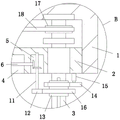
fig. 2 is a schematic partial sectional structural view of a scaffold capable of transporting materials according to the present invention;
fig. 3 is a schematic structural diagram of a part a of the scaffold capable of transporting materials according to the present invention;
fig. 4 is a schematic structural diagram of a part B of the scaffold capable of transporting materials according to the present invention;
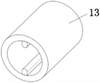
fig. 5 is a schematic structural view of the sliding sleeve provided by the present invention.
In the figure: 1. a top plate; 2. mounting a plate; 3. a support lead screw; 4. a chute; 5. mounting grooves; 6. adjusting a screw rod; 7. a driven sprocket; 8. adjusting the motor; 9. a drive sprocket; 10. a drive chain; 11. rotating the rod; 12. a driving gear; 13. a sliding sleeve; 14. a square plate; 15. an electric push rod; 16. a driven gear; 17. a link sprocket; 18. a linkage chain; 19. a moving block; 20. and (5) hoisting the motor.
Detailed Description
The technical solution of the present invention will be clearly and completely described below with reference to the specific embodiments. It is obvious that the described embodiments are only some of the embodiments of the present invention, and not all of them. Based on the embodiments of the present invention, all other embodiments obtained by a person of ordinary skill in the art without creative efforts belong to the protection scope of the present invention.
The first embodiment is as follows: referring to fig. 1-5, a scaffold capable of transporting materials comprises a top plate 1, a scaffold main body is arranged below the top plate 1, a mounting U-shaped groove is arranged at the bottom side of the top plate 1, a mounting plate 2 is fixedly mounted on the side wall of the U-shaped groove, four supporting screws 3 are rotatably mounted on the mounting plate 2, a chute 4 and a mounting groove 5 are arranged at the bottom side of the mounting plate 2, the same adjusting screw 6 is rotatably mounted in the chute 4 and the mounting groove 5, a hoisting component is slidably mounted in the chute 4, a driving component is fixedly mounted at the bottom side of the mounting plate 2, a rotating rod 11 is vertically and rotatably mounted in the mounting groove 5, a driving bevel gear is fixedly sleeved at one end of the adjusting screw 6 far away from the driving component, a driven bevel gear and a driving gear 12 are fixedly sleeved on the rotating rod 11, the driving bevel gear is meshed with the driven bevel gear, and a linkage component is arranged on one supporting screw 3 of the four supporting screws 3, and the four supporting screw rods 3 are all in threaded connection with the standard joints of the scaffold.
In this embodiment, all set up the internal thread on four support columns of scaffold frame standard festival, four support screw 3 are installed on the support column that corresponds through the internal thread screw respectively, can provide the support to four support screw 3 through four support columns of scaffold frame standard festival, are convenient for carry out lifting operation simultaneously.
In this embodiment, the lifting component includes a lifting motor 20 and a moving block 19, the lifting motor 20 is fixedly mounted on the bottom side of the moving block 19, the moving block 19 is in threaded connection with the adjusting screw rod 6, a plurality of guide grooves are formed in the inner walls of the front side and the rear side of the sliding groove 4, limit pins are fixedly mounted on the front side and the rear side of the moving block 19, the limit pins are respectively in sliding connection with the corresponding guide grooves, a containing roller is fixedly mounted on an output shaft of the lifting motor 20, a steel wire rope is fixedly wound on the containing roller, a lifting hook is fixedly mounted at one end, far away from the containing roller, of the steel wire rope, the lifting component can lift cargoes, the moving block 19 can be controlled to slide along the sliding groove 4 when the adjusting screw rod 6 rotates, and the moving block 19 can be kept good stability when sliding along the sliding groove 4 under the cooperation of the guide grooves and the limit pins.
In this embodiment, drive assembly includes accommodate motor 8, drive sprocket 9 and driven sprocket 7, accommodate motor 8 fixed mounting is in the bottom side of mounting panel 2, drive sprocket 9 and driven sprocket 7 are fixed the cover respectively and are established on accommodate motor 8's output shaft and accommodate the lead screw 6, and drive connection has same drive chain 10 on drive sprocket 9 and the driven sprocket 7, can control accommodate the lead screw 6 through drive assembly as required and rotate, thereby be convenient for adjust the position of lifting by crane the subassembly.
In this embodiment, the linkage subassembly includes square plate 14, sliding sleeve 13 and driven gear 16, and sliding sleeve 13 slidable mounting is in the outside of supporting lead screw 3, and sliding sleeve 13 rotates and installs on square plate 14, and the fixed cover of driven gear 16 is established in the outside of sliding sleeve 13, and driven gear 16 meshes with driving gear 12 mutually, can control supporting lead screw 3 and rotate when dwang 11 rotates through the linkage subassembly.
In this embodiment, fixed mounting has a plurality of gibs on the inner wall of sliding sleeve 13, has seted up a plurality of bar grooves on the support lead screw 3 of four support lead screws 3, and a plurality of gibs are slidable mounting respectively in the bar inslot that corresponds, can make sliding sleeve 13 follow support lead screw 3 and keep stable slip through the cooperation in gib block and bar groove down, can drive sliding sleeve 13 synchronous rotation when support lead screw 3 rotates simultaneously.
In this embodiment, the four support screws 3 are all fixedly sleeved with the linkage chain wheels 17, the four linkage chain wheels 17 are in transmission connection with the same linkage chain 18, and the four support screws 3 can be kept in synchronous rotation through the cooperation of the linkage chain wheels 17 and the linkage chain 18.
In this embodiment, an electric push rod 15 is fixedly mounted on the bottom side of the mounting plate 2, one end of the electric push rod 15, which is far away from the mounting plate 2, is fixedly mounted on the turnover plate 14, and the electric push rod 15 can control the square plate 14 to perform lifting operation, so that the connection state of the driven gear 16 and the driving gear 12 can be controlled.
The scaffold standard knot comprises four support columns, a springboard, a cross brace, a support rod and a connecting piece, and the combination mode of the scaffold standard knot is common in the technical field and belongs to the prior art, so that the combination mode is not described in detail herein.
The working principle is as follows: when the lifting device is used, firstly, the power supply is switched on, when goods need to be lifted and transported, the adjusting screw rod 6 is controlled to rotate under the coordination of the adjusting motor 8, the driving chain wheel 9, the driven chain wheel 7 and the transmission chain 10, so that the moving block 19 can be controlled to be adjusted to a proper position along the sliding chute 4, meanwhile, the moving block 19 can keep stable sliding along the sliding chute 4 under the coordination of a plurality of guide grooves and limiting pins, the rotating rod 11 can be driven to rotate the driving gear 12 under the coordination of the driving bevel gear and the driven bevel gear while the adjusting screw rod 6 rotates, the steel wire rope is paid off by driving the accommodating roller through the lifting motor 20, so that the lifting hook can be put down, the goods can be lifted and transported through the lifting hook, the lifted goods can be lifted to different positions of the springboard as required under the coordination of the adjusting motor 8, the adjusting screw rod 6 and other components, when the height of the lifting motor 20 needs to be adjusted, promote square plate 14 through electric putter 15 and make sliding sleeve 13 drive driven gear 16 and driving gear 12 and get into the engaged state, can make sliding sleeve 13 keep stable slip along supporting lead screw 3 under the cooperation of bar groove and gib block, can drive supporting lead screw 3 simultaneously and rotate, can make four supporting lead screws 3 keep synchronous rotation under the cooperation of linkage sprocket 17 and linkage chain 18 to can control roof 1 and carry out altitude mixture control.
Example two: the difference between the second embodiment and the first embodiment is that, referring to fig. 2 and 4, four support screws 3 are rotatably connected to the top ends of the corresponding scaffold support columns, the mounting plate 2 is slidably connected to the side walls of the U-shaped groove, and the four supporting screw rods 3 are all in threaded connection with the mounting plate 2, the four supporting screw rods 3 are all fixedly sleeved with limiting rings, and the four limiting rings are positioned on the same horizontal plane, when the square plate 14 is pushed by the electric push rod 15 to make the sliding sleeve 13 drive the driven gear 16 and the driving gear 12 to enter a meshing state, the driving gear 12 drives the sliding sleeve 13 to rotate through the driven gear 16, can make sliding sleeve 13 drive support screw 3 and rotate under the cooperation in bar groove and gib block, make square plate 14 drive sliding sleeve 13 and mounting panel 2 keep synchronous motion simultaneously under the cooperation in gib block and bar groove, highly realizing lifting by crane the altitude mixture control of subassembly through adjustment mounting panel 2.
The scaffold capable of transporting materials provided by the present invention has been described in detail above. The principles and embodiments of the present invention have been explained herein using specific embodiments, which are merely used to help understand the method and its core ideas of the present invention. It should be noted that, for those skilled in the art, without departing from the principle of the present invention, the present invention can be further modified and modified, and such modifications and modifications also fall within the protection scope of the appended claims.
Claims (8)
1. A scaffold capable of transporting materials comprises a top plate (1) and is characterized in that a scaffold main body is arranged below the top plate (1), an installation U-shaped groove is formed in the bottom side of the top plate (1), an installation plate (2) is fixedly installed on the side wall of the U-shaped groove, four support lead screws (3) are rotatably installed on the installation plate (2), a sliding groove (4) and an installation groove (5) are formed in the bottom side of the installation plate (2), the same adjusting lead screw (6) is rotatably installed in the sliding groove (4) and the installation groove (5), a lifting assembly is slidably installed in the sliding groove (4), a driving assembly is fixedly installed on the bottom side of the installation plate (2), a rotating rod (11) is vertically rotatably installed in the installation groove (5), and a driving bevel gear is fixedly installed at one end, away from the driving assembly, of the adjusting lead screw (6), fixed cover is equipped with driven bevel gear and driving gear (12) on dwang (11), and driving bevel gear and driven bevel gear mesh mutually, is provided with the linkage subassembly on one support lead screw (3) in four support lead screw (3), and four support lead screws (3) all with scaffold frame standard festival threaded connection.
2. A material transportable scaffolding as claimed in claim 1, wherein: internal threads are formed in four supporting columns of the standard joint of the scaffold, and the four supporting lead screws (3) are installed on the corresponding supporting columns through the internal threads respectively.
3. A material transportable scaffolding as claimed in claim 1, wherein: the lifting assembly comprises a lifting motor (20) and a moving block (19), the lifting motor (20) is fixedly installed on the bottom side of the moving block (19), the moving block (19) is in threaded connection with an adjusting screw rod (6), a plurality of guide grooves are formed in the inner walls of the front side and the rear side of a sliding groove (4), limiting pins are fixedly installed on the front side and the rear side of the moving block (19), the limiting pins are respectively in sliding connection with the corresponding guide grooves, a containing roller is fixedly installed on an output shaft of the lifting motor (20), a steel wire rope is fixedly wound on the containing roller in a parallel mode, and a lifting hook is fixedly installed at one end, far away from the containing roller, of the steel wire rope.
4. A material transportable scaffolding as claimed in claim 1, wherein: the driving assembly comprises an adjusting motor (8), a driving chain wheel (9) and a driven chain wheel (7), the adjusting motor (8) is fixedly installed on the bottom side of the mounting plate (2), the driving chain wheel (9) and the driven chain wheel (7) are fixedly sleeved on an output shaft of the adjusting motor (8) and an adjusting screw rod (6) respectively, and the driving chain wheel (9) and the driven chain wheel (7) are in transmission connection with a same transmission chain (10).
5. A material transportable scaffolding as claimed in claim 1, wherein: the linkage assembly comprises a square plate (14), a sliding sleeve (13) and a driven gear (16), the sliding sleeve (13) is slidably mounted on the outer side of the support screw rod (3), the sliding sleeve (13) is rotatably mounted on the square plate (14), the driven gear (16) is fixedly sleeved on the outer side of the sliding sleeve (13), and the driven gear (16) is meshed with the driving gear (12).
6. A material transportable scaffolding as claimed in claim 5, wherein: a plurality of guide strips are fixedly mounted on the inner wall of the sliding sleeve (13), a plurality of strip-shaped grooves are formed in one support lead screw (3) of the four support lead screws (3), and the guide strips are respectively slidably mounted in the corresponding strip-shaped grooves.
7. A material transportable scaffolding as claimed in claim 1, wherein: the four supporting screw rods (3) are fixedly sleeved with linkage chain wheels (17), and the four linkage chain wheels (17) are in transmission connection with the same linkage chain (18).
8. A material transportable scaffolding as claimed in claim 5, wherein: the bottom side of the mounting plate (2) is fixedly provided with an electric push rod (15), and one end, far away from the mounting plate (2), of the electric push rod (15) is fixedly arranged on the turnover plate (14).
Priority Applications (1)
| Application Number | Priority Date | Filing Date | Title |
|---|---|---|---|
| CN202220001770.8U CN217151114U (en) | 2022-01-04 | 2022-01-04 | Scaffold capable of transporting materials |
Applications Claiming Priority (1)
| Application Number | Priority Date | Filing Date | Title |
|---|---|---|---|
| CN202220001770.8U CN217151114U (en) | 2022-01-04 | 2022-01-04 | Scaffold capable of transporting materials |
Publications (1)
| Publication Number | Publication Date |
|---|---|
| CN217151114U true CN217151114U (en) | 2022-08-09 |
Family
ID=82689652
Family Applications (1)
| Application Number | Title | Priority Date | Filing Date |
|---|---|---|---|
| CN202220001770.8U Active CN217151114U (en) | 2022-01-04 | 2022-01-04 | Scaffold capable of transporting materials |
Country Status (1)
| Country | Link |
|---|---|
| CN (1) | CN217151114U (en) |
-
2022
- 2022-01-04 CN CN202220001770.8U patent/CN217151114U/en active Active
Similar Documents
| Publication | Publication Date | Title |
|---|---|---|
| CN210457317U (en) | Vertical transport vechicle is built in room | |
| CN210768826U (en) | Tunnel concrete lining platform truck end steel form mechanism | |
| CN111606244A (en) | Assembled building element hoist device | |
| CN211285297U (en) | Bridge engineering is with folding construction support of safe type | |
| CN218754507U (en) | Railway T beam bridge crane hoist and mount auxiliary device | |
| CN214220540U (en) | Steel structure construction system | |
| CN211078283U (en) | Liftable support for construction engineering construction | |
| CN211419394U (en) | Hoisting device for steel structure building construction | |
| CN221546427U (en) | Be used for building engineering platform of unloading | |
| CN209799413U (en) | A safe unloading platform | |
| CN219175790U (en) | Light steel member construction platform for building | |
| CN215665954U (en) | Robot stacking device | |
| CN213171212U (en) | A hoisting apparatus for building engineering | |
| CN214031459U (en) | Building engineering material lifting machine | |
| JPH0319567Y2 (en) | ||
| CN203295074U (en) | Telescopic two-dimensional full-automatic miniature cantilever crane | |
| CN114560416A (en) | Vertical transportation equipment for prefabricated building | |
| CN114541731A (en) | Novel wall body adheres to and promotes construction platform | |
| CN221587837U (en) | Construction hanger for building engineering | |
| CN221235113U (en) | Portal frame for vertical transportation in house construction | |
| CN223018209U (en) | Steel construction factory building roofing bottom plate is hung construction platform against | |
| CN220666841U (en) | Bearing frame for building construction | |
| CN222593394U (en) | A transport device for finished steel strand coils | |
| CN222893944U (en) | Working platform for masonry wall | |
| CN211895824U (en) | Crane for small-sized engineering construction |
Legal Events
| Date | Code | Title | Description |
|---|---|---|---|
| GR01 | Patent grant | ||
| GR01 | Patent grant |