CN217148894U - High concentration pharmaceutical factory effluent treatment plant - Google Patents
High concentration pharmaceutical factory effluent treatment plant Download PDFInfo
- Publication number
- CN217148894U CN217148894U CN202123419434.XU CN202123419434U CN217148894U CN 217148894 U CN217148894 U CN 217148894U CN 202123419434 U CN202123419434 U CN 202123419434U CN 217148894 U CN217148894 U CN 217148894U
- Authority
- CN
- China
- Prior art keywords
- tank
- sludge
- water
- secondary sedimentation
- anoxic
- Prior art date
- Legal status (The legal status is an assumption and is not a legal conclusion. Google has not performed a legal analysis and makes no representation as to the accuracy of the status listed.)
- Active
Links
Images
Classifications
-
- Y—GENERAL TAGGING OF NEW TECHNOLOGICAL DEVELOPMENTS; GENERAL TAGGING OF CROSS-SECTIONAL TECHNOLOGIES SPANNING OVER SEVERAL SECTIONS OF THE IPC; TECHNICAL SUBJECTS COVERED BY FORMER USPC CROSS-REFERENCE ART COLLECTIONS [XRACs] AND DIGESTS
- Y02—TECHNOLOGIES OR APPLICATIONS FOR MITIGATION OR ADAPTATION AGAINST CLIMATE CHANGE
- Y02E—REDUCTION OF GREENHOUSE GAS [GHG] EMISSIONS, RELATED TO ENERGY GENERATION, TRANSMISSION OR DISTRIBUTION
- Y02E50/00—Technologies for the production of fuel of non-fossil origin
- Y02E50/30—Fuel from waste, e.g. synthetic alcohol or diesel
Landscapes
- Physical Water Treatments (AREA)
Abstract
The utility model discloses a high-concentration pharmaceutical factory wastewater treatment device, which comprises a pretreatment unit, a high-efficiency air flotation device, an intermediate water tank, a UASB anaerobic reactor, an A/O process tank, a secondary sedimentation tank and a sludge treatment system; the pretreatment unit comprises a grating water collecting well and a regulating tank; the A/O process pool comprises an anoxic pool and a biological contact oxidation pool; the grid water collecting well, the adjusting tank, the efficient air floatation device, the intermediate water tank, the UASB anaerobic reactor, the anoxic tank, the biological contact oxidation tank and the secondary sedimentation tank are sequentially connected; a sludge return pipe for returning sludge is arranged between the anoxic tank and the secondary sedimentation tank; a mixed liquid backflow pipeline is also arranged between the anoxic tank and the biological contact oxidation tank; the secondary sedimentation tank is communicated with a sludge treatment system. The utility model provides a pharmacy industrial waste water pollutes greatly, difficult processing etc. not enough, through optimizing anaerobic fermentation efficiency, reduces its processing cost simultaneously, guarantees that waste water treatment stabilizes discharge to reach standard, produces the marsh gas recovery energy.
Description
Technical Field
The utility model relates to a pharmaceutical factory waste water treatment technical field, more specifically relates to a high concentration pharmaceutical factory effluent treatment plant.
Background
In recent years, diseases are in a high-incidence trend due to the influence of a plurality of factors, and the demand of therapeutic drugs, health care drugs and vaccines is increasing, which greatly promotes the development of biological pharmaceutical factories, but simultaneously generates a large amount of pharmaceutical wastewater. The pharmaceutical factory wastewater mainly comprises waste filtrate, solvent recovery raffinate and waste mother liquor, and the wastewater contains high-concentration pollutants, has large changes of acidity and alkalinity and water temperature, and has large wastewater treatment difficulty. At present, biological treatment technology (anaerobic, aerobic, anaerobic and aerobic), physicochemical treatment technology and chemical treatment technology are mainly used for treatment. How to select a high-efficiency, low-cost and stable up-to-standard process technical route and a device, and realizing clean production is the research and development trend of sewage treatment technology.
Disclosure of Invention
The utility model aims to solve pharmaceutical industry waste water and pollute not enough such as big, the difficult processing, simultaneously through optimizing anaerobic fermentation efficiency, improve the treatment effeciency, reduce its processing cost, guarantee that waste water treatment stabilizes discharge to reach standard, produce the marsh gas recovery energy, reach energy-conserving carbon reduction purpose.
In order to solve the problems, the high-concentration pharmaceutical factory wastewater treatment device comprises a pretreatment unit, a high-efficiency air flotation device, an intermediate water tank, a UASB anaerobic reactor, an A/O process tank, a secondary sedimentation tank and a sludge treatment system; the pretreatment unit comprises a grating water collecting well and a regulating tank; the A/O process pool comprises an anoxic pool and a biological contact oxidation pool; the grid water collecting well, the adjusting tank, the efficient air floatation device, the intermediate water tank, the UASB anaerobic reactor, the anoxic tank, the biological contact oxidation tank and the secondary sedimentation tank are sequentially connected; a sludge return pipe for returning sludge is arranged between the anoxic tank and the secondary sedimentation tank; a mixed liquid backflow pipeline is also arranged between the anoxic tank and the biological contact oxidation tank; the secondary sedimentation tank is communicated with a sludge treatment system.
In particular, the grid water collecting well comprises a water collecting well, a grid and a lift pump 1 #; the grating is arranged at the front end of the water channel entering the water collecting well; the grid sump pit passes through elevator pump 1# and links to each other with the equalizing basin.
Particularly, a lift pump 2#, a liquid caustic soda feeding device and a nutrient salt feeding device are arranged in the regulating tank; the adjusting tank is communicated with the high-efficiency air flotation device through a lifting pump 2 #.
Particularly, a PAC adding device and a PAM adding device are matched and sleeved in the high-efficiency air floatation device; the lower part of the high-efficiency air flotation device is communicated with the upper part of the middle water pool.
Particularly, the middle water tank is provided with a submersible stirrer, and the high-efficiency air floatation machine is erected on the middle water tank; and a lifting pump 3# is arranged between the intermediate water tank and the UASB anaerobic reactor.
Particularly, the UASB anaerobic reactor comprises a tank body, a three-phase separator, a water distribution system, a sludge discharge system, a methane collection tank, a water seal tank and a PH online detector; and the effluent from the top of the UASB anaerobic reactor is communicated with the upper part of the A/O process tank, and the upper part of the A/O process tank is communicated with the lower part of the secondary sedimentation tank.
In particular, the biological contact oxidation tank is provided with a filler, an aeration disc, an aeration pipe, a mixed liquid reflux pump, a Roots blower and an automatic control system. The mixed liquid reflux pump is used for refluxing the mixed liquid of the biological contact oxidation tank and the wastewater to the anoxic tank.
Particularly, the secondary sedimentation tank is matched with a sludge return pump which is used for returning sludge to the anoxic tank through a sludge return pipe.
Particularly, the sludge treatment system comprises a sludge concentration tank and a sludge dewatering machine, and the sludge concentration tank is communicated with the sludge dewatering machine; the secondary sedimentation tank is communicated with the sludge concentration tank; the sludge treatment system is also provided with a sludge inlet pump, a sludge PAM adding device, a pipeline mixer and a filter press.
The working principle of the utility model is as follows:
the utility model discloses set up the pretreatment unit and be used for collecting pharmaceutical factory waste water and carry out the preliminary treatment to pharmaceutical factory waste water. The waste water of the pharmaceutical factory firstly intercepts larger particle suspended matters, floating matters and the like in the waste water through the grids of the grid water collecting well, the waste water passing through the grids flows into the regulating tank, and liquid caustic soda and nutrient salt can be added into the regulating tank through a liquid caustic soda adding device and a nutrient salt adding device, so that the effects of balancing water quantity and water quality are achieved for the waste water.
The utility model is provided with a high-efficiency air flotation device for carrying out air flotation treatment on the pharmaceutical factory wastewater and removing generated suspended matters; tiny suspended particles in the tiny bubbles and the wastewater are adhered to form a bubble particle complex body with the whole density smaller than that of the water, the suspended particles float to the water surface along with the bubbles, then scum can be scraped to a scum discharging groove at regular time through a scum scraping machine, and the scum discharging groove can input the scum into a sludge treatment system for further treatment. After air floatation treatment, suspended matters in the wastewater are greatly reduced, and COD and pH of inlet water are stabilized.
The utility model discloses set up middle pond and be used for collecting the pharmaceutical factory waste water of handling through high-efficient air supporting ware, adjust PH, temperature simultaneously, obtain the waste water that reaches UASB anaerobic reactor entering quality of water condition.
The utility model discloses set up UASB anaerobic reactor and be used for producing marsh gas with the waste water in middle pond under anaerobic condition. Pumping the wastewater in the intermediate pool into a UASB anaerobic reactor, so that the wastewater uniformly enters from the bottom of the UASB anaerobic reactor and upwards passes through an anaerobic sludge bed of the UASB anaerobic reactor; the wastewater is fully contacted with granular sludge or flocculent sludge to generate anaerobic reaction, and methane (mainly CH) is generated under the anaerobic state 4 And CO 2 ). The upward flow of wastewater and the rising of the large amount of generated biogas have a negative impact on the particle contamination in the reactorThe mud has a good natural stirring effect, internal circulation of the mud is caused, a part of the mud moves upwards, and a relatively thin mud suspension layer is formed above a mud bed. After wastewater containing granular sludge enters a separation zone of the UASB anaerobic reactor, bubbles and free bubbles attached to the granular sludge impact the bottom of a gas reflecting plate of a three-phase separator in the separation zone, are separated from the sludge and the wastewater, and are collected in a gas collection chamber of the top three-phase separator of the UASB anaerobic reactor; the granular sludge after releasing the bubbles is precipitated on the surface of a sludge layer under the action of gravity and returns to the reaction zone; the liquid flows out of the UASB anaerobic reactor through the effluent weir. The UASB anaerobic reactor is provided with a sludge discharge pump, and when the sludge is excessive, the UASB anaerobic reactor is discharged to a sludge treatment system.
The utility model is provided with an A/O process pool which comprises an anoxic pool and a biological contact oxidation pool. The wastewater of the UASB anaerobic reactor flows into the anoxic tank, is mixed with anaerobic activated sludge in the anoxic tank and then is contacted with the anaerobic activated sludge, most organic pollutants in the wastewater are converted into micromolecule substances easy to biodegrade through the adsorption, absorption and biodegradation of anaerobic microorganisms, and meanwhile, ammonia nitrogen in the wastewater is removed through denitrification. The wastewater flows into a biological contact oxidation pond for aerobic biodegradation after anaerobic treatment. The biological contact oxidation pond is internally provided with a filler, the aerated and oxygenated sewage is contacted with the filler full of the biological membrane, and the organic matters (pollutants) in the water are assimilated and decomposed under the action of the biological membrane and the aerobic condition to generate CO 2 And H 2 And O. Through aeration and oxygenation, organic matters in water are flocculated, oxidized and decomposed by aerobic microorganisms and then enter a secondary sedimentation tank.
The utility model discloses set up two heavy ponds and be arranged in receiving the biological contact oxidation pond through aerobic reaction's sewage and carry out mud-water separation, the supernatant flows in the air supporting pond further processing, and the mud of production flows back to the oxygen deficiency pond, and surplus sludge is arranged to sludge treatment system.
The utility model discloses set up sludge treatment system sludge thickening tank, sludge dewaterer. The sludge concentration tank can receive scum from the high-efficiency air flotation device, excess sludge from the UASB anaerobic reactor and excess sludge from the secondary sedimentation tank, and the scum is dewatered by the sludge dewatering machine and transported outside.
The utility model discloses following beneficial effect has:
1. the utility model discloses a set up high-efficient air supporting device, get rid of the light suspended solid of proportion, especially lignin etc to reduce the suspended solid and get into follow-up biochemical system, influence its effective dwell time.
2. The utility model discloses an anaerobism goes out the water reflux to middle pond, reduces and throws the liquid caustic soda, the running cost that significantly reduces.
3. The utility model discloses a UASB anaerobic reactor, no mixed agitated vessel in the UASB anaerobic reactor leans on the rising motion of the marsh gas that produces among the fermentation process, makes the mud on sludge blanket upper portion be in the suspended state, also has the stirring of certain degree to the sludge blanket of lower part, can also produce marsh gas recycle simultaneously.
4. The utility model discloses a pollutant such as organic matter and total phosphorus, total nitrogen can be got rid of to the AO technology, utilizes the continuous metabolic decomposition of microorganism and regeneration capacity, only needs through aeration, control good reflux ratio, reduces secondary pollution, is the most ecological environmental protection processing method.
5. The utility model discloses to pharmaceutical factory waste water organic pollution concentration height, suspension height, the higher quality of water of colourity are comparatively complicated to and waste water intermittent type discharges characteristics, adopt the processing technology of "grid equalizing basin + air supporting + UASB anaerobic fermentation + AO technology + secondary sedimentation", get rid of aquatic organic matter, ammonia nitrogen, phosphorus etc. finally discharge to reach standard. The utility model is suitable for a pharmaceutical industry majority waste water, especially high concentration, the organic waste water of difficult degradation, it has that the treatment effect is obvious, economize and account for the land, the operation is stable, advantage such as with low costs, is applicable to the high concentration organic waste water treatment of large, medium and small pharmaceutical factory.
Drawings
In order to more clearly illustrate the embodiments of the present invention or the technical solutions in the prior art, the drawings used in the description of the embodiments or the prior art will be briefly described below, it is obvious that the drawings in the description below are only some embodiments of the present invention, and for those skilled in the art, other drawings can be obtained according to the drawings without creative efforts.
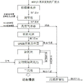
Fig. 1 is an overall structure diagram of the embodiment of the present invention.
Detailed Description
The preferred embodiments of the present invention will be described in detail below with reference to the accompanying drawings, so that the advantages and features of the present invention can be more easily understood by those skilled in the art, and the scope of the present invention can be more clearly and clearly defined.
It should be noted that: like reference numbers and letters refer to like items in the following figures, and thus, once an item is defined in one figure, it need not be further defined and explained in subsequent figures.
It should be noted that the terms "center", "upper", "lower", "left", "right", "vertical", "horizontal", "inner", "outer", and the like refer to the orientation or positional relationship shown in the drawings, or the orientation or positional relationship that the utility model is usually placed when in use, and are used for convenience of description and simplification of description, but do not refer to or imply that the device or element referred to must have a specific orientation, be constructed and operated in a specific orientation, and thus, should not be construed as limiting the present invention. Furthermore, the terms "first," "second," "third," and the like are used solely to distinguish one from another and are not to be construed as indicating or implying relative importance.
Furthermore, the terms "horizontal", "vertical", "overhang" and the like do not imply that the components are required to be absolutely horizontal or overhang, but may be slightly inclined. For example, "horizontal" merely means that the direction is more horizontal than "vertical" and does not mean that the structure must be perfectly horizontal, but may be slightly inclined.
In the description of the present invention, it should also be noted that, unless otherwise explicitly specified or limited, the terms "disposed," "mounted," "connected," and "connected" are to be construed broadly, e.g., as meaning either a fixed connection, a removable connection, or an integral connection; can be mechanically or electrically connected; they may be connected directly or indirectly through intervening media, or they may be interconnected between two elements. The specific meaning of the above terms in the present invention can be understood in specific cases to those skilled in the art.
As shown in FIG. 1, the wastewater treatment device for high concentration pharmaceutical factory of this embodiment comprises a pretreatment unit, an efficient air flotation device, an intermediate water tank, a UASB anaerobic reactor, an A/O process tank, a secondary sedimentation tank and a sludge treatment system. The pretreatment unit comprises a grating water collecting well and a regulating tank. The A/O process pool comprises an anoxic pool and a biological contact oxidation pool. The grid water collecting well, the adjusting tank, the high-efficiency air flotation device, the intermediate water tank, the UASB anaerobic reactor, the anoxic tank, the biological contact oxidation tank and the secondary sedimentation tank are sequentially connected. A sludge return pipe for returning sludge is arranged between the anoxic tank and the secondary sedimentation tank. A mixed liquid backflow pipeline is also arranged between the anoxic tank and the biological contact oxidation tank. The secondary sedimentation tank is communicated with a sludge treatment system.
In the pretreatment unit, the grid water collecting well comprises a water collecting well, a grid and a lifting pump 1 #. The grid is mounted at the front end of the canal into the sump well. The grid sump pit is connected with the equalizing basin through elevator pump 1 #. The regulating tank is internally provided with a lift pump 2#, a liquid caustic soda feeding device and a nutrient salt feeding device. The adjusting tank is communicated with the high-efficiency air flotation device through a lift pump 2 #.
The efficient air floatation device is internally provided with a PAC adding device and a PAM adding device. The lower part of the high-efficiency air floatation device is communicated with the upper part of the middle water pool.
The middle water tank is provided with a submersible stirrer, and the high-efficiency air floatation machine is erected on the middle water tank; and a lifting pump 3# is arranged between the intermediate water tank and the UASB anaerobic reactor.
The UASB anaerobic reactor comprises a tank body, a three-phase separator, a water distribution system, a sludge discharge system, a methane collection tank, a water seal tank and a PH online detector; and the effluent from the top of the UASB anaerobic reactor is communicated with the upper part of the A/O process tank, and the upper part of the A/O process tank is communicated with the lower part of the secondary sedimentation tank.
The biological contact oxidation tank is provided with a filler, an aeration disc, an aeration pipe, a mixed liquid reflux pump, a Roots blower and an automatic control system. The mixed liquid reflux pump is used for refluxing the mixed liquid of the biological contact oxidation tank and the wastewater to the anoxic tank.
The secondary sedimentation tank is matched with a sludge return pump which is used for returning the sludge to the anoxic tank through a sludge return pipe.
The sludge treatment system comprises a sludge concentration tank and a sludge dewatering machine, and the sludge concentration tank is communicated with the sludge dewatering machine; the secondary sedimentation tank is communicated with the sludge concentration tank. The sludge treatment system is also provided with a sludge inlet pump, a sludge PAM adding device, a pipeline mixer and a filter press.
The embodiment of the utility model provides a theory of operation and application method:
firstly, intercepting larger suspended matters, floating matters and the like in the wastewater of a pharmaceutical factory through a grid of a grid water collecting well, enabling the wastewater passing through the grid to flow into a regulating tank, and adding liquid caustic soda and nutrient salt into the regulating tank through a liquid caustic soda adding device and a nutrient salt adding device to balance the water quantity and the water quality of the wastewater.
And step two, the high-efficiency air floatation device is used for carrying out air floatation treatment on the pharmaceutical factory wastewater and removing generated suspended matters. Tiny bubble through in the high-efficient air supporting ware adheres with tiny suspended particle in the waste water mutually, forms the bubble granule complex body that whole density is less than water, and suspended particle floats to the surface of water along with the bubble together, then the accessible scrapes the sediment machine regularly with the dross and scrapes the scum to the scum groove, and the scum groove can be imported the dross to sludge treatment system and carry out further processing. After air floatation treatment, suspended matters in the wastewater are greatly reduced, and COD and pH of inlet water are stabilized.
And step three, collecting the pharmaceutical factory wastewater treated by the high-efficiency air floatation device by the intermediate water tank, and simultaneously adjusting the pH and the temperature to obtain the wastewater which reaches the water quality condition of the UASB anaerobic reactor.
And step four, the UASB anaerobic reactor generates methane from the wastewater in the intermediate pool in an anaerobic state. Pumping the wastewater in the intermediate pool into a UASB anaerobic reactor, so that the wastewater uniformly enters from the bottom of the UASB anaerobic reactor and upwards passes through an anaerobic sludge bed of the UASB anaerobic reactor; the wastewater is fully contacted with granular sludge or flocculent sludge to generate anaerobic reaction, and the anaerobic reaction is carried outProducing biogas (mainly CH) in the oxygen state 4 And CO 2 ). The upward flow of wastewater and the rising of the large amount of generated biogas provide good natural agitation of the granular sludge in the reactor, causing internal circulation of the sludge, causing a portion of the sludge to move upward, forming a relatively thin sludge suspension layer above the sludge bed. After wastewater containing granular sludge enters a separation zone of the UASB anaerobic reactor, bubbles and free bubbles attached to the granular sludge impact the bottom of a gas reflecting plate of a three-phase separator in the separation zone, are separated from the sludge and the wastewater, and are collected in a gas collection chamber of the top three-phase separator of the UASB anaerobic reactor; the granular sludge after releasing the bubbles is precipitated on the surface of a sludge layer under the action of gravity and returns to the reaction zone; the liquid flows out of the UASB anaerobic reactor through the effluent weir. The UASB anaerobic reactor is provided with a sludge discharge pump, and when the sludge is excessive, the UASB anaerobic reactor is discharged to a sludge treatment system.
And step five, enabling the wastewater of the UASB anaerobic reactor to flow into an anoxic tank, mixing and contacting the wastewater with anaerobic activated sludge in the anoxic tank, converting most organic pollutants in the wastewater into easily biodegradable micromolecule substances through the adsorption, absorption and biodegradation actions of anaerobic microorganisms, and removing ammonia nitrogen in the wastewater through denitrification.
And step six, flowing the wastewater into a biological contact oxidation pond for aerobic biodegradation after anaerobic treatment. The biological contact oxidation pond is internally provided with a filler, the aerated and oxygenated sewage is contacted with the filler full of the biological membrane, and the organic matters (pollutants) in the water are assimilated and decomposed under the action of the biological membrane and the aerobic condition to generate CO 2 And H 2 And O. Through aeration and oxygenation, organic matters in water are flocculated, oxidized and decomposed by aerobic microorganisms and then enter a secondary sedimentation tank.
The biological contact oxidation tank can also make the effluent enter an air floatation device after mud-water separation, and form a bubble particle complex with the integral density smaller than that of water by the adhesion of fine suspended particles in the micro-bubble fish wastewater, and the suspended particles float to the water surface along with bubbles, so that the SS in the water is further removed, and the effluent is ensured to be discharged up to the standard.
And step seven, the secondary sedimentation tank receives the sewage subjected to the aerobic reaction in the biological contact oxidation tank for sludge-water separation, the supernatant flows into the air floatation tank for further treatment, the generated sludge flows back to the anoxic tank, and the residual sludge is discharged to a sludge treatment system.
Step eight, a sludge concentration tank in the sludge treatment system can receive scum from the high-efficiency air flotation device, residual sludge from the UASB anaerobic reactor and residual sludge from the secondary sedimentation tank, and the scum is subjected to pressure filtration by a pressure filter and is dewatered by a sludge dewatering machine and transported outside.
Although the embodiments of the present invention have been described with reference to the accompanying drawings, various changes and modifications can be made by the owner within the scope of the appended claims, and the protection scope of the present invention should not be exceeded by the claims.
Claims (9)
1. The utility model provides a high concentration pharmaceutical factory effluent treatment plant which characterized in that: comprises a pretreatment unit, an efficient air flotation device, an intermediate water tank, a UASB anaerobic reactor, an A/O process tank, a secondary sedimentation tank and a sludge treatment system; the pretreatment unit comprises a grating water collecting well and a regulating tank; the A/O process pool comprises an anoxic pool and a biological contact oxidation pool; the grid water collecting well, the adjusting tank, the efficient air floatation device, the intermediate water tank, the UASB anaerobic reactor, the anoxic tank, the biological contact oxidation tank and the secondary sedimentation tank are sequentially connected; a sludge return pipe for returning sludge is arranged between the anoxic tank and the secondary sedimentation tank; a mixed liquid backflow pipeline is also arranged between the anoxic tank and the biological contact oxidation tank; the secondary sedimentation tank is communicated with a sludge treatment system.
2. The apparatus of claim 1, wherein the apparatus comprises: the grid water collecting well comprises a water collecting well, a grid and a lifting pump 1 #; the grating is arranged at the front end of the water channel entering the water collecting well; the grid sump pit passes through elevator pump 1# and links to each other with the equalizing basin.
3. The apparatus of claim 1, wherein the apparatus comprises: a lift pump 2#, a liquid caustic soda feeding device and a nutrient salt feeding device are arranged in the regulating tank; the adjusting tank is communicated with the high-efficiency air flotation device through a lifting pump 2 #.
4. The apparatus of claim 1, wherein the apparatus comprises: a PAC adding device and a PAM adding device are matched and sleeved in the high-efficiency air floatation device; the lower part of the high-efficiency air floatation device is communicated with the upper part of the middle water pool.
5. The apparatus of claim 1, wherein the apparatus comprises: the middle water tank is provided with a submersible stirrer, and the high-efficiency air floatation machine is erected on the middle water tank; and a lifting pump 3# is arranged between the intermediate water tank and the UASB anaerobic reactor.
6. The apparatus of claim 1, wherein the apparatus comprises: the UASB anaerobic reactor comprises a tank body, a three-phase separator, a water distribution system, a sludge discharge system, a methane collection tank, a water seal tank and a PH online detector; and the effluent from the top of the UASB anaerobic reactor is communicated with the upper part of the A/O process tank, and the upper part of the A/O process tank is communicated with the lower part of the secondary sedimentation tank.
7. The apparatus of claim 1, wherein the apparatus comprises: the biological contact oxidation tank is provided with a filler, an aeration disc, an aeration pipe, a mixed liquid reflux pump, a Roots blower and an automatic control system.
8. The apparatus of claim 1, wherein the apparatus comprises: the secondary sedimentation tank is matched with a sludge return pump which is used for returning the sludge to the anoxic tank through a sludge return pipe.
9. The apparatus of claim 1, wherein the apparatus comprises: the sludge treatment system comprises a sludge concentration tank, a sludge dewatering machine and a sludge PAM adding device, and the sludge concentration tank is communicated with the sludge dewatering machine; the secondary sedimentation tank is communicated with the sludge concentration tank; the sludge treatment system is also provided with a sludge inlet pump, a sludge PAM adding device, a pipeline mixer and a filter press.
Priority Applications (1)
| Application Number | Priority Date | Filing Date | Title |
|---|---|---|---|
| CN202123419434.XU CN217148894U (en) | 2021-12-31 | 2021-12-31 | High concentration pharmaceutical factory effluent treatment plant |
Applications Claiming Priority (1)
| Application Number | Priority Date | Filing Date | Title |
|---|---|---|---|
| CN202123419434.XU CN217148894U (en) | 2021-12-31 | 2021-12-31 | High concentration pharmaceutical factory effluent treatment plant |
Publications (1)
| Publication Number | Publication Date |
|---|---|
| CN217148894U true CN217148894U (en) | 2022-08-09 |
Family
ID=82685739
Family Applications (1)
| Application Number | Title | Priority Date | Filing Date |
|---|---|---|---|
| CN202123419434.XU Active CN217148894U (en) | 2021-12-31 | 2021-12-31 | High concentration pharmaceutical factory effluent treatment plant |
Country Status (1)
| Country | Link |
|---|---|
| CN (1) | CN217148894U (en) |
Cited By (1)
| Publication number | Priority date | Publication date | Assignee | Title |
|---|---|---|---|---|
| CN117185510A (en) * | 2022-12-30 | 2023-12-08 | 滁州学院 | A composite three-dimensional high-concentration organic sewage treatment system and method |
-
2021
- 2021-12-31 CN CN202123419434.XU patent/CN217148894U/en active Active
Cited By (1)
| Publication number | Priority date | Publication date | Assignee | Title |
|---|---|---|---|---|
| CN117185510A (en) * | 2022-12-30 | 2023-12-08 | 滁州学院 | A composite three-dimensional high-concentration organic sewage treatment system and method |
Similar Documents
| Publication | Publication Date | Title |
|---|---|---|
| EP2254842B1 (en) | Method and device for the treatment of waste water | |
| CN105693014B (en) | A kind of sewage disposal system and sewage water treatment method | |
| CN108751625B (en) | Treatment system and process for fermentation antibiotic wastewater | |
| CN201268652Y (en) | Integral sewage treating device | |
| CN109111019A (en) | High concentration, chemical synthesis pharmacy wastewater treatment method and system difficult to degrade | |
| CN113620541A (en) | Synergistic treatment system and treatment method of brewing wastewater and low-carbon domestic sewage | |
| CN108314255A (en) | A kind of efficient Chinese herbal medicine extraction sewage treatment process | |
| CN202390287U (en) | Internal iron-carbon UASB-SBR (Upflow Anaerobic Sludge Blanket-Sequencing Batch Reactor) coupling system for treatment of printing and dyeing wastewater | |
| CN201932982U (en) | Combined system using micro-electrolysis-MBR (membrane bio-reactor) combined technology to treat printing and dyeing wastewater | |
| CN109231673B (en) | A/O combined micro-electric field-Fe/C reinforced dephosphorization device and application thereof | |
| CN101781055A (en) | Treatment method of waste papermaking water | |
| CN111252994A (en) | Domestic fungus wastewater treatment method | |
| CN207121472U (en) | A kind of aerobic integrated sewage-treating reactor device of internal circulating anaerobic | |
| CN107840530A (en) | Kitchen biogas liquor treating process and its special equipment | |
| CN205953770U (en) | Tea polyphenol effluent disposal system | |
| CN221479718U (en) | Biological contact oxidation sewage treatment plant based on high-efficient biological substrate | |
| CN210945262U (en) | Cosmetic production wastewater treatment system | |
| CN220132055U (en) | Treatment system for special industrial wastewater | |
| CN108328863A (en) | A kind of modularization integrated technology process suitable for flax degumming wastewater treatment | |
| CN209307174U (en) | Liquor production wastewater processing system | |
| CN208649040U (en) | A kind of proprietary processing unit of high concentration antibiotic organic wastewater | |
| CN115259370B (en) | Biological denitrification reactor and application thereof | |
| CN217972910U (en) | Chondroitin sulfate waste water treatment system | |
| CN217947887U (en) | Waste water purification device | |
| CN215592879U (en) | Synergistic treatment system of brewing wastewater and low-carbon domestic sewage |
Legal Events
| Date | Code | Title | Description |
|---|---|---|---|
| GR01 | Patent grant | ||
| GR01 | Patent grant |