CN217129074U - Steel construction overweight jig device for girder with adjustable supporting height - Google Patents
Steel construction overweight jig device for girder with adjustable supporting height Download PDFInfo
- Publication number
- CN217129074U CN217129074U CN202220952390.2U CN202220952390U CN217129074U CN 217129074 U CN217129074 U CN 217129074U CN 202220952390 U CN202220952390 U CN 202220952390U CN 217129074 U CN217129074 U CN 217129074U
- Authority
- CN
- China
- Prior art keywords
- jacking
- frame
- girder
- overweight
- jig
- Prior art date
- Legal status (The legal status is an assumption and is not a legal conclusion. Google has not performed a legal analysis and makes no representation as to the accuracy of the status listed.)
- Active
Links
- 230000008093 supporting effect Effects 0.000 title claims abstract description 47
- 229910000831 Steel Inorganic materials 0.000 title claims abstract description 29
- 239000010959 steel Substances 0.000 title claims abstract description 29
- 238000010276 construction Methods 0.000 title claims abstract description 9
- 230000007246 mechanism Effects 0.000 claims description 13
- 230000000149 penetrating effect Effects 0.000 claims description 3
- 238000009434 installation Methods 0.000 description 4
- 238000000034 method Methods 0.000 description 4
- 239000000203 mixture Substances 0.000 description 3
- 230000000694 effects Effects 0.000 description 2
- 238000000465 moulding Methods 0.000 description 2
- 238000006243 chemical reaction Methods 0.000 description 1
- 238000010586 diagram Methods 0.000 description 1
- 230000007774 longterm Effects 0.000 description 1
- 239000000463 material Substances 0.000 description 1
- 238000002360 preparation method Methods 0.000 description 1
Images






Landscapes
- Forms Removed On Construction Sites Or Auxiliary Members Thereof (AREA)
Abstract
The utility model particularly relates to a steel construction is bed-jig device for overweight girder with adjustable supporting height has solved the inconvenient transport of bed-jig for the current overweight girder, can not freely adjust the problem of supporting height. A jig frame device for a steel structure overweight girder with adjustable supporting height comprises a jacking supporting frame and a plurality of supporting standard sections, wherein the jacking supporting frame comprises four upright posts, four upper connecting beams and four lower connecting beams; vertical sliding rails are arranged between the upper connecting beam and the lower connecting beam, and a jacking cross beam is arranged between the two vertical sliding rails; a jacking adjusting frame is arranged on the upper side of the jacking supporting frame and comprises a horizontal jacking frame and four cylindrical adjusting columns; a locking nut is screwed in the middle of the side surface of the cylindrical adjusting column; a hydraulic jack is arranged between the jacking cross beam and the horizontal top frame. The utility model discloses a bed-jig device supporting height freely adjusts, can dismantle moreover, and convenient transport makes things convenient for the site operation, applicable in the support of the overweight girder of co-altitude.
Description
Technical Field
The utility model relates to a bed-jig device for the building engineering specifically is a bed-jig device for overweight girder of steel construction with adjustable supporting height.
Background
The jig frame is a scaffold mainly playing a role in bearing and bearing force, and is widely applied to template engineering and steel structure installation engineering. Different from a common single-row scaffold and a common double-row scaffold, the design difference of the jig frame is large due to the fact that the supporting structural form and the weight difference of the scaffold are large. Different equipment and different processes and forms of the jig frame are different. Aiming at steel structure engineering, some overweight girders related to system conversion mainly have two forms of moulding beds in the construction market at present: one is a lattice column welded by H-shaped steel or I-shaped steel, which is supported under a steel structure project or an overweight girder; the other is to make the moulding bed into a detachable system, which is convenient to assemble and disassemble.
However, the prior jig frame for the overweight member has the following problems in application as shown in practice: firstly, the latticed column type jig frame is solidified in a form, the weight is large and heavy, the handling process of the jig frame is laborious, and the supporting height cannot be freely adjusted; secondly, detachable bed-jig can only be applicable to the support under the specific height, can not realize the free adjustment under the different heights, and the practicality is not strong, and reuse rate is low, the resource-wasting.
SUMMERY OF THE UTILITY MODEL
The utility model discloses a solve the inconvenient transport of bed-jig for the current overweight girder, can not freely adjust the problem of support height, provide a bed-jig device for the overweight girder of steel construction with adjustable support height.
The utility model discloses an adopt following technical scheme to realize:
a jig frame device for a steel structure overweight girder with adjustable supporting height comprises a plurality of supporting standard sections which are distributed up and down and are detachably connected, wherein a jacking support frame detachably connected with the supporting standard sections is arranged on the upper side of the supporting standard sections positioned on the top, and the jacking support frame comprises four upright columns made of square steel, four upper connecting beams which are horizontally fixed on the upper parts of the upright columns and are distributed in a rectangular manner, and four lower connecting beams which are horizontally fixed on the bottom end parts of the upright columns and are distributed in a rectangular manner; vertical sliding rails are arranged between the upper connecting beam on the left side and the lower connecting beam on the left side and between the upper connecting beam on the right side and the lower connecting beam on the right side, a jacking cross beam is arranged between the two vertical sliding rails, two ends of the jacking cross beam are respectively in sliding connection with the two vertical sliding rails, and a locking mechanism is arranged between the end part of the jacking cross beam and the vertical sliding rails; the jacking adjusting frame comprises a rectangular horizontal top frame and four vertically placed cylindrical adjusting columns fixed at four bottom corners of the horizontal top frame, and the four cylindrical adjusting columns respectively movably penetrate through the four stand columns; the middle part of the side surface of the cylindrical adjusting column is provided with external threads, and the middle part of the side surface of the cylindrical adjusting column is screwed with a locking nut of which the lower surface is abutted against the top end surface of the upright column; a hydraulic jack with an upward direction is arranged between the jacking cross beam and the horizontal top frame, and the bottom of a machine base of the hydraulic jack is fixedly connected to the jacking cross beam.
Furthermore, the vertical slide rail comprises two vertical slide rail rods which are distributed in parallel front and back, and two ends of the jacking cross beam are fixedly connected with two sliding plates which are transversely vertical and clamped between the vertical slide rail rods through flange plates; the locking mechanism comprises a vertical slide rail rod arranged on the front side, a strip-shaped vertical hole which is through from front to back and two locking bolts which are screwed on the front surface of the slide plate and penetrate through the strip-shaped vertical hole.
Furthermore, a disc-shaped supporting plate is fixedly sleeved at the top end part of the upright column, and four triangular rib plates which are uniformly distributed are fixed between the supporting plate and the upright column.
Furthermore, the upper and lower adjacent supporting standard sections and the jacking support frame are detachably connected through four pairs of plug pin mechanisms which are distributed in a rectangular shape; the bolt mechanism comprises an upper vertical sleeve fixed at the bottom end of the support standard section or the bottom end of the jacking support frame, a lower vertical sleeve fixed at the top end of the support standard section, and a connecting bolt penetrating through the upper vertical sleeve and the lower vertical sleeve, wherein the upper vertical sleeve is tightly attached to the lower surface of the upper vertical sleeve.
Furthermore, the support standard section comprises four upright posts I made of square steel, four upper connecting beams I horizontally fixed at the top ends of the upright posts I and distributed in a rectangular shape, and four lower connecting beams I horizontally fixed at the bottom ends of the upright posts I and distributed in a rectangular shape.
Furthermore, diagonal braces are arranged between the upper connecting beam positioned on the front side and the lower connecting beam positioned on the front side, and between the upper connecting beam positioned on the rear side and the lower connecting beam positioned on the rear side; inclined stay rods I are arranged between the upper connecting beam I and the lower connecting beam I which are opposite up and down.
Furthermore, a plurality of operating grooves which are distributed equidistantly and run through up and down are formed in the outer side wall of the locking nut.
The utility model has the advantages of reasonable design reliably, the free regulation of bed-jig device support height has been realized, the suitability effectively promotes, can dismantle into the support standard festival that weight is lighter moreover, jacking support frame, the jacking alignment jig, convenient transport, adjust simultaneously, the locking simple operation, the convenience of use has effectively been increased, the operating efficiency is torn open in ann has been improved, convenient site operation, furthermore, the reuse rate is high, practice thrift the preparation material, construction cost is reduced, it is firm to have a support, the advantage of conveniently making, applicable support in the girder of co-altitude.
Drawings
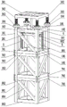
Fig. 1 is a schematic structural diagram of the present invention;
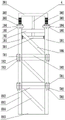
fig. 2 is a schematic front view of the present invention;
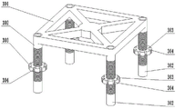
fig. 3 is a schematic structural view of a jacking adjusting bracket of the present invention;
fig. 4 is a schematic front view of a jacking-adjusting bracket of the present invention;
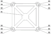
fig. 5 is a schematic top view of a jacking-adjusting bracket according to the present invention;
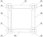
fig. 6 is a schematic structural view of the jacking-supporting frame of the present invention;
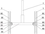
fig. 7 is a front view schematically illustrating a jacking-supporting frame of the present invention;
fig. 8 is a schematic top view of the jacking-supporting frame of the present invention;
fig. 9 is a schematic structural view of the jacking cross beam of the present invention;
fig. 10 is a schematic front view of the jacking cross beam of the present invention;
FIG. 11 is a schematic structural view of the joint of the standard support joint of the present invention;
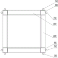
FIG. 12 is a schematic structural view of a support standard knot according to the present invention;
fig. 13 is a schematic top view of the middle support standard knot of the present invention.
In the figure, 101-upright post, 102-upper connecting beam, 103-lower connecting beam, 104-supporting plate, 105-triangular ribbed plate, 106-diagonal brace, 201-jacking cross beam, 202-flange plate, 203-sliding plate, 301-horizontal top frame, 302-cylindrical adjusting column, 303-locking nut, 304-operating groove, 4-hydraulic jack, 5-vertical sliding rail rod, 601-strip-shaped vertical hole, 602-locking bolt, 701-upper vertical sleeve, 702-lower vertical sleeve, 703-connecting bolt, 801-upright post I, 802-upper connecting beam I, 803-lower connecting beam I, 804-diagonal brace I.
Detailed Description
A jig frame device for a steel structure overweight girder with adjustable supporting height is shown in attached drawings 1-10, and comprises a plurality of supporting standard sections which are distributed up and down and are detachably connected, wherein a jacking support frame detachably connected with the supporting standard sections is arranged on the upper side of the supporting standard sections positioned on the top, and the jacking support frame comprises four upright columns 101 made of square steel, four upper connecting beams 102 which are horizontally fixed on the upper parts of the upright columns 101 and are distributed in a rectangular shape, and four lower connecting beams 103 which are horizontally fixed on the bottom ends of the upright columns 101 and are distributed in a rectangular shape; vertical sliding rails are arranged between the upper connecting beam 102 positioned on the left side and the lower connecting beam 103 positioned on the left side, and between the upper connecting beam 102 positioned on the right side and the lower connecting beam 103 positioned on the right side, a jacking cross beam 201 is arranged between the two vertical sliding rails, two ends of the jacking cross beam 201 are respectively in sliding connection with the two vertical sliding rails, and a locking mechanism is arranged between the end part of the jacking cross beam 201 and the vertical sliding rails; a jacking adjusting frame is arranged on the upper side of the jacking supporting frame, the jacking adjusting frame comprises a rectangular horizontal top frame 301 and four vertically-arranged cylindrical adjusting columns 302 fixed at four bottom corners of the horizontal top frame 301, and the four cylindrical adjusting columns 302 respectively movably penetrate through the four upright posts 101; the middle part of the side surface of the cylindrical adjusting column 302 is provided with external threads, and the middle part of the side surface is screwed with a locking nut 303 the lower surface of which is abutted against the top end surface of the upright column 101; an upward hydraulic jack 4 is arranged between the jacking cross beam 201 and the horizontal top frame 301, and the bottom of a machine base of the hydraulic jack 4 is fixedly connected to the jacking cross beam 201.
The utility model discloses the structural design of well support standard festival, jacking support frame, jacking alignment jig has realized the detachable connection of this bed-jig device, the convenience when having increased the transport. The structural design of the support standard knots realizes the rough adjustment of the height of the jig frame device, namely the number of the support standard knots is selected according to the target height. The structural design of jacking support frame, jacking alignment jig for the length that cylindrical adjusting post 302 overlaps in stand 101 can be freely, continuously adjusted, and then has realized the freedom of this bed-jig device height, continuously adjusted, at first utilizes hydraulic jack 4 to jack the jacking alignment jig to target height during the regulation, recycles lock nut 303 and locks the height of jacking alignment jig. Jacking crossbeam 201's structural design provides the bottom sprag effect for hydraulic jack 4, jacking crossbeam 201, the structural design of vertical slide rail makes hydraulic jack 4's position can adjust in a flexible way, and then the altitude mixture control scope of jacking alignment jig has been increased, be located the bottom of jacking support frame when jacking crossbeam 201 promptly, hydraulic jack 4 position is lower, realize the altitude mixture control of jacking alignment jig minizone, be located the top of jacking support frame when jacking crossbeam 201, hydraulic jack 4 position is when higher, realize the altitude mixture control on a large scale of jacking alignment jig.
During installation, firstly, each supporting standard section is placed below an overweight girder to be supported by a hoisting machine, the specific placement position needs to be positioned in advance and connected with the upper and lower adjacent supporting standard sections, then, the jacking adjusting frame is placed on the upper side of the supporting standard section at the top, so that the cylindrical adjusting columns 302 are sleeved with the upright columns 101 in a one-to-one correspondence manner, then, the height of the jacking cross beam 201 is adjusted by utilizing the vertical sliding rail in a sliding manner, the stroke of a piston rod of the hydraulic jack 4 can reach the target height of the jig frame device, and after the height of the jacking cross beam 201 is adjusted properly, the height of the jacking cross beam 201 is locked by utilizing the locking mechanism; then, the hydraulic jack 4 is started, under the hydraulic drive, a piston rod of the hydraulic jack 4 jacks the horizontal top frame 301 to ascend (before jacking, the piston rod of the hydraulic jack 4 can be in contact with the horizontal top frame 301 or can not be in contact with the horizontal top frame 301, but the horizontal top frame 301 needs to be kept in a horizontal state), and when the piston rod ascends, the length of the cylindrical adjusting column 302 sleeved on the upright column 101 is shortened until the horizontal top frame 301 reaches the target height, the four locking nuts 303 are screwed in sequence, and the positions of the four cylindrical adjusting columns 302 are locked; and finally, retracting the hydraulic jack 4 to reset, thereby completing the installation of the jig frame device. The utility model overcomes the problem that the bed-jig for the overweight girder is inconvenient to carry and can not freely adjust the supporting height.
In the use process, the weight of the overweight girder is supported by the supporting standard knot, the jacking support frame and the jacking adjusting frame, wherein the weight bearing of the joint of the jacking support frame and the jacking adjusting frame is realized by the four locking nuts 303, the support is stable and reliable, the hydraulic jack 4 does not need to bear the load of the overweight girder, the long-term support of the hydraulic jack 4 is avoided, the construction cost is saved, and meanwhile, the problem that the supporting function is lost due to the fault of the hydraulic jack 4 is avoided.
As shown in fig. 1, fig. 2, fig. 9, and fig. 10, the vertical slide rail includes two vertical slide rail rods 5 distributed in parallel in front and back, and two ends of the jacking cross beam 201 are fixedly connected with two sliding plates 203 that are transversely upright and clamped between the vertical slide rail rods 5 through a flange 202; the locking mechanism comprises a strip-shaped vertical hole 601 which is arranged on the vertical slide rail rod 5 positioned at the front side and is penetrated in the front and back direction, and two locking bolts 602 which are screwed on the front surface of the sliding plate 203 and penetrate through the strip-shaped vertical hole 601.
This structural design has realized the sliding connection of jacking crossbeam 201 and vertical slide rail to can be after sliding with the position locking of jacking crossbeam 201, and the locking simple operation.
As shown in fig. 1, fig. 2, fig. 6, fig. 7 and fig. 8, a disc-shaped support plate 104 is fixedly sleeved on the top end portion of the upright post 101, and four triangular ribs 105 which are uniformly distributed are fixed between the support plate 104 and the upright post 101.
The structural design of the support plate 104 effectively increases the contact area between the upright column 101 and the locking nut 303, so that the supporting effect of the upright column 101 on the locking nut 303 is improved, and the structural reliability of the jig frame device is effectively improved. The structural design of the triangular rib plates 105 effectively improves the structural firmness of the joint of the support plate 104 and the upright post 101, and further ensures the support effect of the upright post 101 on the locking nut 303.
As shown in the attached drawings 1, 2, 6, 7, 11, 12 and 13, the upper and lower adjacent support standard sections and the jacking support frame are detachably connected through four pairs of plug pin mechanisms which are distributed in a rectangular shape; the bolt mechanism comprises an upper vertical sleeve 701 fixed at the bottom end of the support standard joint or the bottom end of the jacking support frame, a lower vertical sleeve 702 fixed at the top end of the support standard joint, and a connecting bolt 703 penetrating through the upper vertical sleeve 701 and the lower vertical sleeve 702, wherein the upper surface of the lower vertical sleeve 702 is tightly attached to the lower surface of the upper vertical sleeve 701.
This structural design has realized between the adjacent support standard festival from top to bottom, has supported the dismantlement between standard festival and the jacking support frame and be connected, and the installation, dismantle the simple operation, improved the work efficiency when this bed-jig device assembles, demolishs.
As shown in fig. 1, fig. 2, fig. 11, fig. 12, and fig. 13, the support standard joint includes four upright posts I801 made of square steel, four upper connecting beams I802 horizontally fixed to the top end of the upright posts I801 and distributed in a rectangular shape, and four lower connecting beams I803 horizontally fixed to the bottom end of the upright posts I801 and distributed in a rectangular shape.
As shown in fig. 1, fig. 2, fig. 6, fig. 7, fig. 11, fig. 12, and fig. 13, diagonal braces 106 are disposed between the upper connecting beam 102 located on the front side and the lower connecting beam 103 located on the front side, and between the upper connecting beam 102 located on the rear side and the lower connecting beam 103 located on the rear side; inclined supporting rods I804 are arranged between the upper connecting beam I802 and the lower connecting beam I803 which are opposite up and down.
As shown in fig. 1 to 5, a plurality of operating grooves 304 are formed on an outer side wall of the lock nut 303, and the operating grooves are equidistantly distributed and vertically penetrate through the operating grooves.
This structural design has effectively increased the non-skid property of lock nut 303 lateral wall, rotates lock nut 303 when convenient locking operation.
In the specific implementation process, the horizontal top frame 301 comprises a rectangular square frame and a cross-shaped inclined rod fixed inside the rectangular square frame, a disc-shaped upper supporting plate is integrally arranged at the intersection part of the cross-shaped inclined rod, and the top end surface of the piston rod of the hydraulic jack 4 is in contact with the upper supporting plate. The upright post 101, the upper connecting beam 102, the lower connecting beam 103, the diagonal brace 106, the horizontal top frame 301, the upright post I801, the upper connecting beam I802, the lower connecting beam I803 and the diagonal brace I804 are all made of galvanized square steel tubes, wherein the upright post 101 and the upright post I801 are both made of 120 galvanized square steel tubes, and the diagonal brace 106 and the diagonal brace I804 are both made of 100 galvanized square steel tubes.
Claims (7)
1. The utility model provides a steel construction is bed-jig device for overweight girder with adjustable supporting height which characterized in that: the jacking support frame comprises four upright posts (101) made of square steel, four upper connecting beams (102) horizontally fixed at the upper parts of the upright posts (101) and distributed in a rectangular manner, and four lower connecting beams (103) horizontally fixed at the bottom ends of the upright posts (101) and distributed in a rectangular manner; vertical sliding rails are arranged between the upper connecting beam (102) on the left side and the lower connecting beam (103) on the left side, and between the upper connecting beam (102) on the right side and the lower connecting beam (103) on the right side, a jacking cross beam (201) is arranged between the two vertical sliding rails, two ends of the jacking cross beam (201) are respectively connected with the two vertical sliding rails in a sliding manner, and a locking mechanism is arranged between the end part of the jacking cross beam (201) and the vertical sliding rails; a jacking adjusting frame is arranged on the upper side of the jacking supporting frame and comprises a rectangular horizontal top frame (301) and four vertically-arranged cylindrical adjusting columns (302) which are fixed at four bottom corners of the horizontal top frame (301), and the four cylindrical adjusting columns (302) are respectively movably penetrated through the four upright posts (101); the middle part of the side surface of the cylindrical adjusting column (302) is provided with an external thread, and the middle part of the side surface is screwed with a locking nut (303) the lower surface of which is abutted against the top end surface of the upright column (101); a hydraulic jack (4) with an upward direction is arranged between the jacking cross beam (201) and the horizontal top frame (301), and the bottom of a machine base of the hydraulic jack (4) is fixedly connected with the jacking cross beam (201).
2. The jig frame device for the steel structure overweight girder with adjustable supporting height according to claim 1, characterized in that: the vertical slide rail comprises two vertical slide rail rods (5) which are distributed in parallel front and back, and two ends of the jacking cross beam (201) are fixedly connected with two sliding plates (203) which are transversely upright and clamped between the vertical slide rail rods (5) through flange plates (202); the locking mechanism comprises a vertical slide rail rod (5) arranged on the front side, a strip-shaped vertical hole (601) which is through from front to back and two locking bolts (602) which are screwed on the front surface of the sliding plate (203) and penetrate through the strip-shaped vertical hole (601).
3. The jig frame device for the steel structure overweight girder with adjustable supporting height according to claim 1, characterized in that: the top end part of the upright post (101) is fixedly sleeved with a disc-shaped supporting plate (104), and four triangular rib plates (105) which are uniformly distributed are fixed between the supporting plate (104) and the upright post (101).
4. The jig frame device for the steel structure overweight girder with adjustable supporting height according to claim 1, characterized in that: the upper and lower adjacent supporting standard sections and the jacking support frame are detachably connected through four pairs of plug pin mechanisms which are distributed in a rectangular shape; the bolt mechanism comprises an upper vertical sleeve (701) fixed at the bottom end of the support standard joint or the bottom end of the jacking support frame, a lower vertical sleeve (702) fixed at the top end of the support standard joint, and a connecting bolt (703) penetrating through the upper vertical sleeve (701) and the lower vertical sleeve (702), wherein the upper surface of the lower vertical sleeve (702) is tightly attached to the lower surface of the upper vertical sleeve (701).
5. The jig frame device for the steel structure overweight girder with adjustable supporting height according to claim 1, characterized in that: the supporting standard joint comprises four upright posts I (801) made of square steel, four upper connecting beams I (802) which are horizontally fixed at the top ends of the upright posts I (801) and distributed in a rectangular mode and four lower connecting beams I (803) which are horizontally fixed at the bottom ends of the upright posts I (801) and distributed in a rectangular mode.
6. The jig frame device for the steel structure overweight girder with adjustable supporting height of claim 5, characterized in that: inclined support rods (106) are arranged between the upper connecting beam (102) positioned on the front side and the lower connecting beam (103) positioned on the front side, and between the upper connecting beam (102) positioned on the rear side and the lower connecting beam (103) positioned on the rear side; inclined support rods I (804) are arranged between the upper connecting beam I (802) and the lower connecting beam I (803) which are opposite up and down.
7. The jig frame device for the steel structure overweight girder with adjustable supporting height according to claim 1, characterized in that: the outer side wall of the locking nut (303) is provided with a plurality of operating grooves (304) which are distributed at equal intervals and run through from top to bottom.
Priority Applications (1)
| Application Number | Priority Date | Filing Date | Title |
|---|---|---|---|
| CN202220952390.2U CN217129074U (en) | 2022-04-24 | 2022-04-24 | Steel construction overweight jig device for girder with adjustable supporting height |
Applications Claiming Priority (1)
| Application Number | Priority Date | Filing Date | Title |
|---|---|---|---|
| CN202220952390.2U CN217129074U (en) | 2022-04-24 | 2022-04-24 | Steel construction overweight jig device for girder with adjustable supporting height |
Publications (1)
| Publication Number | Publication Date |
|---|---|
| CN217129074U true CN217129074U (en) | 2022-08-05 |
Family
ID=82648272
Family Applications (1)
| Application Number | Title | Priority Date | Filing Date |
|---|---|---|---|
| CN202220952390.2U Active CN217129074U (en) | 2022-04-24 | 2022-04-24 | Steel construction overweight jig device for girder with adjustable supporting height |
Country Status (1)
| Country | Link |
|---|---|
| CN (1) | CN217129074U (en) |
Cited By (9)
| Publication number | Priority date | Publication date | Assignee | Title |
|---|---|---|---|---|
| CN115162773A (en) * | 2022-09-01 | 2022-10-11 | 中建八局第二建设有限公司 | Temporary supporting device for large-scale suspension steel structure and construction method |
| CN116065507A (en) * | 2022-10-31 | 2023-05-05 | 中建桥梁有限公司 | A prefabricated steel tower assembly tire frame system |
| CN116495673A (en) * | 2023-05-16 | 2023-07-28 | 中科睿格(烟台)技术服务有限责任公司 | Lifting device for satellite assembly |
| CN116493709A (en) * | 2023-06-21 | 2023-07-28 | 山西八建集团有限公司 | Preheating welding device for steel plate on conversion truss |
| CN116838071A (en) * | 2023-08-02 | 2023-10-03 | 远东幕墙(珠海)有限公司 | Temporary working platform suitable for laminated special-shaped steel structure and construction method thereof |
| CN116971623A (en) * | 2023-07-17 | 2023-10-31 | 贵州乾顺基建工程有限责任公司 | A jacking support device and construction method for building construction |
| CN118601340A (en) * | 2024-07-03 | 2024-09-06 | 徐坚梁 | Thousand-ton synchronous unloading node |
| CN118790898A (en) * | 2024-09-14 | 2024-10-18 | 中建三局城建有限公司 | Narrow and deep foundation pit material stacking platform and method |
| CN118880922A (en) * | 2024-10-09 | 2024-11-01 | 中铁九局集团第四工程有限公司 | An assembled variable height steel structure foundation |
-
2022
- 2022-04-24 CN CN202220952390.2U patent/CN217129074U/en active Active
Cited By (10)
| Publication number | Priority date | Publication date | Assignee | Title |
|---|---|---|---|---|
| CN115162773A (en) * | 2022-09-01 | 2022-10-11 | 中建八局第二建设有限公司 | Temporary supporting device for large-scale suspension steel structure and construction method |
| CN116065507A (en) * | 2022-10-31 | 2023-05-05 | 中建桥梁有限公司 | A prefabricated steel tower assembly tire frame system |
| CN116495673A (en) * | 2023-05-16 | 2023-07-28 | 中科睿格(烟台)技术服务有限责任公司 | Lifting device for satellite assembly |
| CN116493709A (en) * | 2023-06-21 | 2023-07-28 | 山西八建集团有限公司 | Preheating welding device for steel plate on conversion truss |
| CN116493709B (en) * | 2023-06-21 | 2023-09-05 | 山西八建集团有限公司 | Preheating welding device for steel plate on conversion truss |
| CN116971623A (en) * | 2023-07-17 | 2023-10-31 | 贵州乾顺基建工程有限责任公司 | A jacking support device and construction method for building construction |
| CN116838071A (en) * | 2023-08-02 | 2023-10-03 | 远东幕墙(珠海)有限公司 | Temporary working platform suitable for laminated special-shaped steel structure and construction method thereof |
| CN118601340A (en) * | 2024-07-03 | 2024-09-06 | 徐坚梁 | Thousand-ton synchronous unloading node |
| CN118790898A (en) * | 2024-09-14 | 2024-10-18 | 中建三局城建有限公司 | Narrow and deep foundation pit material stacking platform and method |
| CN118880922A (en) * | 2024-10-09 | 2024-11-01 | 中铁九局集团第四工程有限公司 | An assembled variable height steel structure foundation |
Similar Documents
| Publication | Publication Date | Title |
|---|---|---|
| CN110722318A (en) | Precise adjustable steel truss assembling jig frame and assembling method | |
| CN214573987U (en) | Conveniently adjusted lattice column positioning frame | |
| CN213952963U (en) | Silo conical shell formwork support platform | |
| CN113802880A (en) | Combined supporting structure for mounting large-span steel beam | |
| CN213626572U (en) | Tool type external cantilever operation platform | |
| CN110925531B (en) | Independent steel support tripod and using method thereof | |
| CN210684499U (en) | Hydraulic jacking device for pier column | |
| CN114086594B (en) | Support welding tool for offshore wind power jacket | |
| CN214575722U (en) | A construction engineering support | |
| CN217500228U (en) | But height-adjusting's lattice column | |
| CN209799403U (en) | An anti-instability column foot anchor bolt bracket | |
| CN217776061U (en) | Welding device for reinforcing hoop of steel reinforcement cage | |
| CN112723094A (en) | Integrated wall-attached device based on synchronous climbing of light steel platform | |
| CN115652801B (en) | Pile foundation structure for support for bridge construction | |
| CN212740622U (en) | Hydraulic lifting device for on-site installation of large steel storage tank | |
| CN214144681U (en) | Striding type template support system | |
| CN212954042U (en) | Lattice formula cable saddle hoist and mount portal | |
| CN219060873U (en) | A High Formwork System for Large Industrial Plants | |
| CN113073858A (en) | Steel column installation device and installation method | |
| CN221778954U (en) | A high pile foundation photovoltaic module installation work platform | |
| CN221232443U (en) | Assembling tool for prestress anchor bolt cage of fan unit | |
| CN119735130B (en) | A double-support structure for repairing and replacing damaged photovoltaic load-bearing cable supports and its application method | |
| CN219387254U (en) | Pushing bracket for steel box girder | |
| CN220267151U (en) | Lifting type supporting device | |
| CN223931043U (en) | Absorber tower bottom plate support structure assembly |
Legal Events
| Date | Code | Title | Description |
|---|---|---|---|
| GR01 | Patent grant | ||
| GR01 | Patent grant |