CN217099034U - Novel ring mould pellet feed briquetting machine - Google Patents
Novel ring mould pellet feed briquetting machine Download PDFInfo
- Publication number
- CN217099034U CN217099034U CN202220718099.9U CN202220718099U CN217099034U CN 217099034 U CN217099034 U CN 217099034U CN 202220718099 U CN202220718099 U CN 202220718099U CN 217099034 U CN217099034 U CN 217099034U
- Authority
- CN
- China
- Prior art keywords
- feeding
- box
- ring die
- filter plate
- motor
- Prior art date
- Legal status (The legal status is an assumption and is not a legal conclusion. Google has not performed a legal analysis and makes no representation as to the accuracy of the status listed.)
- Active
Links
Images


Landscapes
- Processing And Handling Of Plastics And Other Materials For Molding In General (AREA)
Abstract
The utility model provides a novel ring die pellet feed briquetting machine, the power distribution box comprises a box body, the ring die, a plurality of compression rollers, feeding subassembly and filtration piece, the ring die rotates to be supported in the box, a plurality of compression rollers are arranged in the box, the compression roller is connected in the box inner wall, the compression roller is clearance fit with the ring die inner wall, be equipped with the driving piece between ring die and box, the rotation of the relative box of driving piece control ring die, be equipped with a plurality of cutters in the box, cutter and ring die outer wall are clearance fit, feed inlet and discharge gate have been seted up on the box, feed inlet department is equipped with the feeding subassembly, the feeding subassembly communicates inside the ring die, discharge gate department is equipped with the control, the switch of control discharge gate, the box is located on the support, the box has the filtration piece, filter piece corresponds with the discharge gate position in vertical direction. The utility model discloses can convenient to use, the screening of being convenient for, the suppression of being convenient for is even.
Description
Technical Field
The utility model relates to a fodder pelletization equipment technical field, concretely relates to novel ring mould pellet feed briquetting machine.
Background
A ring mould particle feed machine belongs to feed granulating equipment, and is a feed processing machine for directly pressing crushed materials of corn, bean pulp, straw, grass, rice husk and the like into particles.
The ring die granulator is the main feed machinery for producing granulated feed, the performance of the ring die granulator determines the feed processing yield to a great extent, and the ring die granulator plays a very important role in the feed processing process.
In view of the above-mentioned related technologies, the inventor believes that, after the conventional ring die pellet feed press completes the pressing, the pressed raw materials are generally directly transported out, so that most of the transported raw materials are the mixture of granular raw materials and powdery raw materials, and some granular raw materials with smaller particle size exist after the pressing, which need to be subsequently screened, so that the press is inconvenient to use.
SUMMERY OF THE UTILITY MODEL
In order to facilitate the use, be convenient for sieve, it is even to be convenient for suppress, and the application provides a novel ring mould pellet feed briquetting machine.
The application provides a novel ring mould pellet feed briquetting machine adopts following technical scheme:
a novel ring die granulated feed pressing machine, which comprises a box body, a ring die, a plurality of compression rollers, a feeding assembly and a filtering piece, the ring die is rotatably supported in the box body, a plurality of compression rollers are arranged in the box body, the compression rollers are connected with the inner wall of the box body, the compression roller is in clearance fit with the inner wall of the ring die, a driving piece is arranged between the ring die and the box body, the driving piece controls the ring die to rotate relative to the box body, a plurality of cutters are arranged in the box body, the cutter is in clearance fit with the outer wall of the ring die, a feed inlet and a discharge outlet are arranged on the box body, a feeding component is arranged at the feeding port and communicated with the interior of the circular mold, a control part is arranged at the discharging port, the control piece controls the opening and closing of the discharge hole, the box body is arranged on the support, the filtering piece is arranged below the box body, and the filtering piece corresponds to the discharge hole in the vertical direction.
Further, it includes bottom plate, filter plate, first collecting box and second collecting box to filter, the filter plate is arranged in on the bottom plate, the filter plate in vertical direction with the discharge gate position corresponds, first collecting box is located the filter plate below, the second collecting box is located filter plate one side, the filter plate slope sets up, the filter plate is close to one side of second collecting box is less than in vertical direction the filter plate is kept away from one side of second collecting box.
Furthermore, a vibration motor is arranged on the bottom plate, the output end of the vibration motor is vertically upward, and the filter plate is connected to the output end of the vibration motor.
Furthermore, a feeding hopper is arranged at the feeding port.
Further, be equipped with the agitator tank in the box, feed hopper bottom communicate in the agitator tank top, be equipped with (mixing) shaft and agitator motor on the agitator tank, the (mixing) shaft is vertical to be arranged in the agitator tank, agitator motor locates on the agitator tank, the agitator motor output passes the agitator tank and be connected to the (mixing) shaft, agitator motor control the rotation of (mixing) shaft, be connected with a plurality of stirring vane on the (mixing) shaft.
Furthermore, the feeding assembly comprises a feeding pipe, a feeding motor and a feeding shaft, a through hole is formed in the bottom of the stirring box, a connecting pipe is connected to the through hole, one end of the connecting pipe, which is far away from the stirring box, is communicated with the feeding pipe, one end of the feeding pipe is communicated with the interior of the ring die, a bearing is arranged between the outer wall of the feeding pipe and the ring die, the feeding shaft is arranged in the feeding pipe, the feeding motor is connected to the outer wall of the feeding pipe, the feeding motor is connected to the feeding shaft, the feeding motor controls the rotation of the feeding shaft, the side wall of the feeding shaft is connected with auger blades, and the auger blades and the inner wall of the feeding pipe are in clearance fit.
Furthermore, a plurality of self-locking universal wheels are connected below the bottom plate.
Furthermore, the two opposite side walls of the first collecting box are respectively connected with a handle, and the two opposite side walls of the second collecting box are respectively connected with a handle.
In summary, the present application includes at least one of the following beneficial technical effects:
1. raw materials are added into the ring die through the feeding hole and the feeding assembly, the ring die is driven to rotate through the driving piece, the compression roller and the ring die move relatively in the rotating process of the ring die, the powdery raw materials are pressed into small holes of the ring die by the compression roller, the pressed granular raw materials move out of the outer wall of the ring die and are cut off by the cutter, the granular raw materials drop downwards and move out through the discharging hole, and the pressed raw materials are screened by the filter piece to distinguish the powdery raw materials from the granular raw materials, so that the ring die is convenient to use;
2. a plurality of self-locking universal wheels are connected below the bottom plate, two opposite side walls of the first collecting box are respectively connected with handles, and two opposite side walls of the second collecting box are respectively connected with handles, so that the device is convenient to use and move, and the flexibility of the device is improved;
3. the auger blade is in clearance fit with the inner wall of the feeding pipe, so that raw materials can be conveniently added into the ring die, the adding speed can be conveniently controlled, the feeding is stable, the structure is simple, and the use is convenient.
Drawings
FIG. 1 is a schematic structural view of a novel circular mold pellet feed press of the present invention;
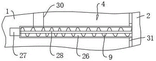
FIG. 2 is an enlarged view of a portion A of FIG. 1 according to the present invention;
FIG. 3 is a schematic view of the overall structure of the filter member of the present invention;
FIG. 4 is a schematic view of the overall structure of the stirring box of the present invention;
fig. 5 is a schematic view of the overall structure of the feeding assembly of the present invention.
Description of reference numerals: 1. a box body; 2. performing ring die; 3. a compression roller; 4. a feed assembly; 5. a filter member; 6. a cutter; 7. a feed inlet; 8. a discharge port; 9. a screw blade; 10. a control member; 11. a support; 12. a valve; 13. a discharge pipe; 14. a base plate; 15. filtering the plate; 16. a first collection tank; 17. a second collection tank; 18. vibrating a motor; 19. a self-locking universal wheel; 20. a handle; 21. a feed hopper; 22. a stirring box; 23. a stirring shaft; 24. a stirring motor; 25. a stirring blade; 26. feeding pipes; 27. a feeding motor; 28. a feeding shaft; 29. a through hole; 30. a connecting pipe; 31. and a bearing.
Detailed Description
In order to make the objects, technical solutions and advantages of the embodiments of the present invention clearer, the technical solutions of the embodiments of the present invention will be clearly and completely described below with reference to fig. 1 to 5 of the embodiments of the present invention. It is to be understood that the embodiments described are only some of the embodiments of the present invention, and not all of them. All other embodiments, which can be derived from the description of the embodiments of the present invention by a person skilled in the art, are within the scope of the present invention.
As shown in fig. 1, a novel ring die pellet feed press comprises a box body 1 and a ring die 2, a plurality of compression rollers 3, feeding subassembly 4 and filtration piece 5, 2 rotation supports in box 1 of ring mould, box 1 is arranged in to a plurality of compression rollers 3, compression roller 3 connects in 1 inner wall of box, compression roller 3 is clearance fit with 2 inner walls of ring mould, be equipped with the driving piece between ring mould 2 and box 1, the relative box 1's of driving piece control ring mould 2 rotation, be equipped with a plurality of cutters 6 in the box 1, cutter 6 is clearance fit with 2 outer walls of ring mould, feed inlet 7 and discharge gate 8 have been seted up on the box 1, feed inlet 7 department is equipped with feeding subassembly 4, feeding subassembly 4 communicates inside ring mould 2, 8 departments of discharge gate are equipped with control 10, the switch of control 10 control discharge gate 8, box 1 is located on support 11, box 1 has filtration piece 5, filtration piece 5 corresponds with 8 positions of discharge gate in vertical direction.
As shown in figure 1, the raw materials are added into a ring die 2 through a feeding hole 7 and a feeding assembly 4, the ring die 2 is driven to rotate through a driving piece, the ring die 2 rotates, a compression roller 3 and the ring die 2 move relatively, the compression roller 3 presses the powdery raw materials into small holes of the ring die 2, the granular raw materials after being pressed move out of the outer wall of the ring die 2 and are cut off by a cutter 6, the granular raw materials drop downwards and move out through a discharging hole 8, the raw materials after being pressed are screened by a filter piece 5, the powdery raw materials and the granular raw materials are distinguished, and the ring die is convenient to use.
As shown in fig. 1, the driving member includes a driving motor (the driving motor is not shown in the figure), the structure is simple, the use is convenient, the rotation of the ring die 2 is convenient to control, the control member 10 includes a valve 12, a discharging pipe 13 is arranged at the discharging port 8, the valve 12 is connected to the discharging pipe 13, the on-off of the discharging port 8 is convenient to control, and the use is convenient.
As shown in fig. 1 and 2, the filter element 5 includes a bottom plate 14, a filter plate 15, a first collection box 16 and a second collection box 17, the filter plate 15 is disposed on the bottom plate 14, the filter plate 15 corresponds to the discharge port 8 in the vertical direction, the first collection box 16 is disposed below the filter plate 15, the second collection box 17 is disposed on one side of the filter plate 15, the filter plate 15 is disposed in an inclined manner, one side of the filter plate 15 close to the second collection box 17 is lower than one side of the filter plate 15 away from the second collection box 17 in the vertical direction, a vibration motor 18 is disposed on the bottom plate 14, the output end of the vibration motor 18 is vertically upward, the filter plate 15 is connected to the output end of the vibration motor 18, a vibration motor 18 is disposed to accelerate the screening, the use is facilitated, the raw material falls out from the discharge port 8, the screening is performed on the filter plate 15, the powdery raw material and the granular raw material with smaller size fall down into the first collection box 16, and other granular raw materials move along the filter plate 15 towards the direction close to the second collection box 17, other granular raw materials drop to the second collecting box 17, are convenient for sieve and collect, convenient to use, simple structure.
As shown in fig. 1 and 2, a plurality of self-locking universal wheels 19 are connected under the bottom plate 14, handles 20 are respectively connected to two opposite side walls of the first collecting box 16, and handles 20 are respectively connected to two opposite side walls of the second collecting box 17, so that the device is convenient to use, the position of the device is convenient to move, and the flexibility of the device is improved.
As shown in fig. 1 and 4, a feeding funnel 21 is disposed at the feeding port 7, so that raw materials can be added into the box body 1 conveniently, and the use is convenient.
As shown in fig. 4, be equipped with agitator tank 22 in the box 1, feed hopper 21 bottom communicates in agitator tank 22 top, be equipped with (mixing) shaft 23 and agitator motor 24 on the agitator tank 22, agitator shaft 23 is vertical to be arranged in agitator tank 22, agitator motor 24 is located on agitator tank 22, agitator motor 24 output passes agitator tank 22 and is connected in (mixing) shaft 23, agitator motor 24 control (mixing) shaft 23's rotation, be connected with a plurality of stirring vane 25 on the (mixing) shaft 23, stir the raw materials before the raw materials are suppressed, when needing several kinds of raw materials to mix the suppression, make multiple raw materials misce bene, be favorable to promoting the suppression quality, it is even to be convenient for suppress.
As shown in fig. 2 and 5, the feeding assembly 4 includes a feeding pipe 26, a feeding motor 27 and a feeding shaft 28, a through hole 29 is formed at the bottom of the stirring box 22, a connecting pipe 30 is connected to the through hole 29, one end of the connecting pipe 30 far away from the stirring box 22 is communicated with the feeding pipe 26, one end of the feeding pipe 26 is communicated with the inside of the ring mold 2, a bearing 31 is arranged between the outer wall of the feeding pipe 26 and the ring mold 2, the feeding shaft 28 is arranged in the feeding pipe 26, the feeding motor 27 is connected to the outer wall of the feeding pipe 26, the feeding motor 27 is connected to the feeding shaft 28, the feeding motor 27 controls the rotation of the feeding shaft 28, the side wall of the feeding shaft 28 is connected with an auger blade 9, the auger blade 9 and the inner wall of the feeding pipe 26 are in clearance fit, so as to facilitate adding raw materials into the ring mold 2, so as to facilitate controlling the adding speed, the feeding is stable, the structure is simple, and the use is convenient.
The implementation principle is as follows:
add the raw materials to feed hopper 21 in, start agitator motor 24, stir the raw materials, the raw materials after the stirring drops to material loading pipe 26 in through connecting pipe 30, according to the material loading condition, control material loading motor 27, when starting material loading motor 27, auger blade 9 promotes the raw materials and moves forward, adds the raw materials to ring mould 2 in, starts driving motor, and granular raw materials after the suppression drop downwards.
The valve 12 is opened, the raw materials drop downwards onto the filter plate 15, the vibration motor 18 is started, some raw materials drop downwards into the first collection box 16 through the filter plate 15, some raw materials move along the filter plate 15 and drop into the second collection box 17, the raw materials in the first collection box 16 are reprocessed according to actual requirements, and the raw materials in the second collection box 17 are transported and processed.
In the present invention, unless otherwise explicitly specified or limited, for example, it may be fixedly connected, detachably connected, or integrated; can be mechanically or electrically connected; they may be directly connected or indirectly connected through an intermediate medium, and may be connected through the inside of two elements or in an interaction relationship between two elements, unless otherwise specifically defined, and the specific meaning of the above terms in the present invention will be understood by those skilled in the art according to specific situations.
The foregoing is a preferred embodiment of the present invention, and it should be noted that, for those skilled in the art, a plurality of improvements and decorations can be made without departing from the principle of the present invention, and these improvements and decorations should also be regarded as the protection scope of the present invention.
Claims (8)
1. A novel ring mould pellet feed briquetting machine which characterized in that: comprises a box body (1), a ring die (2), a plurality of compression rollers (3), a feeding component (4) and a filtering piece (5), wherein the ring die (2) is rotatably supported in the box body (1), the compression rollers (3) are arranged in the box body (1), the compression rollers (3) are connected with the inner wall of the box body (1), the compression rollers (3) are in clearance fit with the inner wall of the ring die (2), a driving piece is arranged between the ring die (2) and the box body (1), the driving piece controls the ring die (2) to rotate relative to the box body (1), a plurality of cutters (6) are arranged in the box body (1), and the cutters (6) and the outer wall of the ring die (2) are in clearance fit,
feed inlet (7) and discharge gate (8) have been seted up on box (1), feed inlet (7) department is equipped with feeding subassembly (4), feeding subassembly (4) communicate in inside ring mould (2), discharge gate (8) department is equipped with control (10), control (10) control the switch of discharge gate (8), box (1) is located on support (11), box (1) has filtering piece (5), filter piece (5) in vertical direction with discharge gate (8) position corresponds.
2. A novel ring die pellet press as claimed in claim 1, wherein: it includes bottom plate (14), filter plate (15), first collecting box (16) and second collecting box (17) to filter piece (5), filter plate (15) are arranged in on bottom plate (14), filter plate (15) in vertical direction with discharge gate (8) position corresponds, first collecting box (16) are located filter plate (15) below, second collecting box (17) are located filter plate (15) one side, filter plate (15) slope sets up, filter plate (15) are close to one side of second collecting box (17) is less than in vertical direction filter plate (15) are kept away from one side of second collecting box (17).
3. A novel ring die pellet press as claimed in claim 2, wherein: the filter plate is characterized in that a vibration motor (18) is arranged on the bottom plate (14), the output end of the vibration motor (18) is vertically upward, and the filter plate (15) is connected to the output end of the vibration motor (18).
4. A novel ring die pellet press as claimed in claim 3, wherein: and a feeding funnel (21) is arranged at the feeding hole (7).
5. A novel ring die pellet press as claimed in claim 4, wherein: be equipped with agitator tank (22) in box (1), feed hopper (21) bottom communicate in agitator tank (22) top, be equipped with (mixing) shaft (23) and agitator motor (24) on agitator tank (22), agitator motor (23) are vertical to be arranged in agitator tank (22), agitator motor (24) are located on agitator tank (22), agitator motor (24) output passes agitator tank (22) and be connected in agitator shaft (23), agitator motor (24) control the rotation of (mixing) shaft (23), be connected with a plurality of stirring vane (25) on (mixing) shaft (23).
6. A novel ring die pellet press as claimed in claim 5, wherein: the feeding assembly (4) comprises a feeding pipe (26), a feeding motor (27) and a feeding shaft (28), a through hole (29) is formed in the bottom of the stirring box (22), a connecting pipe (30) is connected to the through hole (29), one end, far away from the stirring box (22), of the connecting pipe (30) is communicated with the feeding pipe (26), one end of the feeding pipe (26) is communicated with the inside of the ring die (2), a bearing (31) is arranged between the outer wall of the feeding pipe (26) and the ring die (2), the feeding shaft (28) is arranged in the feeding pipe (26), the feeding motor (27) is connected to the outer wall of the feeding pipe (26), the feeding motor (27) is connected to the feeding shaft (28), the feeding motor (27) controls the feeding shaft (28) to rotate, and the side wall of the feeding shaft (28) is connected with a packing auger blade (9), the auger blade (9) is in clearance fit with the inner wall of the feeding pipe (26).
7. A novel ring die pellet press as claimed in claim 6, wherein: a plurality of self-locking universal wheels (19) are connected below the bottom plate (14).
8. A novel ring die pellet press as claimed in claim 7, wherein: handles (20) are respectively connected to two opposite side walls of the first collecting box (16), and handles (20) are respectively connected to two opposite side walls of the second collecting box (17).
Priority Applications (1)
| Application Number | Priority Date | Filing Date | Title |
|---|---|---|---|
| CN202220718099.9U CN217099034U (en) | 2022-03-30 | 2022-03-30 | Novel ring mould pellet feed briquetting machine |
Applications Claiming Priority (1)
| Application Number | Priority Date | Filing Date | Title |
|---|---|---|---|
| CN202220718099.9U CN217099034U (en) | 2022-03-30 | 2022-03-30 | Novel ring mould pellet feed briquetting machine |
Publications (1)
| Publication Number | Publication Date |
|---|---|
| CN217099034U true CN217099034U (en) | 2022-08-02 |
Family
ID=82578853
Family Applications (1)
| Application Number | Title | Priority Date | Filing Date |
|---|---|---|---|
| CN202220718099.9U Active CN217099034U (en) | 2022-03-30 | 2022-03-30 | Novel ring mould pellet feed briquetting machine |
Country Status (1)
| Country | Link |
|---|---|
| CN (1) | CN217099034U (en) |
-
2022
- 2022-03-30 CN CN202220718099.9U patent/CN217099034U/en active Active
Similar Documents
| Publication | Publication Date | Title |
|---|---|---|
| CN109673277A (en) | Straw collecting, which crushes, is granulated all-in-one machine | |
| CN109480320A (en) | A kind of pellet crushing molding one | |
| CN111545130B (en) | 420 Type granulator that suitability is high | |
| CN218609250U (en) | Rotary extrusion type granulator | |
| CN115253900A (en) | Piglet feed granulating device and granulating process thereof | |
| CN220780204U (en) | Wet granulator | |
| CN218831900U (en) | Fodder screening pelletization all-in-one | |
| CN219522701U (en) | Raw material mixing device for woven bag production | |
| CN112778028A (en) | Method for preparing organic fertilizer by using straws | |
| CN212493283U (en) | Fodder reducing mechanism | |
| CN215429437U (en) | Organic fertilizer raw material reducing mechanism | |
| CN212661039U (en) | Can improve fodder granulator of feed utilization rate | |
| CN109530405A (en) | A kind of agricultural trade refuse treatment plant | |
| CN218516647U (en) | Improve fodder production efficiency's pelletization equipment | |
| CN109908830A (en) | A kind of biological organic fertilizer grinding device | |
| CN221753210U (en) | A granulation device for metformin glipizide tablets | |
| CN219616011U (en) | Forage grass foodstuff granulator | |
| CN221183619U (en) | Fertilizer screening plant | |
| CN207463357U (en) | Multifunctional particle machine | |
| CN221653588U (en) | Anti-sprinkling granulator for feed production | |
| CN220759995U (en) | Screening equipment for slow release fertilizer production | |
| CN218132319U (en) | Special crusher for chemical fertilizer | |
| CN220776611U (en) | Corn thresher mildenes and rot grain separating mechanism | |
| CN215197205U (en) | Gear type efficient crushing device for unformed feed | |
| CN219596551U (en) | Multistage stirring's raw materials processing is with high-speed mixing wet granulator |
Legal Events
| Date | Code | Title | Description |
|---|---|---|---|
| GR01 | Patent grant | ||
| GR01 | Patent grant |