Boiler harmful gas optimizes dust removal discharging equipment
Technical Field
The utility model relates to a relevant technical field is handled to the flue gas, specifically is a boiler harmful gas optimizes dust removal discharging equipment.
Background
The industrial boiler products are divided into two types, one is steam used for power generation or gas supply, for example, a chemical fertilizer plant can use steam for vaporization, coal is used as a raw material to synthesize chemical fertilizer, which is a typical industrial boiler, the industrial boiler also uses coal as the majority, a fuel gas is generally used for recovering waste heat by a waste heat boiler, but because the flue gas generated in the combustion process of the boiler is harmful gas, the flue gas needs to be treated in order to reach the emission standard, the existing flue gas treatment device usually filters dust particles in the flue gas through a filter screen, the surface of the filter screen is blocked by the dust particles in the flue gas after the filter screen is used for a long time, and the filter screen is usually inconvenient to be arranged inside, so that the filter screen is cleaned, the cleaning is troublesome, the existing flue gas treatment device is inconvenient to secondarily utilize the flue gas, and the flue gas utilization rate is low, the practicability is poor.
SUMMERY OF THE UTILITY MODEL
An object of the utility model is to provide a boiler harmful gas optimizes dust removal discharging equipment to solve the inconvenient filter screen that clears up of current flue gas processing apparatus who proposes in the above-mentioned background art, and inconvenient carry out the problem of reutilization to the flue gas.
In order to achieve the above object, the utility model provides a following technical scheme: an optimized dust-removing and discharging device for harmful gas in a boiler comprises a flue gas treatment box, a delivery pump and a filter screen,
the two ends of the interior of the flue gas treatment box are respectively provided with a desulfurization cavity and a dust removal cavity, and the two ends of the outer side of the flue gas treatment box are respectively provided with an exhaust pipe and an air inlet pipe;
the conveying pump is arranged on the outer side of the flue gas treatment box, two ends of the conveying pump are respectively connected with the solvent box and the spray pipe through conveying pipes, the solvent box is arranged at the top of the flue gas treatment box, the spray pipe is arranged on the inner wall of the desulfurization cavity, and a spray head is arranged below the spray pipe;
the filter screen sets up in the dust removal chamber, and the top in dust removal chamber has seted up the spout, and sliding connection has the montant in the spout simultaneously, the bottom of montant is provided with the clearance board, and the surface of montant is provided with the rack.
Preferably, an air guide channel is arranged inside the flue gas treatment box, two ends of the air guide channel are communicated with the desulfurization cavity and the dust removal cavity respectively, and a pressurizing fan is arranged inside the air guide channel.
By adopting the technical scheme, the flow speed of the flue gas can be improved, so that the treatment efficiency is improved.
Preferably, the top of the flue gas treatment box is provided with a motor, the output end of the motor is connected with a driving gear, and the driving gear is meshed with the rack.
By adopting the technical scheme, the filter screen can be conveniently cleaned.
Preferably, the filter screen is provided with two sets, and the bottom of filter screen is provided with the collecting box.
Through adopting above-mentioned technical scheme, can collect the dust on filter screen surface.
Preferably, the inside of blast pipe is provided with the impeller, and the impeller is connected with the generator, and the generator setting is in the bottom of blast pipe simultaneously.
Through adopting above-mentioned technical scheme, can carry out reutilization to the flue gas, improve the utilization ratio to the flue gas.
Compared with the prior art, the beneficial effects of the utility model are that: the boiler harmful gas optimizing dust-removing and discharging device,
(1) the vertical rod cleaning device is provided with the driving gear and the vertical rod, the driving gear is driven to rotate by the motor, the driving gear drives the vertical rod to slide downwards through the rack on the surface of the vertical rod, so that the vertical rod drives the cleaning plate at the bottom of the vertical rod to descend and be attached to the surface of the filter screen for cleaning, and meanwhile, the collecting box at the bottom of the filter screen can collect dust particles falling during cleaning, so that the vertical rod cleaning device is simple in structure, convenient for cleaning the filter screen and improved in convenience in use;
(2) be provided with impeller and generator, through set up the impeller in the blast pipe for the flue gas can promote the impeller and rotate when the exhaust, thereby makes the generator can generate electricity, so that carry out the reutilization to the flue gas, and the flow of flue gas can be improved to the pressurized fan in the air guide channel in the flue gas treatment box simultaneously, makes and can improve the flue gas and to the produced impact force of impeller, thereby improves the generating efficiency.
Drawings
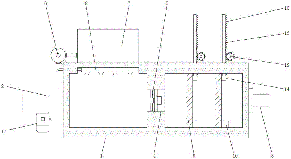
FIG. 1 is a schematic front view of the present invention;
FIG. 2 is a schematic view of the top view of the flue gas treatment box of the present invention;
fig. 3 is a schematic view of the sectional structure of the exhaust pipe of the present invention.
In the figure: 1. flue gas treatment box, 2, blast pipe, 3, intake pipe, 4, air guide channel, 5, booster fan, 6, delivery pump, 7, solvent case, 8, shower, 9, filter screen, 10, collecting box, 11, motor, 12, drive gear, 13, montant, 14, clearance board, 15, rack, 16, impeller, 17, generator.
Detailed Description
The technical solutions in the embodiments of the present invention will be described clearly and completely with reference to the accompanying drawings in the embodiments of the present invention, and it is obvious that the described embodiments are only some embodiments of the present invention, not all embodiments. Based on the embodiments in the present invention, all other embodiments obtained by a person skilled in the art without creative work belong to the protection scope of the present invention.
Referring to fig. 1-3, the present invention provides a technical solution: the utility model provides a boiler harmful gas optimizes dust removal discharging equipment, as shown in figure 1, desulfurization chamber and dust removal chamber have been seted up respectively to the inside both ends of flue gas treatment case 1, and the outside both ends of flue gas treatment case 1 are provided with blast pipe 2 and intake pipe 3 respectively, the inside of flue gas treatment case 1 is provided with air guide channel 4, and air guide channel 4's both ends link up with desulfurization chamber and dust removal chamber respectively mutually, air guide channel 4's inside is provided with forcing fan 5 simultaneously, when leading-in flue gas, can open forcing fan 5 rotation in the air guide channel 4, make the inside negative pressure that produces of flue gas treatment case 1, so that improve the leading-in efficiency to the flue gas, make the processing to the flue gas faster, improve the treatment effeciency.
As shown in fig. 1, the delivery pump 6 is arranged outside the flue gas treatment box 1, and the two ends of the delivery pump 6 are respectively connected with the solvent box 7 and the spray pipe 8 through the delivery pipes, meanwhile, the solvent box 7 is arranged at the top of the flue gas treatment box 1, the spray pipe 8 is arranged on the inner wall of the desulfurization cavity, and the spray head is arranged below the spray pipe 8, after the flue gas is guided into the dedusting cavity from the air inlet pipe 3, the dust particles in the flue gas can be filtered by the filter screen 9 in the dedusting cavity, then the flue gas can be guided into the desulfurization cavity through the air guide channel 4, and the solvent in the solvent box 7 is conveyed into the spray pipe 8 at the top of the desulfurization cavity through the delivery pump 6, so that the spray pipe 8 sprays the solvent to perform desulfurization and denitration on the flue gas, meanwhile, the pressurizing fan 5 in the air guide channel 4 can improve the conveying flow of the flue gas, and improve the treatment efficiency of the flue gas.
As shown in fig. 1 and 2, the filter screen 9 is disposed in the dust removing cavity, a sliding groove is formed in the top of the dust removing cavity, a vertical rod 13 is slidably connected in the sliding groove, a cleaning plate 14 is disposed at the bottom of the vertical rod 13, a rack 15 is disposed on the surface of the vertical rod 13, a motor 11 is disposed at the top of the smoke processing box 1, an output end of the motor 11 is connected with a driving gear 12, the driving gear 12 is meshed with the rack 15, when the filter screen 9 needs to be cleaned after long-time use, the motor 11 at the top of the smoke processing box 1 is opened to drive the driving gear 12 to rotate, when the driving gear 12 is used, the vertical rod 13 is driven by the rack 15 meshed with the surface of the vertical rod 13 to slide downwards in the sliding groove at the top of the dust removing cavity, so that the vertical rod 13 drives the cleaning plate 14 to descend and adhere to the surface of the filter screen 9 for cleaning, thereby cleaning the filter screen 9, the cleaning is convenient, and the cleaning efficiency is improved.
As shown in fig. 1, the filter screen 9 is provided with two sets, and the bottom of filter screen 9 is provided with collecting box 10, descends at cleaning plate 14 and clears up filter screen 9 simultaneously, and collecting box 10 of filter screen 9 bottom can collect the dust that drops in the clearance process, avoids the dust to scatter, improves its practicality.
As shown in fig. 1 and 3, the inside of exhaust pipe 2 is provided with impeller 16, and impeller 16 is connected with generator 17, generator 17 sets up the bottom at exhaust pipe 2 simultaneously, handle the back to the flue gas, the flue gas can be followed exhaust pipe 2 and discharged, the flue gas can promote the rotation of impeller 16 in the exhaust pipe 2 simultaneously, thereby make the generator 17 of exhaust pipe 2 bottom can generate electricity, so that carry out reutilization to the flue gas, still can set up the inner wall of exhaust pipe 2 into the toper, make and compress the flue gas, thereby improve the impact force to impeller 16, make there is better generating efficiency.
The working principle is as follows: when the device for optimizing dust removal and emission of harmful gas in a boiler is used, the filter screen 9 and the spray pipe 8 in the flue gas treatment box 1 are used for spraying a solvent, so that dust removal and desulfurization and denitrification can be performed on flue gas, when the filter screen 9 needs to be cleaned, only the motor 11 at the top of the flue gas treatment box 1 needs to be opened to drive the driving gear 12 to rotate, and through the rack 15 on the surface of the vertical rod 13, so that the vertical rod 13 and the cleaning plate 14 can be driven to descend in the rotating process of the driving gear 12, the cleaning plate 14 can be used for cleaning the surface of the filter screen 9, the whole operation is completed, and the content which is not described in detail in the specification belongs to the prior art which is known to the technical personnel in the field.
The terms "central," "longitudinal," "lateral," "front," "rear," "left," "right," "vertical," "horizontal," "top," "bottom," "inner," "outer," and the like are used in the orientation or positional relationship indicated in the drawings for ease of description, but are not intended to indicate or imply that the device or element so referred to must have a particular orientation, be constructed and operated in a particular orientation, and are not to be considered limiting of the scope of the invention.
Although the present invention has been described in detail with reference to the foregoing embodiments, it will be apparent to those skilled in the art that modifications may be made to the embodiments or portions thereof without departing from the spirit and scope of the invention.