CN217086457U - Solid-sealed indoor high-voltage vacuum circuit breaker - Google Patents
Solid-sealed indoor high-voltage vacuum circuit breaker Download PDFInfo
- Publication number
- CN217086457U CN217086457U CN202220214313.7U CN202220214313U CN217086457U CN 217086457 U CN217086457 U CN 217086457U CN 202220214313 U CN202220214313 U CN 202220214313U CN 217086457 U CN217086457 U CN 217086457U
- Authority
- CN
- China
- Prior art keywords
- circuit breaker
- vacuum circuit
- solid
- indoor high
- base
- Prior art date
- Legal status (The legal status is an assumption and is not a legal conclusion. Google has not performed a legal analysis and makes no representation as to the accuracy of the status listed.)
- Expired - Fee Related
Links
- 239000011248 coating agent Substances 0.000 claims abstract description 12
- 238000000576 coating method Methods 0.000 claims abstract description 12
- 239000012212 insulator Substances 0.000 claims description 6
- 210000005069 ears Anatomy 0.000 claims description 4
- 230000001681 protective effect Effects 0.000 claims description 4
- 230000000694 effects Effects 0.000 claims 1
- 238000012423 maintenance Methods 0.000 abstract description 6
- 230000000149 penetrating effect Effects 0.000 abstract description 4
- 230000005611 electricity Effects 0.000 abstract description 3
- 230000009286 beneficial effect Effects 0.000 abstract description 2
- 238000000034 method Methods 0.000 description 3
- 238000007789 sealing Methods 0.000 description 3
- 238000010586 diagram Methods 0.000 description 2
- 238000009434 installation Methods 0.000 description 2
- 238000009413 insulation Methods 0.000 description 2
- 239000007787 solid Substances 0.000 description 2
- 238000005065 mining Methods 0.000 description 1
- 238000005096 rolling process Methods 0.000 description 1
Images


Landscapes
- High-Tension Arc-Extinguishing Switches Without Spraying Means (AREA)
Abstract
本实用新型公开了一种固封式户内高压真空断路器,包括真空断路器本体和固封套组件。本实用新型的有益效果是:通过设置固封套组件,方便对真空灭弧室进行保护,避免其受外界环境所影响,提高其使用寿命,而且在筒体的连接处固定设置有绝缘垫,且筒体的内壁上设置有绝缘涂层,避免高压电流穿透筒体,提高使用安全性;通过在底座的下表面四角处固定安装有滚轮,方便将该真空断路器本体推入到控制柜内没有控制柜电路进行连接,操作方便,在底座的表面设置有绝缘涂层,能够在接电时,避免用电泄露对操作人员造成伤害,而且真空断路器本体通过紧固螺钉固接在所述底座的上表面,方便对真空断路器本体进行拆卸,为后期维修更换提供方便。
The utility model discloses a solid-sealed indoor high-voltage vacuum circuit breaker, which comprises a vacuum circuit breaker body and a solid-sealed sleeve assembly. The beneficial effects of the utility model are as follows: by arranging the fixed cover assembly, it is convenient to protect the vacuum interrupter, avoid it being affected by the external environment, and improve its service life, and an insulating pad is fixedly arranged at the connection of the cylinder body, and The inner wall of the cylinder is provided with an insulating coating to prevent high-voltage current from penetrating the cylinder and improve the safety in use; by fixing rollers at the four corners of the lower surface of the base, it is convenient to push the vacuum circuit breaker body into the control cabinet There is no control cabinet circuit for connection, and the operation is convenient. The surface of the base is provided with an insulating coating, which can avoid damage to the operator caused by the leakage of electricity when the power is connected. The upper surface of the base is convenient for disassembly of the vacuum circuit breaker body, which provides convenience for later maintenance and replacement.
Description
技术领域technical field
本实用新型涉及一种真空断路器,具体为一种固封式户内高压真空断路器,属于真空断路器技术领域。The utility model relates to a vacuum circuit breaker, in particular to a solid-sealed indoor high-voltage vacuum circuit breaker, which belongs to the technical field of vacuum circuit breakers.
背景技术Background technique
真空断路器因其灭弧介质和灭弧后触头间隙的绝缘介质都是高真空而得名;其具有体积小、重量轻、适用于频繁操作、灭弧不用检修的优点,在配电网中应用较为普及。真空断路器是3~10kV,50Hz三相交流系统中的户内配电装置,可供工矿企业、发电厂、变电站中作为电器设备的保护和控制之用,特别适用于要求无油化、少检修及频繁操作的使用场所,断路器可配置在中置柜、双层柜以及固定柜中作为控制和保护高压电气设备用,固封式户内高压真空断路器就是真空断路器的一种。The vacuum circuit breaker is named because the arc extinguishing medium and the insulating medium of the contact gap after arc extinguishing are high vacuum; it has the advantages of small size, light weight, suitable for frequent operation, and no need for maintenance for arc extinguishing. The application is more popular. Vacuum circuit breaker is an indoor power distribution device in a 3-10kV, 50Hz three-phase AC system. It can be used for protection and control of electrical equipment in industrial and mining enterprises, power plants, and substations. In the places of maintenance and frequent operation, circuit breakers can be configured in central cabinets, double-layer cabinets and fixed cabinets to control and protect high-voltage electrical equipment.
而现有的固封式户内高压真空断路器在使用时存在一些问题:However, the existing solid-sealed indoor high-voltage vacuum circuit breakers have some problems in use:
1)现有的固封式户内高压真空断路器在对真空灭弧室进行固封时,操作步骤繁琐,而且固封组件的绝缘性能较差,在使用时会出现漏电情况,使用安全性低;1) When the existing solid-sealed indoor high-voltage vacuum circuit breaker is used for solid-sealing the vacuum interrupter, the operation steps are cumbersome, and the insulation performance of the solid-sealing component is poor, and leakage occurs during use, which is safe to use. Low;
2)现有的固封式户内高压真空断路器在于控制柜进行安装时,由于底座下面未设置滚轮,不方便将其推入,导致接线端子之间无法快速对接,而且真空断路器与底座之间无法进行拆卸,后期维护更换不方便。2) When the existing solid-sealed indoor high-voltage vacuum circuit breaker is installed in the control cabinet, since there is no roller under the base, it is inconvenient to push it in, resulting in the inability to connect the terminals quickly, and the vacuum circuit breaker and the base cannot be quickly connected. It cannot be disassembled between, and it is inconvenient for later maintenance and replacement.
实用新型内容Utility model content
本实用新型的目的就在于为了解决上述问题而提供一种固封式户内高压真空断路器。The purpose of the utility model is to provide a solid-sealed indoor high-voltage vacuum circuit breaker in order to solve the above problems.
本实用新型通过以下技术方案来实现上述目的:包括The utility model achieves the above-mentioned purpose through the following technical solutions: including
真空断路器本体,其设置有多个,且其下端固定安装有底座,所述底座的一侧侧壁上固定安装有操纵杆;The vacuum circuit breaker body is provided with a plurality of them, and a base is fixedly installed at the lower end of the base, and a joystick is fixedly installed on one side wall of the base;
固封套组件,其设置在所述真空断路器本体的外侧,通过设置固封套组件,能够对真空断路器本体内部的真空灭弧室进行保护。The fixed envelope assembly is arranged on the outside of the vacuum circuit breaker body, and the vacuum interrupter inside the vacuum circuit breaker body can be protected by arranging the fixed envelope assembly.
作为本实用新型再进一步的方案:每个所述真空断路器本体的下侧均固接有安装板,所述安装板的两侧贯穿设置有紧固螺钉,所述真空断路器本体通过紧固螺钉固接在所述底座的上表面。As a further solution of the present invention, a mounting plate is fixedly connected to the lower side of each of the vacuum circuit breaker bodies, and two sides of the mounting plate are provided with fastening screws, and the vacuum circuit breaker body is fastened The screw is fixed on the upper surface of the base.
作为本实用新型再进一步的方案:所述真空断路器本体由真空灭弧室和绝缘支座构成,所述绝缘支座的上下两端均固接有真空灭弧室,位于上端的所述真空灭弧室的上侧设置有上接线端子,所述绝缘支座与真空灭弧室的垂直侧侧壁上还固接有电流互感器,所述电流互感器的端部固接有下接线端子,所述电流互感器的下端固接有绝缘子。As a further solution of the present invention: the vacuum circuit breaker body is composed of a vacuum interrupter and an insulating support, the upper and lower ends of the insulating support are fixed with a vacuum interrupter, and the vacuum interrupter located at the upper end is The upper side of the arc-extinguishing chamber is provided with an upper connection terminal, a current transformer is also fixedly connected to the vertical side wall of the insulating support and the vacuum arc-extinguishing chamber, and a lower connection terminal is fixedly connected to the end of the current transformer , the lower end of the current transformer is fixed with an insulator.
作为本实用新型再进一步的方案:所述电流互感器和绝缘子的外侧均设置有防护罩。As a further solution of the present invention, a protective cover is provided on the outer side of the current transformer and the insulator.
作为本实用新型再进一步的方案:所述底座的下表面四角处固定安装有滚轮。As a further solution of the present invention, rollers are fixedly installed at the four corners of the lower surface of the base.
作为本实用新型再进一步的方案:所述底座的表面设置有绝缘涂层。As a further solution of the present invention, the surface of the base is provided with an insulating coating.
作为本实用新型再进一步的方案:所述固封套组件由两个截面为半圆形的筒体构成,每个所述筒体的外侧侧壁上均固接有竖向设置的连接耳,所述连接耳上贯穿设置有多个螺纹孔,且螺纹孔内螺纹设置有紧固螺栓,所述紧固螺栓上螺纹设置有紧固螺母,两个所述筒体通过紧固螺栓与紧固螺母之间的配合作用进行固定。As a further solution of the present invention, the fixing cover assembly is composed of two cylinders with a semicircular cross-section, and vertically arranged connecting ears are fixedly connected to the outer side walls of each of the cylinders. The connecting ears are provided with a plurality of threaded holes, and the inner threads of the threaded holes are provided with fastening bolts. The cooperation between them is fixed.
作为本实用新型再进一步的方案:两个所述筒体的连接处固定设置有绝缘垫,且筒体的内壁上设置有绝缘涂层。As a further solution of the present invention, an insulating pad is fixedly arranged at the joint of the two cylinder bodies, and an insulating coating is arranged on the inner wall of the cylinder body.
本实用新型的有益效果是:The beneficial effects of the present utility model are:
1)本实用新型通过设置固封套组件,方便对真空灭弧室进行保护,避免其受外界环境所影响,提高其使用寿命,而且在筒体的连接处固定设置有绝缘垫,且筒体的内壁上设置有绝缘涂层,避免高压电流穿透筒体,提高使用安全性;1) In the present invention, the vacuum interrupter is conveniently protected by setting the fixed cover assembly, avoiding the influence of the external environment and improving its service life, and an insulating pad is fixed at the connection of the cylinder, and the The inner wall is provided with an insulating coating to prevent high-voltage current from penetrating the cylinder and improve the safety of use;
2)本实用新型中通过在底座的下表面四角处固定安装有滚轮,方便将该真空断路器本体推入到控制柜内没有控制柜电路进行连接,操作方便,在底座的表面设置有绝缘涂层,能够在接电时,避免用电泄露对操作人员造成伤害,而且真空断路器本体通过紧固螺钉固接在所述底座的上表面,方便对真空断路器本体进行拆卸,为后期维修更换提供方便。2) In the present utility model, rollers are fixedly installed at the four corners of the lower surface of the base, so that the vacuum circuit breaker body can be pushed into the control cabinet without the control cabinet circuit for connection, and the operation is convenient. The surface of the base is provided with insulating coating. The vacuum circuit breaker body is fixed on the upper surface of the base by fastening screws, which is convenient to disassemble the vacuum circuit breaker body for later maintenance and replacement. to offer comfort.
附图说明Description of drawings
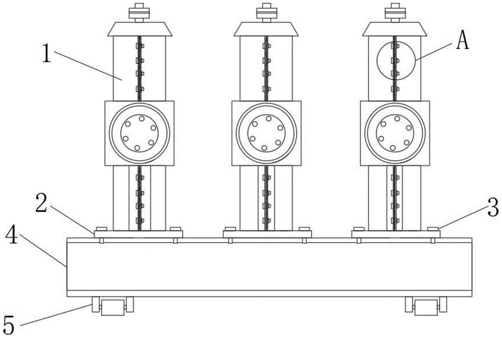
图1为本实用新型固封式户内高压真空断路器主视结构示意图;Fig. 1 is the front view structure schematic diagram of solid-sealed indoor high-voltage vacuum circuit breaker of the present invention;
图2为本实用新型固封式户内高压真空断路器测试结构示意图;FIG. 2 is a schematic view of the test structure of the solid-sealed indoor high-voltage vacuum circuit breaker of the present invention;
图3为本实用新型高压真空断路器未固封时主视结构示意图;Figure 3 is a schematic front view of the structure of the high-voltage vacuum circuit breaker of the present invention when it is not sealed;
图4为本实用新型高压真空断路器未固封时侧视结构示意图;Figure 4 is a schematic side view of the structure of the high-voltage vacuum circuit breaker of the present invention when it is not sealed;
图5为本实用新型中筒体立体结构示意图;5 is a schematic diagram of the three-dimensional structure of the cylinder in the utility model;
图6为图1中A处放大结构示意图;Fig. 6 is a schematic view of enlarged structure at A place in Fig. 1;
图中:1、真空断路器本体,101、绝缘支座,102、真空灭弧室,103、上接线端子,104、电流互感器,105、下接线端子,106、下接线端子,2、下接线端子,3、下接线端子,4、下接线端子,5、滚轮,6、操纵杆,7、筒体,8、连接耳,9、紧固螺栓,10、绝缘涂层,11、防护罩,12、绝缘垫,13、紧固螺母。In the figure: 1. Vacuum circuit breaker body, 101, insulating support, 102, vacuum interrupter, 103, upper terminal, 104, current transformer, 105, lower terminal, 106, lower terminal, 2, lower Terminal, 3, Lower terminal, 4, Lower terminal, 5, Roller, 6, Joystick, 7, Cylinder, 8, Connection lug, 9, Fastening bolt, 10, Insulation coating, 11, Protective cover , 12, insulating pad, 13, tighten the nut.
具体实施方式Detailed ways
下面将结合本实用新型实施例中的附图,对本实用新型实施例中的技术方案进行清楚、完整地描述,显然,所描述的实施例仅仅是本实用新型一部分实施例,而不是全部的实施例。基于本实用新型中的实施例,本领域普通技术人员在没有做出创造性劳动前提下所获得的所有其他实施例,都属于本实用新型保护的范围。The technical solutions in the embodiments of the present utility model will be clearly and completely described below with reference to the accompanying drawings in the embodiments of the present utility model. Obviously, the described embodiments are only a part of the embodiments of the present utility model, rather than all the implementations. example. Based on the embodiments of the present invention, all other embodiments obtained by those of ordinary skill in the art without creative work fall within the protection scope of the present invention.
实施例一Example 1
请参阅图1~6,一种固封式户内高压真空断路器,包括Please refer to Figures 1 to 6, a solid-sealed indoor high-voltage vacuum circuit breaker, including
真空断路器本体1,其设置有多个,且其下端固定安装有底座4,所述底座4的一侧侧壁上固定安装有操纵杆6;The vacuum
固封套组件,其设置在所述真空断路器本体1的外侧,通过设置固封套组件,能够对真空断路器本体1内部的真空灭弧室进行保护。The fixed envelope assembly is arranged on the outside of the vacuum
在本实用新型实施例中,所述真空断路器本体1由真空灭弧室102和绝缘支座101构成,所述绝缘支座101的上下两端均固接有真空灭弧室102,位于上端的所述真空灭弧室102的上侧设置有上接线端子103,所述绝缘支座101与真空灭弧室102的垂直侧侧壁上还固接有电流互感器104,所述电流互感器104的端部固接有下接线端子105,所述电流互感器104的下端固接有绝缘子106,能够控制电路的通断,提高用电安全。In the embodiment of the present invention, the vacuum
在本实用新型实施例中,所述固封套组件由两个截面为半圆形的筒体7构成,每个所述筒体7的外侧侧壁上均固接有竖向设置的连接耳8,所述连接耳8上贯穿设置有多个螺纹孔,且螺纹孔内螺纹设置有紧固螺栓9,所述紧固螺栓9上螺纹设置有紧固螺母13,两个所述筒体7通过紧固螺栓9与紧固螺母13之间的配合作用进行固定,安装方式简单,通过设置固封套组件,方便对真空灭弧室102进行保护,避免其受外界环境所影响,提高其使用寿命。In the embodiment of the present invention, the sealing sleeve assembly is composed of two
在本实用新型实施例中,所述电流互感器104和绝缘子106的外侧均设置有防护罩11,能够对二者进行保护。In the embodiment of the present invention, the outer sides of the
实施例二
请参阅图1~6,一种固封式户内高压真空断路器,包括Please refer to Figures 1 to 6, a solid-sealed indoor high-voltage vacuum circuit breaker, including
真空断路器本体1,其设置有多个,且其下端固定安装有底座4,所述底座4的一侧侧壁上固定安装有操纵杆6;The vacuum
固封套组件,其设置在所述真空断路器本体1的外侧,通过设置固封套组件,能够对真空断路器本体1内部的真空灭弧室进行保护。The fixed envelope assembly is arranged on the outside of the vacuum
在本实用新型实施例中,每个所述真空断路器本体1的下侧均固接有安装板2,所述安装板2的两侧贯穿设置有紧固螺钉3,所述真空断路器本体1通过紧固螺钉3固接在所述底座4的上表面,方便对真空断路器本体1进行拆卸,为后期维修更换提供方便。In the embodiment of the present invention, a
在本实用新型实施例中,所述底座4的下表面四角处固定安装有滚轮5,方便将该真空断路器本体1推入到控制柜内没有控制柜电路进行连接,操作方便。In the embodiment of the present invention, the four corners of the lower surface of the
在本实用新型实施例中,所述底座4的表面设置有绝缘涂层,能够在接电时,避免用电泄露对操作人员造成伤害。In the embodiment of the present invention, the surface of the
在本实用新型实施例中,两个所述筒体7的连接处固定设置有绝缘垫12,且筒体7的内壁上设置有绝缘涂层10,避免高压电流穿透筒体7,提高使用安全性。In the embodiment of the present invention, an insulating pad 12 is fixed at the connection of the two
工作原理:在使用该种固封式户内高压真空断路器时,首先将真空断路器本体1通过紧固螺钉3固接在底座4的上表面,然后在真空灭弧室102的外侧进行固封,将两个筒体7放置在真空灭弧室102的外侧,然后通过紧固螺栓9与紧固螺母13之间的配合作用对其进行固定,安装方式简单,通过设置固封套组件,方便对真空灭弧室102进行保护,避免其受外界环境所影响,提高其使用寿命,然后通过操纵杆6推动底座4移动,在滚轮5的滚动作用下,可以轻松地将该真空断路器与控制柜进行连接,在使用时,由于在筒体7的连接处固定设置有绝缘垫12,且筒体7的内壁上设置有绝缘涂层10,因此能够有效避免高压电流穿透筒体7,提高使用安全性。Working principle: When using this kind of solid-sealed indoor high-voltage vacuum circuit breaker, firstly fix the vacuum
此外,应当理解,虽然本说明书按照实施方式加以描述,但并非每个实施方式仅包含一个独立的技术方案,说明书的这种叙述方式仅仅是为清楚起见,本领域技术人员应当将说明书作为一个整体,各实施例中的技术方案也可以经适当组合,形成本领域技术人员可以理解的其他实施方式。In addition, it should be understood that although this specification is described in terms of embodiments, not each embodiment only includes an independent technical solution, and this description in the specification is only for the sake of clarity, and those skilled in the art should take the specification as a whole , the technical solutions in each embodiment can also be appropriately combined to form other implementations that can be understood by those skilled in the art.
Claims (8)
Priority Applications (1)
| Application Number | Priority Date | Filing Date | Title |
|---|---|---|---|
| CN202220214313.7U CN217086457U (en) | 2022-01-26 | 2022-01-26 | Solid-sealed indoor high-voltage vacuum circuit breaker |
Applications Claiming Priority (1)
| Application Number | Priority Date | Filing Date | Title |
|---|---|---|---|
| CN202220214313.7U CN217086457U (en) | 2022-01-26 | 2022-01-26 | Solid-sealed indoor high-voltage vacuum circuit breaker |
Publications (1)
| Publication Number | Publication Date |
|---|---|
| CN217086457U true CN217086457U (en) | 2022-07-29 |
Family
ID=82542729
Family Applications (1)
| Application Number | Title | Priority Date | Filing Date |
|---|---|---|---|
| CN202220214313.7U Expired - Fee Related CN217086457U (en) | 2022-01-26 | 2022-01-26 | Solid-sealed indoor high-voltage vacuum circuit breaker |
Country Status (1)
| Country | Link |
|---|---|
| CN (1) | CN217086457U (en) |
-
2022
- 2022-01-26 CN CN202220214313.7U patent/CN217086457U/en not_active Expired - Fee Related
Similar Documents
| Publication | Publication Date | Title |
|---|---|---|
| CN108493035A (en) | Disconnecting switch equipped with arc initiation device | |
| CN201682181U (en) | 10kV contact box of 4000 A | |
| CN215934276U (en) | 35kV inflatable switch cabinet | |
| CN207868675U (en) | A kind of insulated metal ring main unit | |
| CN205212366U (en) | Long generating line section of thick bamboo inner conductor strutting arrangement | |
| CN211062642U (en) | High-voltage load switch | |
| CN211907316U (en) | Outdoor high-voltage vacuum circuit breaker | |
| CN113161912B (en) | Uninterrupted maintenance device for high-voltage isolating switch operating mechanism | |
| CN206237027U (en) | Improved 10kV American box-type transformer with binocular through-holes and protective cover | |
| CN213304920U (en) | Ultrahigh-voltage double-bus shell | |
| CN221008690U (en) | Insulation clamping plate of breaker for inflatable cabinet | |
| CN216902666U (en) | Vacuum circuit breaker of convenient maintenance | |
| CN206388635U (en) | A kind of high-pressure vacuum breaker with antivibration effect | |
| CN221927873U (en) | A high voltage isolating switch bracket | |
| CN205070354U (en) | Especially big electric current enclosed bus equipment | |
| CN217881309U (en) | High-voltage vacuum circuit breaker for power equipment convenient to equipment | |
| CN219553501U (en) | High-low voltage isolating switch | |
| CN204464165U (en) | an insulating cylinder | |
| CN218678040U (en) | Mounting structure for high-voltage power distribution cabinet | |
| CN216698214U (en) | Plateau type alternating current vacuum circuit breaker | |
| CN205140856U (en) | Vacuum circuit breaker of safe pressure release | |
| CN216902669U (en) | Vacuum circuit breaker with vacuum degree monitoring function | |
| CN223065424U (en) | Lightning stroke early warning device for power transmission line network | |
| CN215578333U (en) | An electrical high-voltage isolation switch wire connection structure | |
| CN204668232U (en) | A kind of insulated tube holder assembly for vacuum circuit-breaker |
Legal Events
| Date | Code | Title | Description |
|---|---|---|---|
| GR01 | Patent grant | ||
| GR01 | Patent grant | ||
| CF01 | Termination of patent right due to non-payment of annual fee | ||
| CF01 | Termination of patent right due to non-payment of annual fee |
Granted publication date: 20220729 |