CN217072742U - Forming device is used in graphite crucible production - Google Patents
Forming device is used in graphite crucible production Download PDFInfo
- Publication number
- CN217072742U CN217072742U CN202220870594.1U CN202220870594U CN217072742U CN 217072742 U CN217072742 U CN 217072742U CN 202220870594 U CN202220870594 U CN 202220870594U CN 217072742 U CN217072742 U CN 217072742U
- Authority
- CN
- China
- Prior art keywords
- die holder
- graphite crucible
- side die
- hydraulic cylinder
- transverse plate
- Prior art date
- Legal status (The legal status is an assumption and is not a legal conclusion. Google has not performed a legal analysis and makes no representation as to the accuracy of the status listed.)
- Active
Links
- OKTJSMMVPCPJKN-UHFFFAOYSA-N Carbon Chemical compound [C] OKTJSMMVPCPJKN-UHFFFAOYSA-N 0.000 title claims abstract description 30
- 229910002804 graphite Inorganic materials 0.000 title claims abstract description 30
- 239000010439 graphite Substances 0.000 title claims abstract description 30
- 238000004519 manufacturing process Methods 0.000 title claims abstract description 15
- 239000007788 liquid Substances 0.000 claims abstract description 37
- 239000003795 chemical substances by application Substances 0.000 claims abstract description 21
- 238000000465 moulding Methods 0.000 claims description 11
- 238000003860 storage Methods 0.000 claims description 8
- 238000000748 compression moulding Methods 0.000 abstract description 11
- 239000002994 raw material Substances 0.000 abstract description 9
- 238000007493 shaping process Methods 0.000 abstract description 4
- 239000003973 paint Substances 0.000 abstract 1
- 238000000034 method Methods 0.000 description 7
- 238000001816 cooling Methods 0.000 description 2
- 230000007547 defect Effects 0.000 description 2
- 239000006082 mold release agent Substances 0.000 description 2
- 239000000243 solution Substances 0.000 description 2
- 235000017166 Bambusa arundinacea Nutrition 0.000 description 1
- 235000017491 Bambusa tulda Nutrition 0.000 description 1
- 241001330002 Bambuseae Species 0.000 description 1
- 235000015334 Phyllostachys viridis Nutrition 0.000 description 1
- 239000011425 bamboo Substances 0.000 description 1
- 230000009286 beneficial effect Effects 0.000 description 1
- 238000005266 casting Methods 0.000 description 1
- 238000003889 chemical engineering Methods 0.000 description 1
- 238000007906 compression Methods 0.000 description 1
- 238000010438 heat treatment Methods 0.000 description 1
- 238000005272 metallurgy Methods 0.000 description 1
- 238000012986 modification Methods 0.000 description 1
- 230000004048 modification Effects 0.000 description 1
- 239000011550 stock solution Substances 0.000 description 1
- 239000000126 substance Substances 0.000 description 1
- 230000001360 synchronised effect Effects 0.000 description 1
Images



Landscapes
- Ceramic Products (AREA)
Abstract
The utility model discloses a forming device for graphite crucible production, which comprises a vertically and fixedly arranged bracket, wherein a first hydraulic cylinder is fixedly arranged at the upper end of the bracket, an upper die base is fixedly arranged at the lower end of a rod body of the first hydraulic cylinder, a transverse plate is arranged in the middle of the bracket, and a second hydraulic cylinder is arranged on the lower surface of the transverse plate; further comprising: the side die holder is fixedly arranged on the upper surface of the transverse plate, a bottom die is arranged on the inner side of the side die holder, and the bottom die is fixedly arranged at the upper end of the rod body of the second hydraulic cylinder; and the piston cylinder is fixedly arranged on the lower surface of the transverse plate and used for conveying the release agent, and a liquid suction pipe and a liquid discharge pipe are respectively connected between the piston cylinder and the side die holder and between the piston cylinder and the bottom die. This forming device is used in graphite crucible production can be convenient stable carry out compression moulding to the raw materials, and can paint the release agent to the mould inner wall is automatic in the use, has improved the convenience and the integrality of follow-up shaping drawing of patterns.
Description
Technical Field
The utility model relates to a graphite crucible production technical field specifically is a forming device is used in graphite crucible production.
Background
The graphite crucible is a special crucible processed by utilizing graphite raw materials, has good thermal conductivity and high temperature resistance, has small thermal expansion coefficient in the high-temperature use process, has certain strain resistance to rapid heating and rapid cooling, and has excellent chemical stability, so the graphite crucible is widely applied to industries such as metallurgy, casting, machinery, chemical engineering and the like, and a forming device is required to be used in the production process of the graphite crucible, but the existing forming device still has some defects.
The forming device for producing the existing graphite crucible mostly adopts a compression molding mode to shape the crucible, and needs to apply larger pressure to raw materials in the compression process, so as to ensure the strength of the formed graphite crucible, but the forming device for producing the existing graphite crucible has a fixed structure, is inconvenient to carry out convenient and complete demolding on a formed product after the compression molding is finished, and has certain use defects.
Therefore, we have proposed a molding apparatus for graphite crucible production in order to solve the above-mentioned problems.
Disclosure of Invention
An object of the utility model is to provide a forming device is used in graphite crucible production to solve the forming device fixed structure for graphite crucible production on the existing market that above-mentioned background art provided, inconvenient problem of carrying out convenient complete drawing of patterns to the shaping product after the compression moulding is accomplished.
In order to achieve the above object, the utility model provides a following technical scheme: a forming device for producing a graphite crucible comprises a vertically and fixedly placed support, wherein a first hydraulic cylinder is fixedly installed at the upper end of the support, an upper die base is fixedly installed at the lower end of a rod body of the first hydraulic cylinder, a transverse plate is installed in the middle of the support, and a second hydraulic cylinder is installed on the lower surface of the transverse plate;
further comprising:
the side die holder is fixedly arranged on the upper surface of the transverse plate, a bottom die is arranged on the inner side of the side die holder, and the bottom die is fixedly arranged at the upper end of the rod body of the second hydraulic cylinder;
and the piston cylinder is fixedly arranged on the lower surface of the transverse plate and used for conveying the release agent, and a liquid suction pipe and a liquid discharge pipe are respectively connected between the piston cylinder and the side die holder and between the piston cylinder and the bottom die.
Preferably, the central axes of the upper die base, the side die base and the bottom die are coincident, and the diameter of the upper end of the upper die base is larger than the inner diameter of the side die base.
By adopting the technical scheme, the upper die base can be matched with the bottom die to extrude the graphite raw material on the inner side of the side die base in the downward moving process of the upper die base, so that the compression molding of the crucible is realized, and the molding efficiency is improved.
Preferably, the side die holder is arranged in a round tube-shaped structure, a liquid storage bin is arranged inside the side die holder, and heat conduction fins are uniformly arranged on the inner wall of the liquid storage bin.
Through adopting above-mentioned technical scheme, can save the release agent through the stock solution storehouse, and the heat conduction fin can effectively promote the heat transfer of side die holder and its inside release agent for the release agent can absorb the heat that the compression molding in-process produced, and then realizes effectively cooling to the shaping crucible, does benefit to the stable shaping of crucible.
Preferably, the side wall of the bottom die is attached to the inner wall of the side die holder, and the bottom die and the side die holder form a lifting structure.
By adopting the technical scheme, after the crucible is molded, the second hydraulic cylinder can be controlled to push the bottom die to move upwards along the inner wall of the side die base, so that the molded crucible can be conveniently pushed out of the side die base, and convenient demolding is further realized.
Preferably, push rods are arranged on the lower surface of the bottom die in the circumferential direction at equal angles, the push rods and the piston cylinder form a telescopic structure, a piston sheet is fixedly mounted at the lower end of each push rod, and meanwhile a liquid suction pipe and a liquid discharge pipe connected to the lower end of the piston cylinder are of a one-way circulation structure.
Through adopting above-mentioned technical scheme for the die block removes the in-process, and the push rod can drive the piston piece and carry out synchronous movement, makes the piston section of thick bamboo utilize the pipette to draw the release agent in the side die holder automatically, and discharges through the fluid-discharge tube, realizes the transport of release agent.
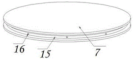
Preferably, the side wall of the bottom die is provided with an accommodating groove with an annular structure, liquid holes are formed in the side wall of the accommodating groove at equal angles in the circumferential direction, and the liquid holes are communicated with a liquid discharge pipe.
By adopting the technical scheme, the mold release agent sucked in the piston cylinder can be conveyed to the containing groove in the downward moving process of the bottom mold, so that the mold release agent can be automatically coated on the inner side of the side mold base in the moving process of the bottom mold, and the subsequent molding demolding work is facilitated.
Compared with the prior art, the beneficial effects of the utility model are that: the forming device for producing the graphite crucible can be used for conveniently and stably performing compression molding on raw materials, and can be used for automatically smearing a release agent on the inner wall of a mold in the using process, so that the convenience and the integrity of subsequent molding and demolding are improved, and the specific content is as follows;
1. the upper die base, the side die base and the bottom die are arranged, the lower pressure of the upper die base is controlled, the bottom die can be matched with the graphite raw material on the inner side of the side die base to extrude, and the release agent contained in the side die base can efficiently cool a finished product, so that efficient and stable compression molding is realized;
2. the bottom die, the piston cylinder and the liquid holes are arranged, after compression molding, the bottom die is controlled to move upwards, the finished crucible on the inner side of the side die base can be pushed upwards, demolding of finished products is facilitated, and when the bottom die moves downwards, the piston cylinder can discharge the demolding agent sucked by the piston cylinder through the liquid holes, so that automatic smearing of the demolding agent is achieved, and further the subsequent demolding efficiency of the finished products is improved.
Drawings
FIG. 1 is a schematic view of the main sectional structure of the present invention;
FIG. 2 is a schematic view of the piston cylinder mounting structure of the present invention;
FIG. 3 is a schematic view of the structure of the cross plate of the present invention;
fig. 4 is a schematic view of the three-dimensional structure of the bottom die of the present invention;
fig. 5 is the schematic view of the sectional structure of the side die holder of the present invention.
In the figure: 1. a support; 2. a first hydraulic cylinder; 3. an upper die holder; 4. a transverse plate; 5. a side die holder; 6. a second hydraulic cylinder; 7. bottom die; 8. a piston cylinder; 9. a liquid storage bin; 10. a heat conductive fin; 11. a push rod; 12. a piston plate; 13. a pipette; 14. a liquid discharge pipe; 15. a containing groove; 16. and (4) liquid holes.
Detailed Description
The technical solutions in the embodiments of the present invention will be described clearly and completely with reference to the accompanying drawings in the embodiments of the present invention, and it is obvious that the described embodiments are only some embodiments of the present invention, not all embodiments. Based on the embodiments in the present invention, all other embodiments obtained by a person skilled in the art without creative work belong to the protection scope of the present invention.
Referring to fig. 1-5, the present invention provides a technical solution: a molding device for producing a graphite crucible comprises a support 1 which is vertically and fixedly placed, wherein a first hydraulic cylinder 2 is fixedly installed at the upper end of the support 1, an upper die base 3 is fixedly installed at the lower end of a rod body of the first hydraulic cylinder 2, a transverse plate 4 is installed in the middle of the support 1, and a second hydraulic cylinder 6 is installed on the lower surface of the transverse plate 4;
further comprising: the side die holder 5 is fixedly arranged on the upper surface of the transverse plate 4, a bottom die 7 is arranged on the inner side of the side die holder 5, and the bottom die 7 is fixedly arranged at the upper end of a rod body of the second hydraulic cylinder 6; and the piston cylinder 8 is fixedly arranged on the lower surface of the transverse plate 4 and used for conveying the release agent, and a liquid suction pipe 13 and a liquid discharge pipe 14 are respectively connected between the piston cylinder 8 and the side die base 5 and the bottom die 7.
The central axes of the upper die base 3, the side die base 5 and the bottom die 7 are coincident, and the diameter of the upper end of the upper die base 3 is larger than the inner diameter of the side die base 5. The side die holder 5 is arranged in a round tube-shaped structure, the liquid storage bin 9 is arranged inside the side die holder 5, and heat conduction fins 10 are uniformly arranged on the inner wall of the liquid storage bin 9. The side wall of the bottom die 7 is attached to the inner wall of the side die holder 5, and the bottom die 7 and the side die holder 5 form a lifting structure, as shown in fig. 1 and fig. 5, the graphite raw material to be processed is poured into the inner side of the side die holder 5, then the first hydraulic cylinder 2 is started, so that the first hydraulic cylinder 2 pushes the upper die holder 3 to move downwards, at this time, the upper die holder 3 can gradually move to the inner side of the side die holder 5, so that compression molding of the raw material in the inner side of the side die holder 5 is realized, meanwhile, the release agent in the inner side of the side die holder 5 can effectively cool the formed crucible, after molding, the upper die holder 3 is controlled to move upwards, then the second hydraulic cylinder 6 is started, so that the bottom die 7 is pushed to move upwards, so that the formed crucible can be pushed out of the side die holder 5, and demolding is realized.
The working principle is as follows: when the forming device for producing the graphite crucible is used, firstly, as shown in fig. 1 to 5, graphite raw materials to be processed are poured into the inner side of the side die holder 5, the upper die holder 3 is controlled to move downwards to realize compression molding, meanwhile, the release agent on the inner side of the side die holder 5 can effectively cool the formed crucible, then the upper die holder 3 is controlled to reset, the bottom die 7 is controlled to move upwards to push out a finished product to realize demolding, and when the bottom die 7 moves downwards to reset, the piston cylinder 8 can utilize the liquid discharge pipe 14 and the liquid hole 16 to extrude the release agent into the accommodating groove 15, so that the release agent is uniformly coated on the inner wall of the side die holder 5, and a series of work is completed.
Those not described in detail in this specification are within the skill of the art.
Although the present invention has been described in detail with reference to the foregoing embodiments, it will be apparent to those skilled in the art that modifications may be made to the embodiments or portions thereof without departing from the spirit and scope of the invention.
Claims (6)
1. A forming device for producing a graphite crucible comprises a support (1) which is vertically and fixedly placed, wherein a first hydraulic cylinder (2) is fixedly installed at the upper end of the support (1), an upper die holder (3) is fixedly installed at the lower end of a rod body of the first hydraulic cylinder (2), a transverse plate (4) is installed in the middle of the support (1), and a second hydraulic cylinder (6) is installed on the lower surface of the transverse plate (4);
it is characterized by also comprising:
the side die holder (5) is fixedly arranged on the upper surface of the transverse plate (4), a bottom die (7) is arranged on the inner side of the side die holder (5), and the bottom die (7) is fixedly arranged at the upper end of the rod body of the second hydraulic cylinder (6);
and the piston cylinder (8) is fixedly arranged on the lower surface of the transverse plate (4) and used for conveying the release agent, and a liquid suction pipe (13) and a liquid discharge pipe (14) are respectively connected between the piston cylinder (8) and the side die holder (5) and between the piston cylinder and the bottom die (7).
2. The molding apparatus for graphite crucible production as set forth in claim 1, wherein: the central axes of the upper die holder (3), the side die holder (5) and the bottom die (7) are coincident, and the diameter of the upper end of the upper die holder (3) is larger than the inner diameter of the side die holder (5).
3. The molding apparatus for graphite crucible production as set forth in claim 1, wherein: the side die holder (5) is arranged in a round tube-shaped structure, a liquid storage bin (9) is arranged inside the side die holder (5), and heat conduction fins (10) are uniformly arranged on the inner wall of the liquid storage bin (9).
4. The molding apparatus for graphite crucible production as set forth in claim 1, wherein: the lateral wall of die block (7) is laminated on the inner wall of side die holder (5), just die block (7) and side die holder (5) constitute elevation structure.
5. The molding apparatus for graphite crucible production as set forth in claim 1, wherein: the lower surface circumference of die block (7) is provided with push rod (11) with the angle such as, just push rod (11) and piston cylinder (8) constitute extending structure, and the lower extreme fixed mounting of push rod (11) has piston piece (12), simultaneously pipette (13), fluid-discharge tube (14) that piston cylinder (8) lower extreme is connected are one-way circulation structure.
6. The molding apparatus for graphite crucible production as set forth in claim 1, wherein: the lateral wall of die block (7) is seted up accommodating groove (15) of loop configuration, just the lateral wall circumference of accommodating groove (15) is equalled and is seted up liquid hole (16), and liquid hole (16) are linked together with fluid-discharge tube (14).
Priority Applications (1)
| Application Number | Priority Date | Filing Date | Title |
|---|---|---|---|
| CN202220870594.1U CN217072742U (en) | 2022-04-15 | 2022-04-15 | Forming device is used in graphite crucible production |
Applications Claiming Priority (1)
| Application Number | Priority Date | Filing Date | Title |
|---|---|---|---|
| CN202220870594.1U CN217072742U (en) | 2022-04-15 | 2022-04-15 | Forming device is used in graphite crucible production |
Publications (1)
| Publication Number | Publication Date |
|---|---|
| CN217072742U true CN217072742U (en) | 2022-07-29 |
Family
ID=82498899
Family Applications (1)
| Application Number | Title | Priority Date | Filing Date |
|---|---|---|---|
| CN202220870594.1U Active CN217072742U (en) | 2022-04-15 | 2022-04-15 | Forming device is used in graphite crucible production |
Country Status (1)
| Country | Link |
|---|---|
| CN (1) | CN217072742U (en) |
Cited By (2)
| Publication number | Priority date | Publication date | Assignee | Title |
|---|---|---|---|---|
| CN115742026A (en) * | 2022-09-08 | 2023-03-07 | 吉林龙昌新能源有限责任公司 | Mechanical cutting device for processing graphite crucible |
| CN117863320A (en) * | 2024-03-13 | 2024-04-12 | 淄博华鸣新材料有限公司 | A graphite crucible pressing and forming device |
-
2022
- 2022-04-15 CN CN202220870594.1U patent/CN217072742U/en active Active
Cited By (4)
| Publication number | Priority date | Publication date | Assignee | Title |
|---|---|---|---|---|
| CN115742026A (en) * | 2022-09-08 | 2023-03-07 | 吉林龙昌新能源有限责任公司 | Mechanical cutting device for processing graphite crucible |
| CN115742026B (en) * | 2022-09-08 | 2023-05-26 | 吉林龙昌新能源有限责任公司 | Mechanical cutting device for graphite crucible processing |
| CN117863320A (en) * | 2024-03-13 | 2024-04-12 | 淄博华鸣新材料有限公司 | A graphite crucible pressing and forming device |
| CN117863320B (en) * | 2024-03-13 | 2024-06-14 | 淄博华鸣新材料有限公司 | Graphite crucible compression molding device |
Similar Documents
| Publication | Publication Date | Title |
|---|---|---|
| CN218928147U (en) | Quick shedder of graphite crucible production usefulness | |
| CN112297193B (en) | Foamed ceramic plate production mould | |
| CN111729940A (en) | Copper bar production and manufacturing stretching equipment and copper bar production and manufacturing stretching process | |
| CN222919639U (en) | Powder material metallurgical die with efficient heat conduction and heat dissipation | |
| CN101786320B (en) | PTFE molding pusher for easy core replacement | |
| CN210477652U (en) | Plastic forming die with adjustable cavity | |
| CN209599918U (en) | A graphite tube forming device | |
| CN211941962U (en) | Extruder for corrugated pipe production | |
| CN214872109U (en) | Rapid molding development equipment for plastic products | |
| CN216068551U (en) | But device of moulding plastics is used in carbon fiber material processing of fast demoulding | |
| CN213382888U (en) | Combined plastic pipe extrusion die | |
| CN214991424U (en) | Handicraft candle batch forming device | |
| CN211518247U (en) | Plastic mould demoulding structure | |
| CN212917584U (en) | Extrusion forming die for valve plate processing | |
| CN212219261U (en) | Flanging device for polytetrafluoroethylene pipe | |
| CN210586443U (en) | Capillary tube making machine | |
| CN210651580U (en) | Crowded mouthful frock of pipe fitting | |
| CN210208119U (en) | Forming machine for producing heater | |
| CN222521899U (en) | Plastic injection mold with high cooling molding efficiency | |
| CN224103352U (en) | Forming die for pipeline model based on 3D prints | |
| CN213972454U (en) | Cooling and shaping integrated wood-plastic plate extrusion die | |
| CN220499729U (en) | Demolding device for composite material product | |
| CN220946330U (en) | Hollow backing plate raw material processing equipment | |
| CN220497359U (en) | Aluminum extrusion die with DLC coating on surface | |
| CN221136573U (en) | Extrusion die |
Legal Events
| Date | Code | Title | Description |
|---|---|---|---|
| GR01 | Patent grant | ||
| GR01 | Patent grant |