CN217070967U - High-precision fixed-length cutting device for stainless steel pipes - Google Patents
High-precision fixed-length cutting device for stainless steel pipes Download PDFInfo
- Publication number
- CN217070967U CN217070967U CN202123019700.XU CN202123019700U CN217070967U CN 217070967 U CN217070967 U CN 217070967U CN 202123019700 U CN202123019700 U CN 202123019700U CN 217070967 U CN217070967 U CN 217070967U
- Authority
- CN
- China
- Prior art keywords
- cutting
- stainless steel
- plate
- fixed
- steel pipe
- Prior art date
- Legal status (The legal status is an assumption and is not a legal conclusion. Google has not performed a legal analysis and makes no representation as to the accuracy of the status listed.)
- Active
Links
- 238000005520 cutting process Methods 0.000 title claims abstract description 96
- 229910001220 stainless steel Inorganic materials 0.000 title claims abstract description 38
- 239000010935 stainless steel Substances 0.000 title claims abstract description 38
- 230000000694 effects Effects 0.000 claims description 9
- 238000001125 extrusion Methods 0.000 claims description 7
- 230000001681 protective effect Effects 0.000 claims description 3
- 208000027418 Wounds and injury Diseases 0.000 abstract description 4
- 230000006378 damage Effects 0.000 abstract description 4
- 208000014674 injury Diseases 0.000 abstract description 4
- 229910000831 Steel Inorganic materials 0.000 description 24
- 239000010959 steel Substances 0.000 description 24
- 238000000034 method Methods 0.000 description 2
- 238000003860 storage Methods 0.000 description 2
- 230000004075 alteration Effects 0.000 description 1
- 230000009286 beneficial effect Effects 0.000 description 1
- 230000006835 compression Effects 0.000 description 1
- 238000007906 compression Methods 0.000 description 1
- 238000010276 construction Methods 0.000 description 1
- 238000004519 manufacturing process Methods 0.000 description 1
- 238000012986 modification Methods 0.000 description 1
- 230000004048 modification Effects 0.000 description 1
- 238000006467 substitution reaction Methods 0.000 description 1
Images



Landscapes
- Sawing (AREA)
Abstract
The utility model relates to a high-precision fixed-length cutting device for stainless steel pipes, which comprises a base, wherein the surface of the base is fixedly provided with a cutting table, the surface of the cutting table is provided with a positioning mechanism, the surface of one end of the cutting table is fixedly provided with a fixing mechanism, the upper part of the base is provided with a cutting mechanism through two supporting frames, the utility model has reasonable structure, the positioning mechanism can measure the length of the stainless steel pipe at any time by matching with a scale bar on the side surface of the cutting table, the practicability is improved, the positioning mechanism can also fix the stainless steel pipe, the stainless steel pipe is prevented from shaking, the design of the fixing mechanism can fix the front end of the stainless steel pipe, the stainless steel pipe is prevented from deviating, the cutting work is wrong, the movable design of the cutting mechanism is convenient for matching with the positioning mechanism to cut, and the design of a baffle can prevent sparks from splashing when the stainless steel pipe is cut, avoid causing the injury to the staff.
Description
Technical Field
The utility model relates to a cutting device especially relates to a device that is used for carrying out high accuracy fixed length cutting to nonrust steel pipe, belongs to nonrust steel pipe technical field.
Background
At present, stainless steel pipes are one of the standard workpieces frequently used in the fields of equipment manufacturing, field construction and the like. For the convenience of transportation and storage, the stainless steel pipe needs to be cut after being formed by drawing. In order to match different customers or different storage environments, when the stainless steel pipes are cut, the lengths of the stainless steel pipes need to be measured to ensure matching, and the cut stainless steel pipes are all the same in length to ensure consistency. However, in the process of cutting by the conventional cutting machine, the cutting accuracy of the steel pipe is easily affected due to disturbance, and the cutting quality of the steel pipe is further affected. Therefore, a cutting device capable of solving the above problems is needed.
SUMMERY OF THE UTILITY MODEL
An object of the utility model is to overcome the aforesaid not enough, provide a high accuracy fixed length cutting device of nonrust steel pipe, it can measure and fix the steel pipe to guarantee its cutting accuracy.
In order to achieve the above object, the utility model provides a following technical scheme:
the utility model provides a high accuracy fixed length cutting device of nonrust steel pipe, includes the base, the fixed surface of base is provided with the cutting bed, the surface of cutting bed is provided with positioning mechanism, the one end fixed surface of cutting bed is provided with fixed establishment, the top of base is provided with cutting mechanism through two support frames, positioning mechanism includes first backing plate, first stripper plate, spring, handle, slip lug and first rubber pad, fixed establishment includes mainboard, second backing plate, second stripper plate, threaded rod, bearing and second rubber pad, cutting mechanism includes the lantern ring, telescopic link, lag and cutting knife.
Preferably, a connecting plate is fixedly connected between the two support frames, and the surface of the connecting plate is movably sleeved with the cutting mechanism.
Preferably, the one end surface of cutting bed is provided with the cushion through tenon fourth of twelve earthly branches structure, the slide rail has all been seted up to the both sides of cutting bed, the both sides of cutting bed all are equipped with the scale strip.
Preferably, the surface of the base is movably provided with two baffles through slots, and the slots are arranged on the side surfaces of the supporting frame.
Preferably, the first backing plate passes through the slide rail activity set up in cutting bed surface, first stripper plate pass through the spring activity set up in first backing plate top, the handle is fixed set up in first stripper plate surface, the slip lug set up in first backing plate bottom both sides, the size and the position of slip lug all with the slide rail phase-match, first rubber pad fixed set up in first stripper plate bottom.
Preferably, the mainboard is fixed set up in cutting bed surface one end, the second backing plate set up in the mainboard side, the second stripper plate passes through the threaded rod activity set up in second backing plate top, the threaded rod passes through bearing swing joint in second stripper plate surface, the second rubber pad is fixed set up in second stripper plate bottom.
Preferably, the sleeve is sleeved on the surface of the connecting plate, the telescopic rod is fixedly arranged at the bottom of the sleeve, the cutting knife is arranged at the bottom of the telescopic rod through the protective sleeve, and the cutting knife is positioned above the cutting table.
The utility model provides a high accuracy fixed length cutting device of nonrust steel pipe possesses following beneficial effect:
(1) the utility model discloses rational in infrastructure, the length of nonrust steel pipe can be measured at any time to the scale strip of positioning mechanism cooperation cutting bed side, promotes the practicality, and positioning mechanism also can fix nonrust steel pipe, prevents that nonrust steel pipe from rocking, and fixing mechanism's design can be fixed the front end of nonrust steel pipe, prevents that the skew from appearing in nonrust steel pipe, leads to cutting work mistake.
(2) The movable design of cutting mechanism is convenient for cooperate positioning mechanism to cut, and the spark when the design of baffle can prevent to cut nonrust steel pipe splashes, avoids causing the injury to the staff.
Drawings
Fig. 1 is a schematic view of the overall structure of a high-precision fixed-length cutting device for stainless steel pipes according to the present invention;
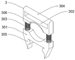
FIG. 2 is a schematic structural view of a positioning mechanism of a high-precision fixed-length cutting device for stainless steel pipes according to the present invention;
FIG. 3 is an enlarged view of the part A in FIG. 1 of the high-precision fixed-length cutting device for stainless steel pipes of the present invention;
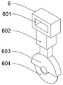
fig. 4 is a structural schematic view of a cutting mechanism of the high-precision fixed-length cutting device for stainless steel pipes of the present invention;
fig. 5 is a schematic view of the supporting frame structure of the present invention.
In the figure: 1. a base; 2. cutting table; 201. a slide rail; 202. a scale bar; 3. a positioning mechanism; 301. a first backing plate; 302. a first squeeze plate; 303. a spring; 304. a handle; 305. a sliding projection; 306. a first rubber pad; 4. a fixing mechanism; 401. a main board; 402. a second backing plate; 403. a second compression plate; 404. a threaded rod; 405. a bearing; 406. a second rubber pad; 5. a support frame; 501. a connecting plate; 502. a slot; 6. a cutting mechanism; 601. a collar; 602. a telescopic rod; 603. a protective sleeve; 604. a cutting knife; 7. a mortise and tenon joint structure; 8. cushion blocks; 9. and a baffle plate.
Detailed Description
Referring to fig. 1-5, the utility model relates to a high accuracy fixed length cutting device of stainless steel pipe, including base 1, base 1's fixed surface is provided with cutting table 2, the surface of cutting table 2 is provided with positioning mechanism 3, the one end fixed surface of cutting table 2 is provided with fixed establishment 4, base 1's top is provided with cutting mechanism 6 through two support frames 5, positioning mechanism 3 includes first backing plate 301, first stripper plate 302, spring 303, handle 304, sliding lug 305 and first rubber pad 306, fixed establishment 4 includes mainboard 401, second backing plate 402, second stripper plate 403, threaded rod 404, bearing 405 and second rubber pad 406, cutting mechanism 6 includes the lantern ring 601, telescopic link 602, lag 603 and cutting knife 604. A connecting plate 501 is fixedly connected between the two supporting frames 5, and the cutting mechanism 6 is movably sleeved on the surface of the connecting plate 501.
Simultaneously, the one end surface of cutting bed 2 is provided with cushion 8 through tenon fourth of twelve earthly branches structure 7, and slide rail 201 has all been seted up to the both sides of cutting bed 2, and the both sides of cutting bed 2 all are equipped with scale bar 202, and the length of nonrust steel pipe can be measured at any time to the scale bar 202 of cutting bed 2 side, promotes the practicality.
The surface of base 1 is provided with two baffles 9 through slot 502 activity, and slot 502 is seted up in support frame 5 side, and baffle 9 can be installed through inserting slot 502 is inside, and the spark when baffle 9's design can prevent to cut nonrust steel pipe splashes, avoids causing the injury to the staff.
Connecting plate 501 surface is located to lantern ring 601 cover, and telescopic link 602 is fixed to be set up in lantern ring 601 bottom, and cutting knife 604 sets up in telescopic link 602 bottom through lag 603, and cutting knife 604 is located cutting bed 2 top, and the position of sliding lantern ring 601 to cutting mechanism 6 is adjusted according to positioning mechanism 3's position, and telescopic link 602 drives cutting knife 604 and pushes down and cuts nonrust steel pipe, and the movable design of cutting mechanism 6 is convenient for cooperate positioning mechanism 3 to cut.
The utility model discloses a working process does: the stainless steel pipe is placed on the surface of the cushion block 8, the positioning mechanism 3 is moved in the sliding rail 201 according to the required length, the length is confirmed by matching with the scale bar 202, the sliding rail 201 and the sliding bump 305 are designed to facilitate the movement of the positioning mechanism 3, the first extrusion plate 302 is pulled up by using the handle 304, the stainless steel pipe is placed on the surface of the first base plate 301, the handle 304 is loosened, the stainless steel pipe is clamped and fixed by the first extrusion plate 302 due to the elasticity of the spring 303, the friction force of the first extrusion plate 302 can be improved by the first rubber pad 306, the fixing capacity is enhanced, the positioning mechanism 3 can also fix the stainless steel pipe to prevent the stainless steel pipe from shaking, then the front end of the stainless steel pipe is placed on the surface of the second base plate 402, the threaded rod 404 is rotated to drive the second extrusion plate 403 to press down to fix the stainless steel pipe, the front end of the stainless steel pipe can be fixed by the design of the fixing mechanism 4, prevent that the skew from appearing in the nonrust steel pipe, lead to cutting work mistake, the position slip lantern ring 601 according to positioning mechanism 3 adjusts cutting mechanism 6's position, telescopic link 602 drives cutting knife 604 and pushes down and cuts nonrust steel pipe, cutting mechanism 6's movable design is convenient for cooperate positioning mechanism 3 to cut, during the cutting, insert inside slot 502 with baffle 9, the spark when baffle 9's design can prevent to cut nonrust steel pipe splashes, avoid causing the injury to the staff.
Although embodiments of the present invention have been shown and described, it will be appreciated by those skilled in the art that changes, modifications, substitutions and alterations can be made in these embodiments without departing from the principles and spirit of the invention, the scope of which is defined in the appended claims and their equivalents.
Claims (7)
1. The utility model provides a high accuracy fixed length cutting device of stainless steel pipe, a serial communication port, including base (1), the fixed surface of base (1) is provided with cutting table (2), the surface of cutting table (2) is provided with positioning mechanism (3), the one end fixed surface of cutting table (2) is provided with fixed establishment (4), the top of base (1) is provided with cutting mechanism (6) through two support frames (5), positioning mechanism (3) include first backing plate (301), first stripper plate (302), spring (303), handle (304), slip lug (305) and first rubber pad (306), fixed establishment (4) include mainboard (401), second backing plate (402), second stripper plate (403), threaded rod (404), bearing (405) and second rubber pad (406), cutting mechanism (6) are including lantern ring (601), rubber pad (406), The cutting device comprises a telescopic rod (602), a protective sleeve (603) and a cutting knife (604).
2. The high-precision fixed-length cutting device for the stainless steel pipes, according to claim 1, is characterized in that: two fixedly connected with connecting plate (501) between support frame (5), cutting mechanism (6) movable sleeve is located connecting plate (501) surface.
3. The high-precision fixed-length cutting device for the stainless steel pipes, according to claim 1, is characterized in that: the surface of one end of the cutting table (2) is provided with a cushion block (8) through a mortise and tenon structure (7), sliding rails (201) are arranged on two sides of the cutting table (2), and scale bars (202) are arranged on two sides of the cutting table (2).
4. The high-precision fixed-length cutting device for the stainless steel pipes, according to claim 1, is characterized in that: the surface of the base (1) is movably provided with two baffles (9) through slots (502), and the slots (502) are arranged on the side surfaces of the support frame (5).
5. A high precision fixed length cutting device for stainless steel pipes according to claim 3, characterized in that: first backing plate (301) pass through slide rail (201) activity set up in cutting table (2) surface, first stripper plate (302) through spring (303) activity set up in first backing plate (301) top, handle (304) are fixed set up in first stripper plate (302) surface, slip lug (305) set up in first backing plate (301) bottom both sides, the size and the position of slip lug (305) all with slide rail (201) phase-match, first rubber pad (306) fixed set up in first stripper plate (302) bottom.
6. The high-precision fixed-length cutting device for the stainless steel pipes, according to claim 1, is characterized in that: the main plate (401) is fixedly arranged at one end of the surface of the cutting table (2), the second base plate (402) is arranged on the side surface of the main plate (401), the second extrusion plate (403) is movably arranged above the second base plate (402) through the threaded rod (404), the threaded rod (404) is movably connected to the surface of the second extrusion plate (403) through the bearing (405), and the second rubber pad (406) is fixedly arranged at the bottom of the second extrusion plate (403).
7. The high-precision fixed-length cutting device for the stainless steel pipes, according to claim 2, is characterized in that: the lantern ring (601) is sleeved on the surface of the connecting plate (501), the telescopic rod (602) is fixedly arranged at the bottom of the lantern ring (601), the cutting knife (604) is arranged at the bottom of the telescopic rod (602) through the protecting sleeve (603), and the cutting knife (604) is positioned above the cutting table (2).
Priority Applications (1)
| Application Number | Priority Date | Filing Date | Title |
|---|---|---|---|
| CN202123019700.XU CN217070967U (en) | 2021-12-03 | 2021-12-03 | High-precision fixed-length cutting device for stainless steel pipes |
Applications Claiming Priority (1)
| Application Number | Priority Date | Filing Date | Title |
|---|---|---|---|
| CN202123019700.XU CN217070967U (en) | 2021-12-03 | 2021-12-03 | High-precision fixed-length cutting device for stainless steel pipes |
Publications (1)
| Publication Number | Publication Date |
|---|---|
| CN217070967U true CN217070967U (en) | 2022-07-29 |
Family
ID=82539418
Family Applications (1)
| Application Number | Title | Priority Date | Filing Date |
|---|---|---|---|
| CN202123019700.XU Active CN217070967U (en) | 2021-12-03 | 2021-12-03 | High-precision fixed-length cutting device for stainless steel pipes |
Country Status (1)
| Country | Link |
|---|---|
| CN (1) | CN217070967U (en) |
Cited By (1)
| Publication number | Priority date | Publication date | Assignee | Title |
|---|---|---|---|---|
| CN115319193A (en) * | 2022-10-13 | 2022-11-11 | 南通慧晶机械科技有限公司 | Cutting equipment to metal pipeline |
-
2021
- 2021-12-03 CN CN202123019700.XU patent/CN217070967U/en active Active
Cited By (1)
| Publication number | Priority date | Publication date | Assignee | Title |
|---|---|---|---|---|
| CN115319193A (en) * | 2022-10-13 | 2022-11-11 | 南通慧晶机械科技有限公司 | Cutting equipment to metal pipeline |
Similar Documents
| Publication | Publication Date | Title |
|---|---|---|
| CN213164249U (en) | Quick clamping type workstation for vertical lathe | |
| CN217618056U (en) | High-speed circular sawing machine for cutting raw materials for steel pipe production | |
| CN210755236U (en) | Milling machine boring and milling cutter disc device for machining torsion tube | |
| CN210791181U (en) | Portable manual paper cutting device | |
| CN217412657U (en) | Positioning and aligning device for manufacturing steel structure | |
| CN217530932U (en) | Hydraulic paper cutter for image-text binding | |
| CN214724639U (en) | A convenient clamping cutting device for bar processing | |
| CN212667013U (en) | An embossing device for a printing press | |
| CN212495756U (en) | Steel cutting device convenient to it is fixed | |
| CN212217807U (en) | Supporting device for machining large workpiece of boring and milling machine | |
| CN210967242U (en) | A height-adjustable slitter blade | |
| CN219563766U (en) | Supporting mechanism of cutting machine | |
| CN208133067U (en) | oil pipe cutting machine | |
| CN219772526U (en) | Non-woven fabrics cutting machine | |
| CN218555732U (en) | Lithium battery electrode plate cutting device | |
| CN220880647U (en) | Positioner is used in dysmorphism casing punching | |
| CN223277505U (en) | Anti-drop pick pressfitting instrument | |
| CN219666762U (en) | Safety protection device of cutting equipment | |
| CN212123564U (en) | Quick die change mechanism of cross cutting machine | |
| CN221416369U (en) | Adjustable fixing mechanism | |
| CN219357985U (en) | Perforating device of machinery spare and accessory parts | |
| CN214294008U (en) | Single bimodulus integrated configuration hand mould seat is with hand mould mounting tool under line | |
| CN216138688U (en) | Grinding device convenient to use | |
| CN218748626U (en) | Ceramic tile push-type broach cutting machine | |
| CN211102946U (en) | Lifting device with lateral pushing function |
Legal Events
| Date | Code | Title | Description |
|---|---|---|---|
| GR01 | Patent grant | ||
| GR01 | Patent grant |