CN217067912U - Candle type filter - Google Patents
Candle type filter Download PDFInfo
- Publication number
- CN217067912U CN217067912U CN202120197704.8U CN202120197704U CN217067912U CN 217067912 U CN217067912 U CN 217067912U CN 202120197704 U CN202120197704 U CN 202120197704U CN 217067912 U CN217067912 U CN 217067912U
- Authority
- CN
- China
- Prior art keywords
- filter
- tank body
- electromagnetic valve
- pipe
- combined
- Prior art date
- Legal status (The legal status is an assumption and is not a legal conclusion. Google has not performed a legal analysis and makes no representation as to the accuracy of the status listed.)
- Active
Links
- 239000007788 liquid Substances 0.000 claims abstract description 75
- XLYOFNOQVPJJNP-UHFFFAOYSA-N water Substances O XLYOFNOQVPJJNP-UHFFFAOYSA-N 0.000 claims abstract description 19
- 239000004744 fabric Substances 0.000 claims abstract description 17
- 239000010865 sewage Substances 0.000 claims abstract description 16
- 238000004519 manufacturing process Methods 0.000 claims description 5
- 238000001914 filtration Methods 0.000 abstract description 25
- 239000012065 filter cake Substances 0.000 description 7
- 230000008901 benefit Effects 0.000 description 4
- 230000000694 effects Effects 0.000 description 4
- 238000000034 method Methods 0.000 description 4
- 239000002585 base Substances 0.000 description 3
- 238000007664 blowing Methods 0.000 description 2
- 238000007789 sealing Methods 0.000 description 2
- VYPSYNLAJGMNEJ-UHFFFAOYSA-N Silicium dioxide Chemical compound O=[Si]=O VYPSYNLAJGMNEJ-UHFFFAOYSA-N 0.000 description 1
- 239000003513 alkali Substances 0.000 description 1
- 235000013405 beer Nutrition 0.000 description 1
- 239000000919 ceramic Substances 0.000 description 1
- 238000009713 electroplating Methods 0.000 description 1
- 239000012535 impurity Substances 0.000 description 1
- 238000009776 industrial production Methods 0.000 description 1
- 239000011148 porous material Substances 0.000 description 1
- 239000007787 solid Substances 0.000 description 1
- 238000005728 strengthening Methods 0.000 description 1
- 239000000126 substance Substances 0.000 description 1
- 238000011514 vinification Methods 0.000 description 1
- 239000002699 waste material Substances 0.000 description 1
Images

Landscapes
- Filtration Of Liquid (AREA)
Abstract
A novel candle type filter comprises a tank body, a water pump, a pneumatic valve, an upper cover, an electromagnetic valve, a clear liquid pipe, a pressure gauge and a combined type filter element; the pneumatic valve is arranged with the lower end of the tank body, and the upper cover is arranged with the upper part of the tank body; the first electromagnetic valve and the pressure gauge are arranged on the upper cover, one side of the lower end of the tank body is provided with a sewage pipe, the sewage pipe is connected with one end of the second electromagnetic valve, and the other end of the second electromagnetic valve is connected with the water pump; the combined filter element has a plurality of groups and sets; each set of combined filter element comprises an inner tube, an outer tube and a filter cloth sleeve, wherein a plurality of outer tubes are arranged at the outer side end of the inner tube, and the filter cloth sleeve is hermetically sleeved at the outer side end of the plurality of outer tubes; the upper end of the inner pipe of each set of combined filter element is arranged at the lower end of one branch pipe, and the plurality of sets of combined filter elements are respectively arranged at the upper end in the tank body. In this novel, when filtering the internal surplus liquid of jar especially, can guarantee as far as possible that the internal liquid homoenergetic of upper and lower extreme of jar obtains filtering and discharges. Based on the above, this is novel has good application prospect.
Description
Technical Field
The utility model relates to a filtration equipment technical field, especially a novel candle type filter.
Background
The candle filter is a filtering and adsorbing device used in the industrial production of electroplating, chlor-alkali industry, ceramics, pharmacy, sugar making, wine making, water treatment and the like, and mainly functions to recover and filter solid substances in liquid discharged by production and the like (for example, diatomite impurities in the liquid are filtered and reused in beer production and the like, but not limited to). The candle filter has the following advantages: the filtering capacity is high, the filtered filter cake can be washed, dried and reused, the cost is saved, and the economic benefit is good; the machine shell is sealed, safe and free of leakage, the environment is clean and free of pollution, and one-time complete filtration can be achieved.
The general structure of the existing candle type filter comprises a tank body, a filter element, a water pump and other parts. When the filter core is in work, sewage to be filtered is pumped out from the sewage tank by the water pump and then pumped into the tank body, enters the filter core through the filter core micropores in the tank body, and then flows out from the clear liquid pipe communicated with the upper end in the filter core and enters the clear liquid tank. After the filtration is finished, in order to filter the residual liquid in the tank body, the positive air blowing port at the upper end of the tank body is opened, and then compressed air enters the tank body, and the residual liquid in the tank body is discharged from the clear liquid pipe after being filtered by the filter element under the action of the compressed air. After the residual liquid in the tank body is filtered, a backflushing valve connected with the clear liquid pipe in parallel is opened, compressed air is discharged outside the filter element through the inside of the filter element, and then filter cakes (filter cakes are formed after the filter residues are too much) adhered to the outer surface of the filter element and filter residues fall out of the lower end outside the tank body (a pneumatic valve at the lower end of the tank body is opened in advance) are washed out.
The conventional candle type filter is limited in liquid filtering area due to the fact that only one filter element is arranged in the conventional candle type filter, and the whole device cannot work normally when the filter element is partially or completely blocked. Still what is, the filter core structure of present candle filter is generally that the interval is trompil from top to bottom at the outside end of a pipeline, then the filter cloth constitutes at pipeline outside end suit, like this when need get rid of jar internal residual liquid (usually full jar) to the internal input of jar is blowing compressed air, in fact compressed air major part can be followed the trompil of filter core upper end and passed through the liquid pipe and discharged, can lead to the residual liquid in the jar body and mostly can't obtain filtering discharge from this, follow-up a large amount of unfiltered residual liquid can bring unnecessary loss (when needing to retrieve useful filter cake to discharge along with the filter cake for the user (when needing to retrieve useful filter cake), or increase the complexity of equipment (for example input residual liquid into the dirty water tank through equipment pipeline etc. and reprocess), this is also the main problem that current candle filter exists. Based on the above, the candle type filter which has a large filtering area, can effectively prevent the filter element from being blocked and can filter and treat all the residual liquid in the tank body as much as possible is especially necessary.
SUMMERY OF THE UTILITY MODEL
In order to overcome current candle filter because of the structure limit, there is filter core filtration area little relatively, take place easily to block up the shortcoming that leads to filtering the core performance variation, and can not effectively carry out the drawback of handling with jar internal surplus liquid, the utility model provides a multiunit combination formula filter core has been provided, multiunit combination formula filter core has improved filtration area, has prevented that single filter core filtration performance variation or has blockked up the shortcoming that leads to the whole unable normal work of equipment after, every filter core has inner tube and outer tube etc. liquid flows in from the outer tube upper end during filtering, and the inner tube lower extreme flows into in the inner tube, and flows out the clear solution pipe from the inner tube upper end, when filtering jar internal surplus liquid very much, can guarantee jar internal upper and lower extreme liquid all to obtain the novel candle filter of filtering and discharge as far as possible.
The utility model provides a technical scheme that its technical problem adopted is:
a novel candle type filter comprises a tank body, a water pump, a pneumatic valve, an upper cover, an electromagnetic valve, a clear liquid pipe and a pressure gauge, and is characterized by also comprising a combined type filter element; the lower end of the tank body is arranged on the support frame, the liquid inlet end of the pneumatic valve is arranged with the lower end of the tank body, and the upper cover is arranged with the upper part of the tank body; the upper end of the upper cover is provided with two connecting pipes, four electromagnetic valves are arranged, one end of a first electromagnetic valve is connected with one end of the first connecting pipe, the other end of the first electromagnetic valve is connected with an exhaust pipe of the air compressor, and the pressure gauge is connected with a second connecting pipe; a sewage pipe is arranged on one side of the lower end of the tank body, the outer side end of the sewage pipe is connected with one end of a second electromagnetic valve, the other end of the second electromagnetic valve is connected with the liquid outlet end of the water pump, and the liquid inlet end of the water pump is connected with a sewage tank liquid discharge pipe in the production area; the combined filter elements are provided with a plurality of groups, and each group is provided with a plurality of sets of combined filter elements; each set of combined filter element comprises an inner tube, an outer tube and a filter cloth sleeve, wherein the outer tubes are provided with a plurality of filter holes on the surfaces of the outer tubes, the outer tubes are annularly distributed and arranged at the outer side end of the inner tube, the filter cloth sleeves are hermetically sleeved at the outer side ends of the outer tubes, the outer sides of the lower ends of the outer tubes are provided with a lower sleeve seat, and the upper ends of the outer tubes are provided with upper sleeve seats; in each group of multi-set combined filter elements, the upper end of the inner tube of each set of combined filter element is arranged at the lower end of one branch tube, the inner tube is communicated with the branch tube, and the multi-set combined filter elements are respectively arranged at the upper end in the tank body.
Furthermore, in each set of combined filter element, the upper end of the inner tube is higher than the outer tube, the lower end of the inner tube is lower than the outer tube, and the height of the filter cloth sleeve is consistent with that of the outer tube.
Furthermore, in each group of combined filter elements, the height of the middle combined filter element is greater than that of other combined filter elements at the two side ends.
Furthermore, in the multi-group combined filter element, one ends of branch pipes and clear liquid pipes of the multi-group combined filter element are respectively installed together, the other end of the clear liquid pipe is positioned outside the upper end of the tank body, the other end of the clear liquid pipe is respectively connected with one end of a third electromagnetic valve and one end of a fourth electromagnetic valve, the other end of the third electromagnetic valve is connected with a liquid pipe of a clear liquid tank in a workshop, and the other end of the fourth electromagnetic valve is connected with an exhaust pipe of an air compressor.
The utility model has the advantages that other using methods and processes of the novel candle-type filter are completely consistent with those of the prior candle-type filter. This is novel to have multiunit combination formula filter core, and every group has many sets of combination formula filter cores, and the filter cloth cover of more combination formula filter cores has bigger filter area, has improved the filter effect who gets into jar internal liquid like this, and wherein single or a plurality of combination formula filter cores take place after part or whole jam, can not influence the performance of other normal filter cores, consequently can guarantee that equipment normally works. In this is novel, every set of combination formula filter core outer tube lower extreme height is less than inner tube lower extreme height, and in the internal liquid of jar can effectively flow in from the outer tube upper end like this, inner tube lower extreme flow entered the inner tube to flow out the clear liquid pipe from the inner tube upper end, when filtering the internal surplus liquid of jar, can guarantee as far as possible that the internal liquid homoenergetic of going up the lower extreme of jar obtains filtering and discharges. Based on the above, this novel application prospect that has.
Drawings
The invention is further explained below with reference to the figures and examples.
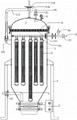
Fig. 1 is a front plan view of the novel overall structure.
Fig. 2 is a front plan view of the novel combined filter element set.
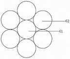
Fig. 3 is a top plan view of the novel combined filter element set.
Detailed Description
As shown in fig. 1, 2 and 3, a novel candle filter comprises a tank body 1, a water pump (not shown in the figure), a pneumatic valve 2, an upper cover 3, a solenoid valve, a clear liquid pipe 4 and a pressure gauge 5, wherein the air inlet end of the pneumatic valve 2 is connected with an exhaust pipe of an air compressor (not shown in the figure) in a workshop through a pipeline, and the novel candle filter is also provided with a combined filter element 6; the upper end and the lower end of the tank body 1 are of an open structure, the inner lower end of the tank body 1 is of a conical structure with a large upper part and a small lower part, the lower end of the tank body 1 is arranged on a support frame 7 through a screw nut, and a liquid inlet end flange of the pneumatic valve 2 is connected with a flange at the lower end of the tank body 1 through the screw nut; the outer side of the upper end of the tank body 1 is welded with a lower fixing plate 101 with a plurality of fixing holes at certain intervals, the outer side of the lower end of the upper cover is welded with an upper fixing plate 31 with a plurality of fixing holes at certain intervals, the left lower end of the upper cover 3 is hinged with the upper left part of the tank body 1, and the upper cover 3 and the upper end of the tank body 1 (a sealing rubber gasket is arranged between the upper cover 3 and the tank body 1) are sealed and installed together through the fixing holes by a plurality of screw nuts; the right side of the upper end of the upper cover 3 is welded with two connecting pipes communicated with the lower end of the upper cover, four electromagnetic valves are provided, one end of a first electromagnetic valve 81 is connected with one end of the first connecting pipe through threads, the other end of the first electromagnetic valve 81 is connected with an exhaust pipe of an air compressor through a pipeline, an air inlet end of a pressure gauge 5 (mainly used for detecting the pressure in the tank body during filtering, the pressure is over high and represents that the filtering performance of the combined filter element is poor, and vice versa, the upper part of the left end of the tank body 1 is welded with a fixed seat 102, the fixed seat 102 is provided with an ┍ -shaped connecting frame 103 through a screw nut, the right part of the upper end of the connecting frame 103 is vertically welded with a sleeve 104 with internal threads, a limiting rod 106 is screwed into the sleeve 104, the upper end of the limiting rod 106 is provided with a rotating disc 105 (clockwise rotating disc 105, the lower end of the limiting rod 106 is propped against the upper end of the upper cover 3 to play a role in strengthening the sealing capacity between the upper cover 3 and the tank body 1); a sewage pipe 8 is welded on the left side of the lower end of the tank body (communicated with the inside of the tank body), the outer side end of the sewage pipe 8 is in threaded connection with one end of a second electromagnetic valve 82, the other end of the second electromagnetic valve 82 is connected with the liquid outlet end of the water pump through a pipeline, and the liquid inlet end of the water pump is connected with a liquid discharge pipe of a sewage tank (not shown in the figure) in a production area through a pipeline; the combined filter elements 6 are provided with four groups, each group is provided with a plurality of sets of combined filter elements (two sets of five combined filter elements and the other two sets of three combined filter elements); each set of combined filter element comprises an inner tube 61, an outer tube 62 and filter cloth sleeves 63, six outer tubes 62 are provided, the surfaces of the six outer tubes 62 are annularly distributed and provided with a plurality of filter holes 621 at intervals from top to bottom, the six outer tubes 62 are annularly and vertically distributed and welded at the outer side ends of the inner tube 61, the filter cloth sleeves 63 are annularly distributed and hermetically sleeved at the outer side ends of the six outer tubes 62, the outer sides of the lower ends of the six outer tubes 62 are hermetically welded with a lower sleeve base 64 with a closed structure at the lower end, and the upper ends of the six outer tubes are hermetically welded with an upper sleeve base 65 with a closed structure at the upper end (the upper end of the inner tube is positioned outside the upper sleeve base); in each group of multi-set combined filter elements, the upper end of the inner pipe of each set of combined filter element is vertically welded at the lower end of the branch pipe 66 with a sealed structure at a certain distance from left to right, the inner pipe 61 is communicated with the branch pipe 66, and the four groups of combined filter elements 6 are respectively arranged at the upper end in the tank body 1 at a certain distance from front to back through screw nuts.
In each set of combined filter element, as shown in fig. 1, 2 and 3, the upper end of the inner tube 61 is higher than the outer tube 62, the lower end is lower than the outer tube 62, and the height of the filter cloth cover 63 is consistent with that of the outer tube 62. In each set of combined filter element, the lower end of the lower sleeve seat 64 is in a sharp cone shape; in each group of combined filter elements, the height of the middle combined filter element 6 is greater than that of other combined filter elements 6 at the two side ends, and the lower end of the middle combined filter element and the upper end of the pneumatic valve 2 are separated by a small distance (1 mm). In the four groups of combined filter elements 6, the branch pipes 66 of the four groups of combined filter elements and one end of the clear liquid pipe 4 are respectively welded together, the four branch pipes 66 and the clear liquid pipe 4 are communicated with each other, the other end of the clear liquid pipe 4 is positioned at the right outer side of the upper end of the tank body 1, the other end of the clear liquid pipe 4 is in threaded connection with one end of a three-way joint, one ends of a third electromagnetic valve 83 and a fourth electromagnetic valve 84 are respectively in pipeline connection with the other two ends of the three-way joint, the other end of the third electromagnetic valve 83 is in pipeline connection with a liquid pipe of a clear liquid tank (not shown in the figure) in a workshop, and the other end of the fourth electromagnetic valve 84 is in pipeline connection with an exhaust pipe of an air compressor.
As shown in figures 1, 2 and 3, other using methods and processes of the novel candle filter are completely consistent with those of the prior candle filter. In this is novel, during the filtration, open the power of water pump and second solenoid valve 82, third solenoid valve 83 and water pump, then, the water pump is got electric work and is filtered the sewage in the sewage jar and take out the second solenoid valve 82 pump income jar body 1 of opening through the case, the interior liquid of jar body 1 filters the interior lower extreme that gets into inner tube 61 through the filtration hole 621 of six outer tube 62 outside ends after the filter cloth cover 63 of every set of combination formula filter core filters down under the pressure effect, then in the clear liquid pipe 4 is got into through the tubulation 66 in from inner tube 61 upper end, again from clear liquid pipe 4, the third solenoid valve 83 that the case was opened flows out in the clear liquid jar in the workshop. This is novel in owing to have four groups of combination formula filter cores 6, and every group has many sets of combination formula filter cores 6, and more filter cloth cover 63 of combination formula filter core 6 has bigger filter area, has improved the filter effect who gets into jar internal 1 liquid like this, and wherein single or a plurality of combination formula filter cores 6 take place local or whole jam back, can not influence other normal filter core 6's performance, consequently can guarantee that equipment normally works. When the liquid in the sewage tank is filtered and the liquid in the tank body 1 is required to be discharged and is close to the full tank, the power supply of the second electromagnetic valve and the water pump is closed, and the power supply of the first electromagnetic valve 81 and the third electromagnetic valve 83 is opened, so that the compressed air output by the air compressor can enter the tank body 1, the compressed air acts on the liquid in the tank body and enters the outer pipe 62 from the outside of the filter cloth sleeve 63 of the multi-sleeve combined type filter element, flows into the upper end of the outer pipe 62 positioned at the upper part of the lower sleeve seat 65, flows into the inner pipe 61 from the lower end of the inner pipe 62, flows out of the upper end of the inner pipe 61 to the clear liquid pipe 4, and finally flows out of the third electromagnetic valve 83 and the clear liquid pipe 4 opened by the valve core to the clear liquid tank. In this novel middle height and jar body 1 interior lower extreme height of every group combination formula filter core 6 are close, and compressed air effect back liquid flows in from inner tube 61 lower extreme, consequently can filter whole jar internal liquid and get into in the clear solution jar (under the actual conditions, jar internal only 1 millimeter is left and right the very little liquid of height and is remained, can neglected), can guarantee as far as possible that jar internal upper and lower extreme liquid obtains filtering and discharges.
Fig. 1, 2, 3 show, this novel jar body 1 interior surplus liquid is handled the back, close first only and the third solenoid valve power and open the power of fourth solenoid valve 84 and pneumatic valve 2, then the compressed air of air compressor machine output gets into the inner tube 61 of multiunit combination formula filter core through three way connection (and gets into pneumatic valve 2, pneumatic valve 2 is opened), again from the filtration pore 621 of crossing of outer tube 62, discharge outside the filter cloth cover 63, the quick in-process that discharges of compressed air is with the adhesion filter residue and the filter cake etc. of filter core cover outside end fall, pneumatic valve 2 that opens through the case gets into the waste material jar body that is located jar body 1 lower extreme, and then accomplish whole working process.
Having shown and described the fundamental principles and essential features of the invention, and its advantages, it will be apparent to those skilled in the art that the invention is not limited to the details of the foregoing illustrative embodiments, but is capable of other specific forms without departing from the spirit or essential characteristics thereof. The present embodiments are therefore to be considered in all respects as illustrative and not restrictive, the scope of the invention being indicated by the appended claims rather than by the foregoing description, and all changes which come within the meaning and range of equivalency of the claims are therefore intended to be embraced therein.
Furthermore, it should be understood that although the present description refers to embodiments, the embodiments do not include only one independent technical solution, and such description is only for clarity, and those skilled in the art should take the description as a whole, and the technical solutions in the embodiments may be appropriately combined to form other embodiments that can be understood by those skilled in the art.
Claims (4)
1. A novel candle type filter comprises a tank body, a water pump, a pneumatic valve, an upper cover, an electromagnetic valve, a clear liquid pipe and a pressure gauge, and is characterized by also comprising a combined type filter element; the lower end of the tank body is arranged on the support frame, the liquid inlet end of the pneumatic valve is arranged with the lower end of the tank body, and the upper cover is arranged with the upper part of the tank body; the upper end of the upper cover is provided with two connecting pipes, four electromagnetic valves are arranged, one end of a first electromagnetic valve is connected with one end of the first connecting pipe, the other end of the first electromagnetic valve is connected with an exhaust pipe of the air compressor, and the pressure gauge is connected with a second connecting pipe; a sewage pipe is arranged on one side of the lower end of the tank body, the outer side end of the sewage pipe is connected with one end of a second electromagnetic valve, the other end of the second electromagnetic valve is connected with the liquid outlet end of the water pump, and the liquid inlet end of the water pump is connected with a sewage tank liquid discharge pipe in the production area; the combined filter element comprises a plurality of groups, each group comprises a plurality of combined filter elements, each combined filter element comprises an inner tube, an outer tube and a filter cloth sleeve, the outer tubes are provided with a plurality of filter holes, the surfaces of the outer tubes are provided with a plurality of filter holes, the outer tubes are annularly distributed and arranged at the outer side end of the inner tube, the filter cloth sleeves are hermetically sleeved at the outer side end of the outer tubes, the outer sides of the lower ends of the outer tubes are provided with a lower sleeve seat, and the upper ends of the outer tubes are provided with upper sleeve seats; in each group of multi-set combined filter elements, the upper end of the inner tube of each set of combined filter element is arranged at the lower end of one branch tube, the inner tube is communicated with the branch tube, and the multi-set combined filter elements are respectively arranged at the upper end in the tank body.
2. The candle filter as in claim 1, wherein in each set of combined filter elements, the upper end of the inner tube is higher than the outer tube, the lower end is lower than the outer tube, and the height of the filter cloth cover is the same as the height of the outer tube.
3. A candle filter as in claim 1, wherein the height of the middle modular filter element in each group of modular filter elements is greater than the height of the other sets of modular filter elements at the two sides.
4. The candle type filter as in claim 1, wherein in the multi-group combined filter element, the branch pipes of the multi-group combined filter element and one end of the clear liquid pipe are respectively installed together, the other end of the clear liquid pipe is located outside the upper end of the tank body, the other end of the clear liquid pipe is respectively connected with one end of a third electromagnetic valve and one end of a fourth electromagnetic valve, the other end of the third electromagnetic valve is connected with the liquid pipe of the clear liquid tank in the workshop, and the other end of the fourth electromagnetic valve is connected with the exhaust pipe of the air compressor.
Priority Applications (1)
| Application Number | Priority Date | Filing Date | Title |
|---|---|---|---|
| CN202120197704.8U CN217067912U (en) | 2021-01-25 | 2021-01-25 | Candle type filter |
Applications Claiming Priority (1)
| Application Number | Priority Date | Filing Date | Title |
|---|---|---|---|
| CN202120197704.8U CN217067912U (en) | 2021-01-25 | 2021-01-25 | Candle type filter |
Publications (1)
| Publication Number | Publication Date |
|---|---|
| CN217067912U true CN217067912U (en) | 2022-07-29 |
Family
ID=82497773
Family Applications (1)
| Application Number | Title | Priority Date | Filing Date |
|---|---|---|---|
| CN202120197704.8U Active CN217067912U (en) | 2021-01-25 | 2021-01-25 | Candle type filter |
Country Status (1)
| Country | Link |
|---|---|
| CN (1) | CN217067912U (en) |
-
2021
- 2021-01-25 CN CN202120197704.8U patent/CN217067912U/en active Active
Similar Documents
| Publication | Publication Date | Title |
|---|---|---|
| CN108671603A (en) | A kind of basket filter | |
| CN201208526Y (en) | A catalyst recovery filter | |
| CN102764527B (en) | Pore shaft water supply filter assembly and filter system | |
| CN209500969U (en) | A kind of full-automatic tubulation backwash filter | |
| CN202876493U (en) | Backwashing filter | |
| CN115105881A (en) | Candle type cake layer filter suitable for high precision and high viscosity and method thereof | |
| CN212141588U (en) | Textile processing is with fibre washing wastewater filter equipment | |
| CN104436774B (en) | Mechanical filter | |
| CN211562063U (en) | Filter barrel for backwashing filter element | |
| CN208641896U (en) | A kind of integral type is from rinsing purifier | |
| CN208948997U (en) | A kind of water resource filter of cleaning easy to disassemble | |
| CN218608335U (en) | Backwashing filter device | |
| CN207654793U (en) | A kind of cylinder filter with slag-drip opening | |
| CN214130558U (en) | Novel microporous filter | |
| CN212236763U (en) | High-efficient backwash intelligent filter | |
| CN212440281U (en) | Stainless steel tubular multilayer sintering filter screen precise filtering device capable of backwashing | |
| CN204275819U (en) | A kind of ultrafiltration apparatus for soy sauce, vinegar | |
| CN116440572A (en) | Filter device for saturator mother liquid pump and application method thereof | |
| CN211394081U (en) | Environment-friendly sewage treatment filter equipment | |
| CN221155642U (en) | Backwashing electronic grade chemical filter | |
| CN221358722U (en) | Pipeline filtering structure suitable for narrow space | |
| CN213623547U (en) | Full-automatic microporous filter | |
| CN223055422U (en) | Self-cleaning formula ceramic membrane subassembly | |
| CN223683131U (en) | Medical waste water particulate matter filtration equipment | |
| CN217188222U (en) | Filter for processing waterborne polyurethane resin |
Legal Events
| Date | Code | Title | Description |
|---|---|---|---|
| GR01 | Patent grant | ||
| GR01 | Patent grant |