Box type low-temperature instant freezing equipment
Technical Field
The utility model relates to a refrigeration technology field especially relates to a equipment is frozen in case formula low temperature is in twinkling of an eye.
Background
The scientific and technological development speed of human beings is geometric grade, the importance of advanced refrigeration technology is self-evident, modern scientific research shows that food is rapidly frozen and is easy to form a vitreous body structure, ice crystals can be formed by traditional freezing, the formation of the ice crystals is the biggest defect of traditional frozen food, whether food can be rapidly frozen directly determines whether cells in the food are frozen and broken and become meat, and the current rapid freezing method is ultra-low temperature refrigeration besides a liquid nitrogen freezing method, but the energy efficiency ratio of the ultra-low temperature refrigeration of the current refrigeration system is poor and not ideal enough.
The box-type freezing equipment is widely used in the freezing industry because the operation is simple and flexible, and small batches of the box-type freezing equipment can be frozen, the existing box-type freezing equipment generally directly puts food into the equipment for cooling when in use, and the general refrigeration mode cannot rapidly cool the food in a short time, so that the quality of the cooled food is influenced.
SUMMERY OF THE UTILITY MODEL
The utility model aims at solving the problem that the inside of the existing box-type refrigerating equipment which is used is generally directly put food into the equipment to be cooled, and the general refrigerating mode can not quickly cool the food in a short time, thereby influencing the defect of the food quality after cooling and providing the box-type low-temperature instant refrigerating equipment.
In order to achieve the above purpose, the utility model adopts the following technical scheme:
a box type low-temperature instant freezing device comprises a box body, wherein a liquid inlet pipe is installed at the top end of the box body, and a liquid outlet pipe is installed at the top end of the box body;
the top end of the box body is connected with a connecting plate, one end of the connecting plate is hinged with an installation plate, one side of the installation plate is connected with a side door, a screw disc is installed on the surface of the side door, and a hydraulic rod is installed on one side of the box body;
the refrigerator comprises a box body, a fan, an air deflector, a placing plate, a cargo box and a refrigerating calandria plate, wherein the box body is internally provided with a mounting frame, one side of the mounting frame is provided with the fan, the surface of the mounting frame is provided with the air deflector, the placing plate is internally provided with the mounting frame, the top end of the placing plate is provided with the cargo box, and the mounting frame is internally provided with the refrigerating calandria plate;
the liquid inlet pipe penetrates through the box body and is connected with a first branch pipe, and the other end of the first branch pipe is connected with a refrigeration finned tube bank;
the liquid outlet pipe penetrates through the box body and is connected with a second branch pipe, and the liquid outlet pipe penetrates through the box body and is connected with a third branch pipe;
the liquid inlet pipe penetrates through the box body and is connected with a fourth branch pipe.
As a further description of the above technical solution:
be connected between the surface of hydraulic stem and side door, and be connected between one side of side door and box, be connected for relative between one side of mounting bracket and side door.
As a further description of the above technical solution:
the spiral plate penetrates through the side door to be connected with one side of the box body, the air deflector is positioned above the cargo box, and the refrigeration calandria plate is positioned at the bottom end of the placing plate.
As a further description of the above technical solution:
the second branch pipe is connected with one side of the refrigeration finned tube bank, and the third branch pipe is connected with one side of the refrigeration tube bank plate.
As a further description of the above technical solution:
the fourth branch pipe is connected with the surface of the refrigeration calandria plate, and the refrigeration finned calandria is positioned at the upper end, the lower end and the side part of the mounting frame.
As a further description of the above technical solution:
the surface mounting of mounting bracket has heating wire and defrosting line, the heated board is installed to the both sides of side door.
To sum up, owing to adopted above-mentioned technical scheme, the beneficial effects of the utility model are that:
1. the utility model discloses in, through refrigerating system's work, can make the inside refrigeration calandria board of box and refrigeration wing calandria carry out the work of refrigerating to be convenient for refrigerate the inside food of goods incasement portion on the mounting bracket, can carry out rapid cooling to food, thereby can improve the refrigeration efficiency to food.
2. The utility model discloses in, through the work of fan, can make the wind that the fan blew off blow to the goods case through the aviation baffle, be convenient for carry out the work of cooling down to food, the cold wind that the fan blew off simultaneously is through refrigeration wing calandria and get back to the fan, can form the cold wind circulation in the inside of box, can make food freezing speed obviously improve.
3. The utility model discloses in, through the work of heating wire with change the frost line, can unfreeze the frost with side door and mounting bracket contact department, prevent that it from freezing, lead to unable opening in the side door short time, influence the quality after to the freezing of food.
Drawings
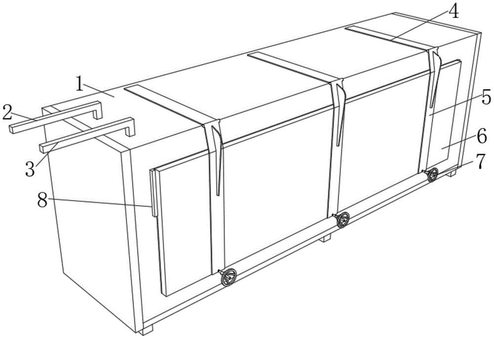
FIG. 1 is a schematic structural view of a box-type low-temperature instant freezing device of the present invention;
FIG. 2 is a schematic view of the structure of the inner part of the middle box body of the present invention;
FIG. 3 is a schematic side view of the middle box of the present invention;
FIG. 4 is a schematic view of the structure of the inner part of the middle box body of the present invention;
FIG. 5 is an enlarged schematic view of the structure at A in FIG. 2;
fig. 6 is an enlarged schematic view of B in fig. 2.
Illustration of the drawings:
1. a box body; 2. a liquid inlet pipe; 3. a liquid outlet pipe; 4. a connecting plate; 5. mounting a plate; 6. a side door; 7. a spiral disc; 8. a hydraulic lever; 9. a mounting frame; 10. a fan; 11. an air deflector; 12. placing the plate; 13. a cargo box; 14. refrigerating the tube discharging plate; 15. a first branch pipe; 16. refrigerating the finned tube bank; 17. a second branch pipe; 18. a third branch pipe; 19. a fourth branch pipe.
Detailed Description
The technical solutions in the embodiments of the present invention will be described clearly and completely with reference to the drawings in the embodiments of the present invention, and it is obvious that the described embodiments are only some embodiments of the present invention, not all embodiments. Based on the embodiments of the present invention, all other embodiments obtained by a person of ordinary skill in the art without creative efforts belong to the protection scope of the present invention.
Referring to fig. 1-6, a box type low-temperature instant freezing device comprises a box body 1, wherein a liquid inlet pipe 2 is installed at the top end of the box body 1, and a liquid outlet pipe 3 is installed at the top end of the box body 1;
the top end of the box body 1 is connected with a connecting plate 4, one end of the connecting plate 4 is hinged with a mounting plate 5, one side of the mounting plate 5 is connected with a side door 6, a screw disc 7 is mounted on the surface of the side door 6, and a hydraulic rod 8 is mounted on one side of the box body 1;
the refrigerator comprises a box body 1, a mounting frame 9, a fan 10, an air deflector 11, a placing plate 12, a cargo box 13 and a refrigerating exhaust pipe plate 14, wherein the mounting frame 9 is mounted inside the box body 1, the fan 10 is mounted on one side of the mounting frame 9, the air deflector 11 is mounted on the surface of the mounting frame 9, the placing plate 12 is mounted inside the mounting frame 9, the cargo box 13 is placed at the top end of the placing plate 12, and the refrigerating exhaust pipe plate 14 is mounted inside the mounting frame 9;
the liquid inlet pipe 2 penetrates through the box body 1 and is connected with a first branch pipe 15, and the other end of the first branch pipe 15 is connected with a refrigeration finned tube bank 16;
the liquid outlet pipe 3 penetrates through the box body 1 and is connected with a second branch pipe 17, and the liquid outlet pipe 3 penetrates through the box body 1 and is connected with a third branch pipe 18;
the liquid inlet pipe 2 penetrates through the box body 1 to be connected with a fourth branch pipe 19, the liquid inlet pipe 2 and the liquid outlet pipe 3 are connecting pipes which are conveniently connected with a refrigeration evaporator in a refrigeration system outside the box body 1 and can also be connected with a liquid storage device of refrigeration secondary refrigerant outside the box body 1, the equipment is designed into a box type low-temperature freezing box with a large side opening, the equipment is characterized in that goods are conveniently loaded and unloaded, the equipment uses the circulation of the secondary refrigerant in the refrigeration system in the box body 1 as a refrigeration source in the box, and is characterized in that enough secondary refrigerant can be pre-cooled in advance, so that the equipment reaches the pre-cooling temperature at the moment of starting operation, the cooling speed is extremely high, the equipment is designed to accelerate the cooling process according to a pressure difference type cold air circulation system, a metal refrigeration exhaust pipe plate 14 is arranged below a goods placing plate 12 of the equipment and is in contact type direct cooling with the bottom of the goods placing plate 12, the metal temperature conductivity coefficient is hundreds times of water and air, the process is additionally provided with a layer of film covered on the goods in the tray, a layer of stainless steel wire balls stacked on the film, and a metal plate covered on the steel wire balls, so that the original air heat conduction of the upper part of the goods is changed into metal heat conduction, and the temperature coefficient is greatly increased.
Further, be connected between the surface of hydraulic stem 8 and side door 6, and be connected between one side of side door 6 and box 1, be connected relatively between one side of mounting bracket 9 and side door 6, box 1 is opened through side door 6 of both sides, and its upper and lower extreme all is fixed, and the heating wire is installed in the contact department of mounting bracket 9 and side door 6 with the line of changing frost, and it prevents that frozen phenomenon from appearing in its contact department.
Further, the spiral shell dish 7 passes and is connected between one side of side door 6 and box 1, aviation baffle 11 is located the top of cargo box 13, refrigeration calandria board 14 is located the bottom of placing board 12, spiral shell dish 7 is the one side of being convenient for install side door 6 at box 1, when needs are opened, can with spiral shell dish 7 from box 1 inside roll-out can, aviation baffle 11 is the wind direction cargo box 13 of being convenient for blow out fan 10, be convenient for carry out rapid cooling and freezing to the inside food of cargo box 13.
Furthermore, the second branch pipe 17 is connected with one side of the refrigeration finned tube bank 16, the third branch pipe 18 is connected with one side of the refrigeration tube bank plate 14, the first branch pipe 15 and the fourth branch pipe 19 are connected with the liquid inlet pipe 2, and the third branch pipe 18 and the second branch pipe 17 are connected with the liquid outlet pipe 3, so that the refrigeration tube bank plate 14 and the refrigeration finned tube bank 16 in the box body 1 can work conveniently.
Furthermore, the fourth branch pipe 19 is connected to the surface of the cooling exhaust pipe 14, the cooling fin pipes 16 are located at the upper, lower, and side portions of the mounting frame 9, and the fan 10 blows cold air into the box 1, and the cold air can pass through the cooling fin pipes 16 at the upper, lower, and side portions of the mounting frame 9 and return to the fan 10.
Further, the surface mounting of mounting bracket 9 has the heating wire and changes the frost line, and the heated board is installed to the both sides of side door 6, and the heated board of 6 both sides of side door is convenient for keep warm to the inside of box 1, and the heating wire with change the frost line prevent that the phenomenon of freezing from appearing in mounting bracket 9 and the contact department of side door 6, lead to unable normal opening in the side door 6 short time.
The working principle is as follows: when in use, firstly, the screw disk 7 is rotated out of the box body 1, the side door 6 is opened, food and the like are put into the goods box 13, the side door 6 is closed, the screw disk 7 limits the position of the side door, the liquid inlet pipe 2 and the liquid outlet pipe 3 are connected with a refrigerating system outside the box body 1, the calandria refrigerating calandria plate 14 and the refrigerating fin calandria 16 can work through the work of the refrigerating system to ensure that the calandria refrigerating calandria plate can reach the specified refrigerating capacity, the liquid inlet pipe 2 and the liquid outlet pipe 3 can also be connected with a secondary refrigerant reservoir outside the box body 1, when the refrigeration is needed, the liquid supply pump works, the refrigerating calandria plate 14 and the refrigerating fin calandria 16 start to refrigerate, the air can be blown to the box body 1 through the work of the fan 10 inside the box body 1, the air can pass through the refrigerating fin 16 and return to the fan 10 to form a cold air circulation, the screw disk 7 is rotated out after the time is set according to the refrigeration, and the side door 6 is opened, the frozen food in the cargo box 13 can be taken out, and when the side door 6 is frozen, the defrosting and thawing can be performed on the contact position of the side door 6 and the mounting rack 9 through the work of the electric heating wire and the defrosting line.
The above, only be the concrete implementation of the preferred embodiment of the present invention, but the protection scope of the present invention is not limited thereto, and any person skilled in the art is in the technical scope of the present invention, according to the technical solution of the present invention and the utility model, the concept of which is equivalent to replace or change, should be covered within the protection scope of the present invention.