CN217052801U - A raw materials edulcoration device for textile production - Google Patents
A raw materials edulcoration device for textile production Download PDFInfo
- Publication number
- CN217052801U CN217052801U CN202220824514.9U CN202220824514U CN217052801U CN 217052801 U CN217052801 U CN 217052801U CN 202220824514 U CN202220824514 U CN 202220824514U CN 217052801 U CN217052801 U CN 217052801U
- Authority
- CN
- China
- Prior art keywords
- blocks
- rotating shaft
- grooves
- arc
- textile production
- Prior art date
- Legal status (The legal status is an assumption and is not a legal conclusion. Google has not performed a legal analysis and makes no representation as to the accuracy of the status listed.)
- Expired - Fee Related
Links
- 239000002994 raw material Substances 0.000 title claims abstract description 67
- 238000004519 manufacturing process Methods 0.000 title claims abstract description 31
- 239000004753 textile Substances 0.000 title claims abstract description 29
- 239000012535 impurity Substances 0.000 claims description 21
- 238000007599 discharging Methods 0.000 claims description 16
- 238000004804 winding Methods 0.000 claims description 16
- 239000000463 material Substances 0.000 claims description 9
- 230000037431 insertion Effects 0.000 claims 5
- 238000003780 insertion Methods 0.000 claims 5
- 230000001360 synchronised effect Effects 0.000 claims 1
- 238000007664 blowing Methods 0.000 abstract description 8
- 230000006978 adaptation Effects 0.000 abstract description 6
- 230000000694 effects Effects 0.000 description 11
- 238000000034 method Methods 0.000 description 8
- 239000004744 fabric Substances 0.000 description 3
- 230000009286 beneficial effect Effects 0.000 description 2
- 238000010586 diagram Methods 0.000 description 2
- 238000005457 optimization Methods 0.000 description 2
- 238000005096 rolling process Methods 0.000 description 2
- 239000010425 asbestos Substances 0.000 description 1
- 230000002457 bidirectional effect Effects 0.000 description 1
- 238000004140 cleaning Methods 0.000 description 1
- 230000003749 cleanliness Effects 0.000 description 1
- 230000003111 delayed effect Effects 0.000 description 1
- 239000000428 dust Substances 0.000 description 1
- 239000000835 fiber Substances 0.000 description 1
- 238000009434 installation Methods 0.000 description 1
- 238000002955 isolation Methods 0.000 description 1
- 229910052895 riebeckite Inorganic materials 0.000 description 1
- 239000011435 rock Substances 0.000 description 1
- 238000003860 storage Methods 0.000 description 1
- 238000009941 weaving Methods 0.000 description 1
Images



Landscapes
- Treatment Of Fiber Materials (AREA)
Abstract
The utility model provides a raw materials edulcoration device for textile production. A raw materials edulcoration device for textile production includes the base, the top fixed mounting of base has the frame, fixed mounting has the diaphragm on the top inner wall of frame, the bottom fixed mounting of diaphragm has two box bodys, two the opening is all established to one side of box body, the top fixed mounting of base has two riser one, two the arc groove has all been seted up at the top of riser one, two be equipped with same blowing roller in the arc groove, two the top of riser one articulates there are two arc cards, two the arc card respectively with the both ends looks adaptation of blowing roller. The utility model provides a raw materials edulcoration device for textile production has that the clearance is effectual, and the clearance work can continuously go on, and can accelerate the raw materials to change, improves work efficiency's advantage.
Description
Technical Field
The utility model relates to the technical field of weaving, especially, relate to a raw materials edulcoration device for textile production.
Background
The present invention relates to a method for producing fabric, and is characterized by that in the course of production and processing of fabric, the most common raw material is fibre strip or braided wire, and both are basically necessary raw materials for making fabric into finished product.
However, in the production process using these raw materials, in order to make the produced textile clean and tidy, the raw materials are generally subjected to impurity removal and ash removal before production, in order to ensure the cleanliness of raw materials, the prior art provides a raw material impurity removal device for textile production, which relates to the technical field of textile production and comprises a fixing frame, an impurity removing box is fixedly arranged at one side of the top end of the fixing frame, a dust collector is fixedly arranged at one side of the top end of the impurity removing box, one side of the outer surface of the impurity removing box is hinged with a box door, one side of the top end of the fixing frame close to the impurity removing box is fixedly provided with a raw material wheel, the other side of the top end of the fixed frame, which is close to the impurity removing box, is fixedly provided with a motor, one side of the top end of the fixed frame, which is close to the motor, is fixedly provided with a supporting frame, the inner wall one side of support frame is provided with the receipts material wheel, first through-hole has been seted up to the corresponding one side of receiving the material wheel of inner wall of edulcoration case. Though this utility model a raw materials edulcoration device for textile production, can make the integrated device process out cleaner textile raw materials, improve user of service's work efficiency, bring better use prospect
However, when the novel electric rolling machine is used, a certain gap is formed between the bristles in the first brush and the second brush, so that the raw materials are easily clamped in the first brush and the second brush and cannot be cleaned, the whole machine is stopped when the two brushes are abraded greatly and need to be replaced, long time is delayed, the working efficiency is reduced, in addition, the fixing modes of the raw material wheel and the material receiving wheel on the novel electric rolling machine are more traditional, after one batch of raw materials are rolled, the next batch of raw materials need to be replaced for a long time, and the working efficiency is further reduced.
Therefore, it is necessary to provide a new raw material impurity removal device for textile production to solve the above technical problems.
SUMMERY OF THE UTILITY MODEL
The utility model provides a technical problem provide a clearance is effectual, and the cleaning work can continuously go on, and can accelerate the raw materials change, improves work efficiency's a raw materials edulcoration device for textile production.
In order to solve the technical problem, the utility model provides a raw materials edulcoration device for textile production includes: the automatic discharging device comprises a base, wherein a frame is fixedly arranged at the top of the base, a transverse plate is fixedly arranged on the inner wall of the top of the frame, two box bodies are fixedly arranged at the bottom of the transverse plate, one side of each of the two box bodies is provided with an opening, a first vertical plate is fixedly arranged at the top of the base, arc grooves are formed in the tops of the first vertical plates, the same discharging roller is arranged in the two arc grooves, two arc clamping pieces are hinged to the tops of the first vertical plates and are respectively matched with the two ends of the discharging roller, one side of each arc clamping piece is fixedly connected with the first vertical plate through a countersunk bolt, a second vertical plate is fixedly arranged at the top of the base, a first rotating shaft and a second rotating shaft are respectively rotatably arranged on the second vertical plates, grooves are formed in the first rotating shaft and the second rotating shaft, and one side, close to each other, of the two grooves is provided with an opening, two all be equipped with the connecting block in the recess, two one side fixed mounting that the connecting block is close to each other has same material roller, two all rotate in the box body and install two-way screw rod, two equal threaded mounting has the fly leaf, corresponding two on the two-way screw rod the equal fixed mounting in one side that the fly leaf is close to each other has the linkage board, corresponding two one side that the linkage board is close to each other all is equipped with the sponge piece.
Preferably, four slots are formed in the linkage plate, inserting blocks are arranged in the four slots, the slots are matched with the inserting blocks, and the inserting blocks are fixedly connected with the corresponding sponge blocks.
Preferably, four equal fixed mounting has the one end of tight spring on the fly leaf, four the other end of tight spring all with correspond linkage board fixed connection, just slidable mounting has two slide bars on the fly leaf, two the one end of slide bar all with linkage board fixed connection.
Preferably, keep away from pivot two rotate on the riser two and install the connecting rod, and keep away from pivot two fixed mounting has the motor on the riser two, the output shaft of motor with the one end fixed connection of connecting rod, the connecting rod with it is equipped with the synchronizing wheel, two all to fix the cover on the pivot one the cover is equipped with same hold-in range, keeps away from pivot one fixed mounting has the cylinder on the riser two, fixed mounting has the arc clamp plate on the output shaft of cylinder, the inner wall of arc clamp plate with pivot two phase contact.
Preferably, two circular slots have been all seted up on the connecting block, two all be equipped with the disk in the circular slot, the disk with circular slot looks adaptation, equal threaded mounting has the bolt on pivot one and the pivot two, two the one end of bolt all with correspond disk fixed connection.
Preferably, four the constant head tank has all been seted up on the inserted block, four the activity groove has all been seted up on the inner wall of one side of slot, four equal slidable mounting has the locating piece in the activity inslot, four one side of locating piece all extends to corresponding in the constant head tank, the locating piece with constant head tank looks adaptation, four equal threaded mounting has the screw rod, four on the linkage board the one end of screw rod all extends to corresponding in the activity inslot and with corresponding the locating piece rotates to be connected.
Preferably, balls are inlaid on the inner wall of the arc groove and the inner wall of the arc clamping piece, and the balls are in contact with the end portion of the discharging roller.
Compared with the prior art, the utility model provides a raw materials edulcoration device for textile production has following beneficial effect:
the utility model provides a raw materials edulcoration device for textile production, through two arc cards that set up, and the grafting of recess and connecting block, alright convenient and fast change the blowing roller with around the material roller, work efficiency is improved, and, sponge piece can and the raw materials between tightly contact comprehensive again, make the clearance effect obtain the optimization adjustment, the clearance effect promotes huge, furthermore, in-process through two sets of sponge pieces, can be continuously carrying out the raw materials edulcoration, changing the sponge piece in turn, thereby make the edulcoration process not interrupt, work efficiency is further improved.
Drawings
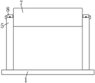
Fig. 1 is a schematic structural diagram of a preferred embodiment of a raw material impurity removal device for textile production according to the present invention;
FIG. 2 is a schematic side view of the first riser shown in FIG. 1;
FIG. 3 is a schematic side view of two risers II shown in FIG. 1;
FIG. 4 is a schematic view of the top-down connection structure of the first rotating shaft, the winding roller and the second rotating shaft of the present invention;
FIG. 5 is a schematic view of the front view structure of the box body of the present invention;
FIG. 6 is an enlarged schematic view of the portion A shown in FIG. 5;
fig. 7 is a schematic side view of the middle box body of the present invention.
The reference numbers in the figures: 1. a base; 2. a frame; 3. a transverse plate; 4. a case body; 5. a first vertical plate; 6. an arc groove; 7. a discharge roller; 8. an arc-shaped card; 9. a second vertical plate; 10. a first rotating shaft; 11. a second rotating shaft; 12. a groove; 13. connecting blocks; 14. a winding roller; 15. a circular groove; 16. a bolt; 17. a bidirectional screw; 18. a movable plate; 19. a linkage plate; 20. a sponge block; 21. inserting slots; 22. inserting a block; 23. and (5) tightening the spring.
Detailed Description
The present invention will be further described with reference to the accompanying drawings and embodiments.
Please refer to fig. 1, fig. 2, fig. 3, fig. 4, fig. 5, fig. 6 and fig. 7 in combination, wherein fig. 1 is a schematic structural diagram of a raw material impurity removing device for textile production according to a preferred embodiment of the present invention; FIG. 2 is a side view of the first riser shown in FIG. 1; FIG. 3 is a side view of the two risers shown in FIG. 1; fig. 4 is a schematic view of the overlooking connection structure of the first rotating shaft, the winding roller and the second rotating shaft of the present invention; FIG. 5 is a schematic view of the front view structure of the box body of the present invention; FIG. 6 is an enlarged schematic view of portion A of FIG. 5; fig. 7 is a schematic side view of the box body of the present invention. A raw materials edulcoration device for textile production includes: the base 1 is fixedly provided with a frame 2 at the top of the base 1, the frame 2 is designed in an inverted U shape so as to form a semi-enclosed posture and enclose each component therein so as to form a certain isolation protection effect, the inner wall of the top of the frame 2 is fixedly provided with a transverse plate 3, the bottom of the transverse plate 3 is fixedly provided with two box bodies 4, one side of each of the two box bodies 4 is provided with an opening, the top of the base 1 is fixedly provided with two first vertical plates 5, the tops of the two first vertical plates 5 are respectively provided with an arc groove 6, the two arc grooves 6 are internally provided with the same discharging roller 7, the tops of the two first vertical plates 5 are hinged with two arc clamping pieces 8, the two arc clamping pieces 8 are respectively matched with two ends of the discharging roller 7, the arc clamping pieces 8 can be in space fit with the arc grooves 6, the end parts of the discharging roller 7 are reliably placed therein so as to ensure the rotation performance of the discharging roller 7, one side of the arc-shaped clamping piece 8 is fixedly connected with a first vertical plate 5 through a countersunk head bolt, two second vertical plates 9 are fixedly installed at the top of the base 1, a first rotating shaft 10 and a second rotating shaft 11 are respectively installed on the two second vertical plates 9 in a rotating manner, grooves 12 are respectively formed in the first rotating shaft 10 and the second rotating shaft 11, one sides, close to each other, of the two grooves 12 are respectively provided with an opening, connecting blocks 13 are respectively arranged in the two grooves 12, the connecting blocks 13 are in a matching relationship with the grooves 12, the connecting blocks 13 are in tight contact with the side walls of the grooves 12, so that the winding roller 14 is prevented from loosening, the same winding roller 14 is fixedly installed at one side, two-way screw rods 17 are respectively installed in the two box bodies 4 in a rotating manner, the bottom ends of the two-way screw rods 17 extend to the lower parts of the box bodies 4 and are fixedly provided with rotating wheels, so that people can conveniently rotate, movable plates 18 are installed on the two-way screw rods 17 in a threaded manner, two limiting rods are fixed in the box body 4, penetrate through the two movable plates 18 and are in sliding connection with the two movable plates 18, the limiting rods can provide sliding limitation for the limiting rods, the limiting rods can only perform vertical linear lifting, linkage plates 19 are fixedly mounted on the sides, close to each other, of the two corresponding movable plates 18, and sponge blocks 20 are arranged on the sides, close to each other, of the two corresponding linkage plates 19.
All seted up slot 21 on four linkage boards 19, all be equipped with inserted block 22 in four slots 21, slot 21 and inserted block 22 looks adaptation, the two is pegged graft closely for sponge piece 20 is by the reliable stability of fixed, can not rock, and four inserted blocks 22 all with the sponge piece 20 fixed connection that corresponds.
The four movable plates 18 are all fixedly provided with one ends of the tightening springs 23, the other ends of the tightening springs 23 are all fixedly connected with the corresponding linkage plates 19, the tightening springs 23 can provide elastic jacking force for the sponge blocks 20, so that the two corresponding sponge blocks 20 are in tighter contact, impurities can be better stripped from the raw materials, the movable plates 18 are slidably provided with two sliding rods, and one ends of the two sliding rods are all fixedly connected with the linkage plates 19.
Keep away from two risers 9 of pivot two 11 and go up the rotation and install the connecting rod, and keep away from two risers 9 of pivot two 11 and go up fixed mounting and have the motor, the output shaft of motor and the one end fixed connection of connecting rod, it is equipped with the synchronizing wheel all to fix the cover on connecting rod and the pivot 10, the cover is equipped with same hold-in range on two synchronizing wheels, keep away from two risers 9 of pivot one 10 and go up fixed mounting and have the cylinder, fixed mounting has the arc clamp plate on the output shaft of cylinder, the inner wall of arc clamp plate contacts with two pivots 11, the arc clamp plate is made for the asbestos material, and have great frictional force between two pivots 11, thereby when the change is around material roller 14, prevent that two pivots 11 from taking place natural rotation.
All seted up the circular slot 15 on two connecting blocks 13, all be equipped with the disk in two circular slots 15, disk and circular slot 15 looks adaptation, equal threaded mounting has bolt 16 on pivot one 10 and the two 11 pivots, two bolt 16's one end all with the disk fixed connection that corresponds, all set up threaded hole on pivot one 10 and the two 11 pivots, two bolt 16 all run through the screw hole that corresponds and close soon with the inner wall of the screw hole that corresponds and be connected, and the diameter of disk is less than the screw hole diameter, thereby guarantee when rotating bolt 16, can make the disk enter into threaded hole, in order to guarantee the normal dismouting of connecting block 13.
The constant head tank has all been seted up on four inserted blocks 22, the activity groove has all been seted up on one side inner wall of four slots 21, the equal slidable mounting of four activity inslot has the locating piece, one side of four locating pieces all extends to in the constant head tank that corresponds, locating piece and positioning groove looks adaptation, the two is pegged graft closely, make the tight fixing of locating piece in the constant head tank, thereby guarantee sponge piece 20's installation stability, equal threaded mounting has the screw rod on four linkage boards 19, the one end of four screw rods all extends to the activity inslot that corresponds and rotates with the locating piece that corresponds and be connected.
All inlayed the ball on the inner wall of arc groove 6 and arc card 8's the inner wall, the ball contacts with the tip of blowing roller 7, and the ball enables the smooth emergence of blowing roller 7 and rotates to can be smooth release the raw materials.
The utility model provides a theory of operation that is used for textile production's raw materials edulcoration device as follows:
in the device, the discharging roller 7 is wound with the linear raw materials to be purified, the winding mode of the raw materials can be a designated storage mode, then more discharging rollers 7 are arranged, the linear raw materials are wound on the discharging rollers, and in addition, the number of the winding rollers 14 is also more, and the raw materials are supplied for winding;
when the raw materials are subjected to impurity removal, firstly two arc-shaped clamping pieces 8 are opened, then the discharging roller 7 wound with the raw materials is placed in two arc grooves 6, then the arc-shaped clamping pieces 8 are clamped and fixed, at the moment, the discharging roller 7 is in close contact with balls, so that the discharging roller can smoothly roll, then, one end of the raw materials passes through four sponge blocks 20 and is pulled to the winding roller 14 for fixing, then, one of the two-way screw rods 17 is rotated, so that the two corresponding movable plates 18 are close to each other, the two corresponding linkage plates 19 are also close to each other, after the two corresponding sponge blocks 20 are contacted, the raw materials are positioned between the two sponge blocks 20 and are contacted with the two sponge blocks 20, then, the two-way screw rods 17 are continuously rotated, so that the two corresponding tightening springs 23 start to be stressed and compressed, and the two corresponding sponge blocks 20 are tightly contacted with the raw materials, then stopping rotating, starting a motor, driving an output shaft of the motor to rotate a winding roller 14, then starting to wind the raw materials, releasing the raw materials by a discharging roller 7 along with the winding of the raw materials, and horizontally moving the raw materials between two sponge blocks 20 in contact in the process of releasing and winding at the same time, so that impurities attached to the raw materials can be removed by the sponge blocks 20;
when two sponge blocks 20 which are in contact are worn and need to be replaced in the impurity removing process, rotating the other two-way screw 17 to enable the other two sponge blocks 20 to be close to each other and finally to be in contact with the raw material in the same form, then reversing the previous two-way screw 17 to enable the two worn sponge blocks 20 to be far away from each other and finally to be separated from the raw material, then rotating the corresponding two screws to enable the corresponding two positioning blocks to be moved out of the corresponding positioning grooves, thereby enabling the corresponding two inserting blocks 22 to be out of limitation, then taking down the worn sponge blocks 20, replacing with new ones, reversing the corresponding two screws, inserting the positioning blocks into the inserting blocks 22 on the new sponge blocks 20, thereby completing replacement, and adjusting the two replaced sponge blocks 20 to be in contact with the raw material in the same way until the other two sponge blocks 20 need to be replaced, then the worn sponge block 20 is replaced;
after putting up the raw materials on blowing roller 7, promptly a batch of raw materials edulcoration finishes the back promptly, open two arc cards 8, it remains the blowing roller 7 of edulcoration raw materials and fixes to change the winding again, subsequently, the output shaft that starts the cylinder earlier stretches out, support two 11 of pivot with the arc clamp plate, make two 11 of pivot compress tightly the restriction, make it can not free rotation, then, rotate two bolts 16, take two circles out the circular slot 15 that corresponds, then will twine the winding roller 14 taking off of the raw materials that the edulcoration finishes, changing new winding roller 14, the output shaft withdrawal of starting the cylinder afterwards, alright continue the edulcoration work of next batch of raw materials.
Compared with the prior art, the utility model provides a raw materials edulcoration device for textile production has following beneficial effect:
the utility model provides a raw materials edulcoration device for textile production, two arc cards 8 through setting up, and the grafting of recess 12 and connecting block 13, alright convenient and fast change blowing roller 7 and around material roller 14, work efficiency is improved, and, sponge piece 20 can and the raw materials between tightly be in contact comprehensive again, make the clearance effect obtain the optimization adjustment, the clearance effect promotes huge, furthermore, through two sets of sponge piece 20's alternate use, can be continuously carrying out the in-process of raw materials edulcoration, alternate changing sponge piece 20, thereby make the edulcoration process not interrupt, and further improve work efficiency.
The above only is the embodiment of the present invention, not limiting the scope of the present invention, all the equivalent structures or equivalent processes of the present invention are used in the specification and the attached drawings, or directly or indirectly applied to other related technical fields, and the same principle is included in the protection scope of the present invention.
Claims (7)
1. A raw material impurity removal device for textile production comprises a base and is characterized in that a frame is fixedly mounted at the top of the base, a transverse plate is fixedly mounted on the inner wall of the top of the frame, two box bodies are fixedly mounted at the bottom of the transverse plate, an opening is formed in one side of each of the two box bodies, two first vertical plates are fixedly mounted at the top of the base, arc grooves are formed in the tops of the two first vertical plates, the same emptying roller is arranged in the two arc grooves, two arc clamping pieces are hinged to the tops of the two first vertical plates, the two arc clamping pieces are respectively matched with two ends of the emptying roller, one sides of the arc clamping pieces are fixedly connected with the first vertical plates through countersunk bolts, two second vertical plates are fixedly mounted at the top of the base, and a first rotating shaft and a second rotating shaft are respectively rotatably mounted on the two vertical plates, the first rotating shaft and the second rotating shaft are provided with grooves, two grooves are formed in one side, close to each other, of each groove and are formed into an opening, two connecting blocks are arranged in the grooves, two connecting blocks are fixedly mounted on one side, close to each other, of each connecting block, the same material winding roller is arranged on the two sides of each connecting block, two-way screw rods are installed in the box body in a rotating mode, the movable plates are installed on the two-way screw rods in a threaded mode, the movable plates are corresponding to each other, a linkage plate is fixedly mounted on one side, close to each other, of each movable plate, and a sponge block is arranged on one side, close to each other, of each linkage plate.
2. The raw material impurity removing device for textile production according to claim 1, wherein four of the linkage plates are provided with slots, four of the slots are provided with insertion blocks, the slots are matched with the insertion blocks, and the four insertion blocks are fixedly connected with the corresponding sponge blocks.
3. The raw material impurity removing device for textile production according to claim 1, wherein one end of a tightening spring is fixedly mounted on each of the four movable plates, the other end of each of the four tightening springs is fixedly connected with the corresponding linkage plate, two sliding rods are slidably mounted on the movable plates, and one ends of the two sliding rods are fixedly connected with the linkage plate.
4. The raw material impurity removing device for textile production according to claim 1, wherein a connecting rod is rotatably mounted on the second vertical plate far away from the second rotating shaft, a motor is fixedly mounted on the second vertical plate far away from the second rotating shaft, an output shaft of the motor is fixedly connected with one end of the connecting rod, synchronizing wheels are fixedly sleeved on the connecting rod and the first rotating shaft, the two synchronizing wheels are sleeved with the same synchronous belt, an air cylinder is fixedly mounted on the second vertical plate far away from the first rotating shaft, an arc-shaped pressing plate is fixedly mounted on the output shaft of the air cylinder, and the inner wall of the arc-shaped pressing plate is in contact with the second rotating shaft.
5. The raw material impurity removing device for textile production according to claim 1, wherein circular grooves are formed in the two connecting blocks, circular blocks are arranged in the two circular grooves, the circular blocks are matched with the circular grooves, bolts are mounted on the first rotating shaft and the second rotating shaft in a threaded mode, and one ends of the two bolts are fixedly connected with the corresponding circular blocks.
6. The raw material impurity removing device for textile production as claimed in claim 2, wherein each of the four insertion blocks is provided with a positioning groove, each of the four insertion grooves is provided with a movable groove on an inner wall of one side thereof, each of the four movable grooves is slidably provided with a positioning block, one side of each of the four positioning blocks extends into the corresponding positioning groove, the positioning blocks are adapted to the positioning grooves, each of the four linkage plates is provided with a screw, and one end of each of the four screws extends into the corresponding movable groove and is rotatably connected with the corresponding positioning block.
7. A raw material impurity removal device for textile production according to claim 1, wherein balls are inlaid on both the inner wall of the arc groove and the inner wall of the arc clamping piece, and the balls are in contact with the end portion of the discharging roller.
Priority Applications (1)
| Application Number | Priority Date | Filing Date | Title |
|---|---|---|---|
| CN202220824514.9U CN217052801U (en) | 2022-04-11 | 2022-04-11 | A raw materials edulcoration device for textile production |
Applications Claiming Priority (1)
| Application Number | Priority Date | Filing Date | Title |
|---|---|---|---|
| CN202220824514.9U CN217052801U (en) | 2022-04-11 | 2022-04-11 | A raw materials edulcoration device for textile production |
Publications (1)
| Publication Number | Publication Date |
|---|---|
| CN217052801U true CN217052801U (en) | 2022-07-26 |
Family
ID=82470956
Family Applications (1)
| Application Number | Title | Priority Date | Filing Date |
|---|---|---|---|
| CN202220824514.9U Expired - Fee Related CN217052801U (en) | 2022-04-11 | 2022-04-11 | A raw materials edulcoration device for textile production |
Country Status (1)
| Country | Link |
|---|---|
| CN (1) | CN217052801U (en) |
-
2022
- 2022-04-11 CN CN202220824514.9U patent/CN217052801U/en not_active Expired - Fee Related
Similar Documents
| Publication | Publication Date | Title |
|---|---|---|
| CN217437297U (en) | Winding mechanism for warp knitted fabric | |
| CN215625586U (en) | Winding mechanism for textile machinery | |
| CN117626626B (en) | Cashmere textile fabric surface impurity-removing device | |
| CN112660891A (en) | Batting clearing device for textile machinery with direction function | |
| CN219157253U (en) | Surface fabric dust collector is used in surface fabric processing | |
| CN112499326A (en) | Plush scrap removing winding machine for plush toy cloth processing | |
| CN221587431U (en) | Device convenient for winding cotton fabric | |
| CN221478972U (en) | Textile fabric ironing and winding device | |
| CN216864460U (en) | Rapier weaving machine collection device for bath towel | |
| CN212245676U (en) | A cotton roll compaction device for a spinning roll forming machine | |
| CN109267281B (en) | A textile fabric leveling device | |
| CN222250792U (en) | Automatic leather cleaning machine of leather production line | |
| CN223251244U (en) | Automatic polishing device with cleaning function for galvanized wire | |
| CN221988785U (en) | Cloth cover tension adjusting device of loom | |
| CN222043613U (en) | Ironing device for fabric processing | |
| CN219315332U (en) | Winding device for functional spandex fiber | |
| CN220299844U (en) | A fabric weaving textile roller | |
| CN112301715A (en) | Two-sided cleaning device of textile fabric | |
| CN221644008U (en) | Quick winding device for producing polyester grey cloth | |
| CN223445816U (en) | A cloth brushing device with a cleaning mechanism | |
| CN223043355U (en) | A round aluminum wire drawing and fixing device | |
| CN221234918U (en) | A textile cloth winding device | |
| CN222907072U (en) | Nonwoven fabric feeding device | |
| CN221459333U (en) | Coiling mechanism is used in production of sandwich screen cloth | |
| CN218812354U (en) | Spinning unit of yarn |
Legal Events
| Date | Code | Title | Description |
|---|---|---|---|
| GR01 | Patent grant | ||
| GR01 | Patent grant | ||
| CF01 | Termination of patent right due to non-payment of annual fee |
Granted publication date: 20220726 |
|
| CF01 | Termination of patent right due to non-payment of annual fee |