CN217037849U - Land reclamation is with leveling device - Google Patents
Land reclamation is with leveling device Download PDFInfo
- Publication number
- CN217037849U CN217037849U CN202220820635.6U CN202220820635U CN217037849U CN 217037849 U CN217037849 U CN 217037849U CN 202220820635 U CN202220820635 U CN 202220820635U CN 217037849 U CN217037849 U CN 217037849U
- Authority
- CN
- China
- Prior art keywords
- fixedly connected
- frame
- type
- roller
- plate
- Prior art date
- Legal status (The legal status is an assumption and is not a legal conclusion. Google has not performed a legal analysis and makes no representation as to the accuracy of the status listed.)
- Expired - Fee Related
Links
- 238000004140 cleaning Methods 0.000 claims abstract description 31
- 239000002689 soil Substances 0.000 claims abstract description 15
- 238000005067 remediation Methods 0.000 claims abstract description 9
- 230000005540 biological transmission Effects 0.000 claims abstract description 8
- 238000009434 installation Methods 0.000 claims description 11
- 238000005096 rolling process Methods 0.000 description 19
- 238000007596 consolidation process Methods 0.000 description 4
- 230000009286 beneficial effect Effects 0.000 description 2
- 238000010586 diagram Methods 0.000 description 2
- 244000025254 Cannabis sativa Species 0.000 description 1
- 238000010276 construction Methods 0.000 description 1
- 230000007812 deficiency Effects 0.000 description 1
- 230000000694 effects Effects 0.000 description 1
- 238000005516 engineering process Methods 0.000 description 1
- 239000004459 forage Substances 0.000 description 1
- 238000000034 method Methods 0.000 description 1
- 230000004048 modification Effects 0.000 description 1
- 238000012986 modification Methods 0.000 description 1
- 239000011435 rock Substances 0.000 description 1
Images


Landscapes
- Soil Working Implements (AREA)
Abstract
本实用新型属于土地工程技术领域,尤其为一种土地整治用平整装置,包括T型支撑板,所述T型支撑板的顶部固定连接有固定板,所述固定板的一侧安装有一号伺服电机,所述一号伺服电机的输出端固定连接有螺纹杆,所述螺纹杆的另一端通过轴承连接有L型固定架。本实用新型通过一号伺服电机、螺纹杆、移动套和连接板的设计下,是为了配合以二号伺服电机、一号皮带轮、传动带、二号皮带轮、转动杆、清洁辊和刮板组成的清洁机构,可以在L型固定架的上方进行水平移动,然后碾压辊在气缸的调节配合下,可以调节碾压辊与清洁辊之间的高度位置,这样有助于配合清洁机构对碾压辊表面的泥土进行自动化清洁,从而提高该碾压辊对泥土平整的高效性。
The utility model belongs to the technical field of land engineering, in particular to a leveling device for land remediation, comprising a T-shaped support plate, a fixed plate is fixedly connected to the top of the T-shaped support plate, and a No. 1 servo is installed on one side of the fixed plate The motor, the output end of the No. 1 servo motor is fixedly connected with a threaded rod, and the other end of the threaded rod is connected with an L-shaped fixing frame through a bearing. The utility model is designed by the No. 1 servo motor, the threaded rod, the moving sleeve and the connecting plate, and is composed of the No. 2 servo motor, the No. 1 pulley, the transmission belt, the No. 2 pulley, the rotating rod, the cleaning roller and the scraper. The cleaning mechanism can move horizontally above the L-shaped fixed frame, and then the roller can adjust the height between the roller and the cleaning roller under the adjustment of the air cylinder, which is helpful for the cleaning mechanism. The soil on the surface of the roller is cleaned automatically, thereby increasing the efficiency of the roller for soil leveling.
Description
技术领域technical field
本实用新型涉及土地工程技术领域,具体为一种土地整治用平整装置。The utility model relates to the technical field of land engineering, in particular to a leveling device for land consolidation.
背景技术Background technique
目前,在土地工程建设中,对于土地场地清理与土地平整的主要是清除土壤表层妨碍机械作业、影响牧草生长的岩石、树桩等,一般清理深度为三十五厘米左右,而在平整土地过程中,最后一般都需要对土地进行压平平整,所以经常用到土地平整装置。At present, in the construction of land engineering, the main tasks for land site clearing and land leveling are to remove the rocks and tree stumps that hinder mechanical operations and affect the growth of forage grass on the soil surface. Generally, the depth of clearing is about 35 cm. In the end, the land generally needs to be flattened and leveled, so the land leveling device is often used.
现有的土地整治用平整装置,一般是以碾压辊在土地表面移动,并依靠碾压辊自身的重量,对土地表面进行碾压,从而达到土地表面整平的目的,但是该碾压辊在对土地碾压的同时,碾压辊的表面也会粘附大量的泥土,这样就严重影响该碾压辊对土地碾压的平整性,从而就降低了该装置的工作效率。The existing leveling device for land remediation generally uses a rolling roller to move on the land surface, and relies on the weight of the rolling roller to roll the land surface, so as to achieve the purpose of leveling the land surface, but the rolling roller While rolling the land, a large amount of soil will adhere to the surface of the rolling roller, which will seriously affect the smoothness of the rolling roller on the ground, thereby reducing the working efficiency of the device.
因此我们提出了一种土地整治用平整装置来解决上述问题。Therefore, we propose a leveling device for land consolidation to solve the above problems.
实用新型内容Utility model content
(一)解决的技术问题(1) Technical problems solved
针对现有技术的不足,本实用新型提供了一种土地整治用平整装置,解决了上述背景技术中所提出的问题。Aiming at the deficiencies of the prior art, the utility model provides a leveling device for land remediation, which solves the problems raised in the above-mentioned background technology.
(二)技术方案(2) Technical solutions
本实用新型为了实现上述目的具体采用以下技术方案:The utility model specifically adopts the following technical solutions in order to achieve the above-mentioned purpose:
一种土地整治用平整装置,包括T型支撑板,所述T型支撑板的顶部固定连接有固定板,所述固定板的一侧安装有一号伺服电机,所述一号伺服电机的输出端固定连接有螺纹杆,所述螺纹杆的另一端通过轴承连接有L型固定架,所述L型固定架的底部与T型支撑板的顶部固定连接,所述螺纹杆的表面螺纹连接有移动套,所述移动套的顶部固定连接有连接板,所述L型固定架的顶部设有连通的移动槽,所述移动槽的内壁与连接板的表面滑动连接,所述连接板的顶部设有清洁机构,所述固定板的顶部固定安装有气缸,所述气缸的输出端固定连接有T型安装板,所述T型安装板的底部下方设有一号凹型架,所述一号凹型架的内壁通过转轴连接有碾压辊。A leveling device for land consolidation, comprising a T-shaped support plate, a fixed plate is fixedly connected to the top of the T-shaped support plate, a No. 1 servo motor is installed on one side of the fixed plate, and an output end of the No. 1 servo motor is installed. A threaded rod is fixedly connected, the other end of the threaded rod is connected with an L-shaped fixing frame through a bearing, the bottom of the L-shaped fixing frame is fixedly connected with the top of the T-shaped support plate, and the surface of the threaded rod is threadedly connected to move The top of the movable sleeve is fixedly connected with a connecting plate, the top of the L-shaped fixing frame is provided with a communicating moving groove, the inner wall of the moving groove is slidably connected with the surface of the connecting plate, and the top of the connecting plate is provided with a connecting plate. There is a cleaning mechanism, a cylinder is fixedly installed on the top of the fixed plate, a T-shaped installation plate is fixedly connected to the output end of the cylinder, and a No. 1 concave frame is arranged under the bottom of the T-shaped installation plate, and the No. 1 concave frame The inner wall of the roller is connected with a rolling roller through a rotating shaft.
进一步地,所述清洁机构包括二号凹型架,所述二号凹型架的底部与连接板的顶部固定连接,所述二号凹型架的表面设有连通的安装槽,所述安装槽的内壁安装有二号伺服电机,所述二号伺服电机的输出端固定连接有一号皮带轮,所述一号皮带轮的表面连接有相适配的传动带,所述传动带的内表面连接有相适配的二号皮带轮,所述二号皮带轮的内部固定连接有转动杆,所述转动杆的另一端通过轴承与二号凹型架的内壁连接,所述转动杆的表面固定连接有清洁辊,所述清洁辊的表面均布设有刮板。Further, the cleaning mechanism comprises a No. 2 concave frame, the bottom of the No. 2 concave frame is fixedly connected with the top of the connecting plate, the surface of the No. 2 concave frame is provided with a communicating installation groove, and the inner wall of the installation groove is provided. A No. 2 servo motor is installed, the output end of the No. 2 servo motor is fixedly connected with a No. 1 pulley, the surface of the No. 1 pulley is connected with a matching transmission belt, and the inner surface of the transmission belt is connected with a matching second belt. No. 2 pulley, the inside of the No. 2 pulley is fixedly connected with a rotating rod, the other end of the rotating rod is connected with the inner wall of the No. 2 concave frame through a bearing, and the surface of the rotating rod is fixedly connected with a cleaning roller, the cleaning roller There are scrapers evenly distributed on the surface.
进一步地,所述T型支撑板的底部固定安装有万向轮,所述万向轮的数量为三个。Further, a universal wheel is fixedly installed on the bottom of the T-shaped support plate, and the number of the universal wheel is three.
进一步地,所述固定板的顶部固定连接有两个对称的辅助推杆,所述辅助推杆的表面设有橡胶套。Further, two symmetrical auxiliary push rods are fixedly connected to the top of the fixing plate, and the surfaces of the auxiliary push rods are provided with rubber sleeves.
进一步地,所述L型固定架的内侧壁固定连接有限位杆,所述限位杆的表面与移动套的内部滑动连接,所述限位杆的另一端与固定板相对的一端固定连接。Further, the inner side wall of the L-shaped fixing frame is fixedly connected with a limit rod, the surface of the limit rod is slidably connected with the interior of the moving sleeve, and the other end of the limit rod is fixedly connected with the opposite end of the fixed plate.
进一步地,所述一号凹型架的顶部固定连接有两个对称的L型安装杆,所述L型安装杆的另一端与T型安装板的表面固定连接。Further, two symmetrical L-shaped mounting rods are fixedly connected to the top of the No. 1 concave frame, and the other end of the L-shaped mounting rods is fixedly connected to the surface of the T-shaped mounting plate.
(三)有益效果(3) Beneficial effects
与现有技术相比,本实用新型提供了一种土地整治用平整装置,具备以下有益效果:Compared with the prior art, the utility model provides a leveling device for land consolidation, which has the following beneficial effects:
本实用新型,通过一号伺服电机、螺纹杆、移动套和连接板的设计下,是为了配合以二号伺服电机、一号皮带轮、传动带、二号皮带轮、转动杆、清洁辊和刮板组成的清洁机构,可以在L型固定架的上方进行水平移动,然后碾压辊在气缸的调节配合下,可以调节碾压辊与清洁辊之间的高度位置,这样有助于配合清洁机构对碾压辊表面的泥土进行自动化清洁,从而提高该碾压辊对泥土平整的高效性。The utility model, through the design of the No. 1 servo motor, the threaded rod, the moving sleeve and the connecting plate, is composed of the No. 2 servo motor, the No. 1 pulley, the transmission belt, the No. 2 pulley, the rotating rod, the cleaning roller and the scraper. The cleaning mechanism can move horizontally above the L-shaped fixed frame, and then the roller can adjust the height between the roller and the cleaning roller under the adjustment of the air cylinder, which is helpful for the cleaning mechanism to adjust the roller. The soil on the surface of the roller is automatically cleaned, thereby improving the efficiency of the roller to level the soil.
附图说明Description of drawings
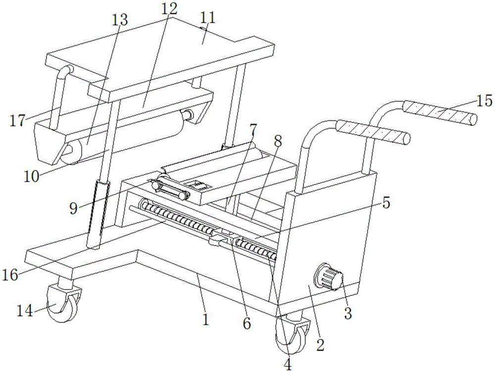
图1为本实用新型整体结构示意图;Fig. 1 is the overall structure schematic diagram of the present utility model;
图2为本实用新型主视图;Fig. 2 is the front view of the utility model;
图3为本实用新型清洁机构结构示意图。FIG. 3 is a schematic structural diagram of the cleaning mechanism of the present invention.
图中:1、T型支撑板;2、固定板;3、一号伺服电机;4、螺纹杆;5、L型固定架;6、移动套;7、连接板;8、移动槽;9、清洁机构;901、二号凹型架;902、安装槽;903、二号伺服电机;904、一号皮带轮;905、传动带;906、二号皮带轮;907、转动杆;908、清洁辊;909、刮板;10、气缸;11、T型安装板;12、一号凹型架;13、碾压辊;14、万向轮;15、辅助推杆;16、限位杆;17、L型安装杆。In the figure: 1. T-shaped support plate; 2. Fixed plate; 3. No. 1 servo motor; 4. Threaded rod; 5. L-shaped fixed frame; 6. Mobile sleeve; 7. Connecting plate; 8. Mobile groove; , Cleaning mechanism; 901, No. 2 concave frame; 902, Installation groove; 903, No. 2 servo motor; 904, No. 1 pulley; 905, Transmission belt; 906, No. 2 pulley; , scraper; 10, cylinder; 11, T-type mounting plate; 12, No. 1 concave frame; 13, rolling roller; 14, universal wheel; 15, auxiliary push rod; 16, limit rod; 17, L type Install the rod.
具体实施方式Detailed ways
下面将结合本实用新型实施例中的附图,对本实用新型实施例中的技术方案进行清楚、完整地描述,显然,所描述的实施例仅仅是本实用新型一部分实施例,而不是全部的实施例。基于本实用新型中的实施例,本领域普通技术人员在没有做出创造性劳动前提下所获得的所有其他实施例,都属于本实用新型保护的范围。The technical solutions in the embodiments of the present utility model will be clearly and completely described below with reference to the accompanying drawings in the embodiments of the present utility model. Obviously, the described embodiments are only a part of the embodiments of the present utility model, rather than all the implementations. example. Based on the embodiments of the present invention, all other embodiments obtained by those of ordinary skill in the art without creative work fall within the protection scope of the present invention.
实施例Example
如图1-图3所示,本实用新型一个实施例提出的一种土地整治用平整装置,包括T型支撑板1,T型支撑板1的顶部固定连接有固定板2,固定板2的一侧安装有一号伺服电机3,一号伺服电机3的输出端固定连接有螺纹杆4,螺纹杆4的另一端通过轴承连接有L型固定架5,L型固定架5的底部与T型支撑板1的顶部固定连接,螺纹杆4的表面螺纹连接有移动套6,移动套6的顶部固定连接有连接板7,L型固定架5的顶部设有连通的移动槽8,移动槽8的内壁与连接板7的表面滑动连接,连接板7的顶部设有清洁机构9,固定板2的顶部固定安装有气缸10,气缸10的输出端固定连接有T型安装板11,T型安装板11的底部下方设有一号凹型架12,一号凹型架12的内壁通过转轴连接有碾压辊13,通过一号伺服电机3的启动,是为了使得螺纹杆4表面的移动套6,能够随着螺纹杆4的转动下,移动套6可以在螺纹杆4的表面进行调节,这样移动套6顶部的连接板7,可以带动清洁机构9在L型固定架5的上方分别进行水平往返的直线运动,而碾压辊13在气缸10的作用下,能够调节碾压辊13与清洁辊908之间的位置,从而可以配合该清洁辊908对碾压辊13表面泥土进行有效处理,以提高碾压辊13对土地平整的效率。As shown in FIGS. 1 to 3 , a leveling device for land remediation proposed by an embodiment of the present invention includes a T-shaped support plate 1 , and a
如图3所示,在一些实施例中,清洁机构9包括二号凹型架901,二号凹型架901的底部与连接板7的顶部固定连接,二号凹型架901的表面设有连通的安装槽902,安装槽902的内壁安装有二号伺服电机903,二号伺服电机903的输出端固定连接有一号皮带轮904,一号皮带轮904的表面连接有相适配的传动带905,传动带905的内表面连接有相适配的二号皮带轮906,二号皮带轮906的内部固定连接有转动杆907,转动杆907的另一端通过轴承与二号凹型架901的内壁连接,转动杆907的表面固定连接有清洁辊908,清洁辊908的表面均布设有刮板909,通过二号伺服电机903在启动时,一号皮带轮904、传动带905和二号皮带轮906之间相互传动,是为了带动转动杆907表面的清洁辊908能够进行旋转,这样设计的目的,是为了当该清洁辊908移动到碾压辊13的表面前时,清洁辊908表面的刮板909在清洁辊908的转动下,会对碾压辊13表面粘附的泥土进行刮取,从而实现碾压辊13表面泥土的清洁效果,以提高碾压辊13对土地平整的高效性。As shown in FIG. 3 , in some embodiments, the
如图1和图2所示,在一些实施例中,T型支撑板1的底部固定安装有万向轮14,万向轮14的数量为三个,通过在T型支撑板1底部设计三个万向轮14,则是根据T型支撑板1的表面形状所进行设计的,这样可以保证该装置在万向轮14的移动下,能够高效配合碾压辊13对土地进行平整。As shown in FIG. 1 and FIG. 2 , in some embodiments,
如图1和图2所示,在一些实施例中,固定板2的顶部固定连接有两个对称的辅助推杆15,辅助推杆15的表面设有橡胶套,通过辅助推杆15和橡胶套设计,主要是为了对该装置在万向轮14的移动下,能够便于对该该装置进行推动,从而提高该装置的便携性。As shown in FIG. 1 and FIG. 2 , in some embodiments, two symmetrical
如图1所示,在一些实施例中,L型固定架5的内侧壁固定连接有限位杆16,限位杆16的表面与移动套6的内部滑动连接,限位杆16的另一端与固定板2相对的一端固定连接,通过限位杆16的设计,主要用于对移动套6进行限位,以保证移动套6能够在螺纹杆4的表面滑动稳定滑行,从而可以更好的配合清洁机构9对碾压辊13表面的泥土进行清理。As shown in FIG. 1 , in some embodiments, the inner side wall of the L-
如图1所示,在一些实施例中,一号凹型架12的顶部固定连接有两个对称的L型安装杆17,L型安装杆17的另一端与T型安装板11的表面固定连接,通过L型安装杆17,是为了便于对一号凹型架12进行固定限位,以保证一号凹型架12内壁中的碾压辊13,在对土地进行平整时,可以提高稳定性。As shown in FIG. 1 , in some embodiments, two symmetrical L-shaped mounting
最后应说明的是:以上所述仅为本实用新型的优选实施例而已,并不用于限制本实用新型,尽管参照前述实施例对本实用新型进行了详细的说明,对于本领域的技术人员来说,其依然可以对前述各实施例所记载的技术方案进行修改,或者对其中部分技术特征进行等同替换。凡在本实用新型的精神和原则之内,所作的任何修改、等同替换、改进等,均应包含在本实用新型的保护范围之内。Finally, it should be noted that the above are only the preferred embodiments of the present invention, and are not intended to limit the present invention. , it is still possible to modify the technical solutions described in the foregoing embodiments, or perform equivalent replacements to some of the technical features. Any modification, equivalent replacement, improvement, etc. made within the spirit and principle of the present invention shall be included in the protection scope of the present invention.
Claims (6)
Priority Applications (1)
| Application Number | Priority Date | Filing Date | Title |
|---|---|---|---|
| CN202220820635.6U CN217037849U (en) | 2022-04-11 | 2022-04-11 | Land reclamation is with leveling device |
Applications Claiming Priority (1)
| Application Number | Priority Date | Filing Date | Title |
|---|---|---|---|
| CN202220820635.6U CN217037849U (en) | 2022-04-11 | 2022-04-11 | Land reclamation is with leveling device |
Publications (1)
| Publication Number | Publication Date |
|---|---|
| CN217037849U true CN217037849U (en) | 2022-07-26 |
Family
ID=82470635
Family Applications (1)
| Application Number | Title | Priority Date | Filing Date |
|---|---|---|---|
| CN202220820635.6U Expired - Fee Related CN217037849U (en) | 2022-04-11 | 2022-04-11 | Land reclamation is with leveling device |
Country Status (1)
| Country | Link |
|---|---|
| CN (1) | CN217037849U (en) |
Cited By (1)
| Publication number | Priority date | Publication date | Assignee | Title |
|---|---|---|---|---|
| CN119790738A (en) * | 2025-01-03 | 2025-04-11 | 中国农业大学 | A furrowing and seed-burying device convenient for irrigation and sowing |
-
2022
- 2022-04-11 CN CN202220820635.6U patent/CN217037849U/en not_active Expired - Fee Related
Cited By (1)
| Publication number | Priority date | Publication date | Assignee | Title |
|---|---|---|---|---|
| CN119790738A (en) * | 2025-01-03 | 2025-04-11 | 中国农业大学 | A furrowing and seed-burying device convenient for irrigation and sowing |
Similar Documents
| Publication | Publication Date | Title |
|---|---|---|
| CN222294615U (en) | A compacting device | |
| CN113355999A (en) | Road and bridge crack flattening prosthetic devices that building engineering used | |
| CN209816621U (en) | Marking clearing device for municipal construction | |
| CN211850916U (en) | A multifunctional concrete trowel that can be laid with film | |
| CN211734982U (en) | Be used for mud flat ground geotechnique cloth laying device | |
| CN218667856U (en) | Inside mediation structure of municipal administration pipeline | |
| CN221670355U (en) | A mobile and convenient land crushing and leveling device | |
| CN217949202U (en) | Land leveling device | |
| CN221297505U (en) | Highway construction leveling equipment | |
| CN222100987U (en) | A ground leveling device for land acquisition | |
| CN221461162U (en) | Foundation leveling equipment for constructional engineering | |
| CN223343235U (en) | A water conservancy project channel construction leveling device | |
| CN211772603U (en) | Rolling machine for road engineering | |
| CN221052306U (en) | Road surface finishing equipment | |
| CN217948676U (en) | Roadbed and pavement rolling machine | |
| CN223813676U (en) | Road surface evener with dust-proof mechanism | |
| CN223386500U (en) | Permeable concrete pavement construction pavement leveling device | |
| CN222184154U (en) | A leveling device | |
| CN221855486U (en) | Ground leveling equipment | |
| CN221323575U (en) | Water-free dust treatment device | |
| CN212086872U (en) | Chinese-medicinal material is planted with device that loosens soil | |
| CN218779560U (en) | Silt clean-up equipment for hydraulic engineering | |
| CN220468549U (en) | Compacting device for pavement | |
| CN223675083U (en) | Roadbed molding compaction equipment | |
| CN223281152U (en) | Land leveling device for land engineering |
Legal Events
| Date | Code | Title | Description |
|---|---|---|---|
| GR01 | Patent grant | ||
| GR01 | Patent grant | ||
| CF01 | Termination of patent right due to non-payment of annual fee | ||
| CF01 | Termination of patent right due to non-payment of annual fee |
Granted publication date: 20220726 |