CN217021391U - Screw spindle cooling device of extruder - Google Patents
Screw spindle cooling device of extruder Download PDFInfo
- Publication number
- CN217021391U CN217021391U CN202220157009.3U CN202220157009U CN217021391U CN 217021391 U CN217021391 U CN 217021391U CN 202220157009 U CN202220157009 U CN 202220157009U CN 217021391 U CN217021391 U CN 217021391U
- Authority
- CN
- China
- Prior art keywords
- screw
- cooling
- box
- cooling device
- pipe
- Prior art date
- Legal status (The legal status is an assumption and is not a legal conclusion. Google has not performed a legal analysis and makes no representation as to the accuracy of the status listed.)
- Active
Links
- 238000001816 cooling Methods 0.000 title claims abstract description 62
- 239000007788 liquid Substances 0.000 claims description 39
- 238000001125 extrusion Methods 0.000 claims description 24
- 238000007789 sealing Methods 0.000 claims description 12
- 230000001681 protective effect Effects 0.000 claims description 4
- 230000000149 penetrating effect Effects 0.000 claims description 3
- 230000000694 effects Effects 0.000 abstract description 15
- 239000002994 raw material Substances 0.000 abstract description 10
- 230000017525 heat dissipation Effects 0.000 abstract description 3
- 239000000110 cooling liquid Substances 0.000 abstract description 2
- 239000002826 coolant Substances 0.000 description 16
- 238000005086 pumping Methods 0.000 description 5
- 238000003756 stirring Methods 0.000 description 2
- 230000009286 beneficial effect Effects 0.000 description 1
- 230000007613 environmental effect Effects 0.000 description 1
- 239000000463 material Substances 0.000 description 1
- 230000002035 prolonged effect Effects 0.000 description 1
- 238000010992 reflux Methods 0.000 description 1
Images



Landscapes
- Extrusion Moulding Of Plastics Or The Like (AREA)
Abstract
The utility model discloses a screw spindle cooling device of an extruder, relates to the field of extruders, and aims at solving the problem that the cooling effect of the existing cooling device for screws of the extruder is poor. The cooling device is novel in structure, and the cooling liquid is enabled to flow along the inner wall of the screw to take away heat generated by the screw through the arrangement of the cooling device, so that the effect of heat dissipation and cooling is achieved, the heat generated by the screw is avoided, and the quality of certain raw materials is damaged.
Description
Technical Field
The utility model relates to the field of extruders, in particular to a screw spindle cooling device of an extruder.
Background
In the plastic extrusion molding equipment, the plastic extruder is generally called a main machine, and the subsequent equipment matched with the plastic extruder is called an auxiliary machine. After the development of the plastic extruder for more than 100 years, multiple types of double screws, multiple screws, even no screws and the like are derived from the original single screw, when the extruder works, a large amount of internal energy is generated due to the extrusion friction between the screws and materials, the quality of certain temperature-sensitive raw materials can be damaged by high temperature, and the quality of products is reduced, so that the screws are usually provided with cooling devices when in use.
However, the cooling effect of the cooling device for the screw of the existing extruder is poor, the using effect of equipment is affected, and the quality of certain raw materials is easily damaged. Therefore, in order to solve the above problems, we propose a cooling device for the screw main shaft of an extruder.
SUMMERY OF THE UTILITY MODEL
The utility model provides a screw spindle cooling device of an extruder, which solves the problem of poor cooling effect of the existing cooling device for the screw of the extruder.
In order to achieve the purpose, the utility model adopts the following technical scheme:
the utility model provides a screw rod main shaft cooling device of extruder, includes the base and extrudes the pipe, base top fixed mounting has two mount pads that are the symmetric distribution, and two mount pad top fixed mounting has the extrusion pipe, extrusion pipe one side fixed mounting has the protection box, just extrude intraductal rotation and install the screw rod, the screw rod is close to protection box one end and rotates and run through the protection box, just the screw rod runs through protection box one end fixed mounting and has the cooler bin, the cooler bin is kept away from screw rod one end and is rotated and run through the protection box, just the inside hollow structure that is of screw rod, be equipped with cooling device in the screw rod, just the screw rod runs through protection box one end lateral wall and is equipped with drive arrangement.
Preferably, cooling device includes drawing liquid pump, catheter, cooling pan and back flow, fixed mounting has the cooling pan in the cooling box, just the cooling pan is netted, fixed mounting has the drawing liquid pump in the cooling box, just the drawing liquid pump is close to and extrudes a pipe one end fixedly connected with catheter, drawing liquid pump one end is kept away from to the catheter extends to inside the screw rod, just the cooling box is close to and extrudes pipe one side inner wall fixed mounting and has the back flow, the back flow is kept away from drawing liquid pump one end and is run through the screw rod, just be equipped with sealing device in the back flow.
Preferably, sealing device includes dog, closing plate and resistance spring, back flow top lateral wall articulates there is the closing plate, just back flow bottom inner wall fixed mounting has the dog, be close to one side fixedly connected with resistance spring that cooler bin one end top inner wall is relative with the closing plate, just resistance spring is the slope setting.
Preferably, drive arrangement includes step motor, drive gear, driven gear and a piece, protection box bottom inner wall fixed mounting has a piece, just a piece top fixed mounting has step motor, the fixed cover of step motor output shaft is equipped with drive gear, just the screw rod runs through the fixed cover of protection box one end lateral wall and is equipped with driven gear, just drive gear and driven gear meshing.
Preferably, the extrusion pipe is close to protection box one end lateral wall fixed mounting and has the feeder hopper, just the extrusion pipe is kept away from protection box one side and is seted up the extrusion hole that is the ring array and distributes.
Preferably, the inner wall of the screw is fixedly provided with a heat conducting fin.
The utility model has the beneficial effects that:
1. through cooling device's setting, in injecting the screw rod with the coolant liquid through the drawing liquid pump, make the coolant liquid take away the heat that the screw rod produced, the screw rod inner wall is equipped with the conducting strip, heat and coolant liquid mix with higher speed, the heat dissipation efficiency is improved, the coolant liquid passes through in the back flow reentrant cooling tank, through cooling disc cooling, utilize the cooperation of catheter and back flow, make the continuous renewal of coolant liquid in the screw rod take away the heat, reach high-efficient radiating effect, the service life of equipment has been prolonged, and make coolant liquid recycle, energy saving and environmental protection.
2. Through sealing device's setting, through the cooperation of dog, closing plate and resistance spring, in making carry thermal coolant liquid entering cooler bin in the screw rod, prevented the cooling reflux, improved the practicality of equipment, and through drive arrangement's setting, utilize step motor drive screw to rotate, reach the effect of stirring raw materials promptly, and play the effect of carrying the raw materials, reach the effect of extruding the product.
In conclusion, the equipment has a novel structure, and through the arrangement of the cooling device, the cooling liquid is enabled to flow along the inner wall of the screw to take away heat generated by the screw, so that the heat dissipation and cooling effects are achieved, the screw is prevented from generating heat, the quality of certain raw materials is damaged, and the quality of products is improved.
Drawings
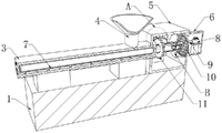
FIG. 1 is a schematic view of the structure of the present invention;
FIG. 2 is a cross-sectional view of the present invention;
FIG. 3 is an enlarged view of A of FIG. 2 according to the present invention;
FIG. 4 is an enlarged view of B of FIG. 2 according to the present invention;
FIG. 5 is an exploded view of the drive of the present invention;
fig. 6 is an exploded view of the sealing device of the present invention.
The reference numbers in the figures: 1. a base; 2. a mounting base; 3. extruding a pipe; 4. a feed hopper; 5. a protective box; 6. a cooling tank; 7. a screw; 8. a support block; 9. a catheter; 10. a cooling pan; 11. a driven gear; 12. a stepping motor; 13. a drive gear; 14. a return pipe; 15. a stopper; 16. a sealing plate; 17. a resistance spring; 18. and (7) supporting the blocks.
Detailed Description
The technical solutions in the embodiments of the present invention will be clearly and completely described below with reference to the drawings in the embodiments of the present invention, and it is obvious that the described embodiments are only a part of the embodiments of the present invention, and not all of the embodiments.
Referring to fig. 1-3 and 5, a screw spindle cooling device of an extruder comprises a base 1 and an extrusion tube 3, wherein a feed hopper 4 is fixedly installed on the side wall of one end of the extrusion tube 3 close to a protection box 5, when the device is used, a worker injects raw materials into the extrusion tube 3 from the feed hopper 4, two symmetrically distributed mounting seats 2 are fixedly installed on the top end of the base 1, the extrusion tube 3 is fixedly installed on the top ends of the two mounting seats 2, a protection box 5 is fixedly installed on one side of the extrusion tube 3, a screw 7 is rotatably installed in the extrusion tube 3, one end of the screw 7 close to the protection box 5 rotatably penetrates through the protection box 5, a driving device is arranged on the side wall of one end of the screw 7 penetrating through the protection box 5, the driving device comprises a stepping motor 12, a driving gear 13, a driven gear 11 and a support block 18, a support block 18 is fixedly installed on the inner wall of the bottom end of the protection box 5, and a stepping motor 12 is fixedly installed on the top end of the support block 18, fixed cover of step motor 12 output shaft is equipped with drive gear 13, and the fixed cover of 5 one end lateral walls of protection box is run through to screw 7 is equipped with driven gear 11, and drive gear 13 and the meshing of driven gear 11, and extrude pipe 3 and keep away from 5 one side of protection box and offer the hole of extruding that is the annular array and distribute, and simultaneously, drive gear 13 rotates through step motor 12 drive gear 13, drive gear 13 drive driven gear 11 rotates, 11 drive screw 7 of driven gear rotate, reach the effect of stirring transport raw materials, make the raw materials through extruding the hole, reach the effect of processing product.
Referring to fig. 1-2, a cooling box 6 is fixedly installed at one end of a screw 7 penetrating through a protection box 5, one end of the cooling box 6, which is far away from the screw 7, rotatably penetrates through the protection box 5, the interior of the screw 7 is of a hollow structure, a cooling device is arranged in the screw 7, the cooling device comprises a liquid pumping pump 8, a liquid guide pipe 9, a cooling disc 10 and a backflow pipe 14, the cooling disc 10 is fixedly installed in the cooling box 6, the liquid pumping pump 8 is fixedly installed in the cooling box 6, the liquid guide pipe 9 is fixedly connected to one end, which is close to an extrusion pipe 3, of the liquid pumping pump 8, the end, which is far away from the liquid pumping pipe 9, of the liquid guide pipe 9 extends into the interior of the screw 7, the backflow pipe 14 is fixedly installed on the inner wall of one side, which is close to the extrusion pipe 3, of the backflow pipe 14, which is far away from the end, which is far away from the liquid pumping pump 8, penetrates through the screw 7, a sealing device is arranged in the backflow pipe 14, and a heat conducting sheet is fixedly installed on the inner wall of the screw 7, when the device is used, screw 7 rubs with the raw materials for a long time, 7 surfaces of screw can produce the heat, the heat is inside through leading-in screw 7 of conducting strip, and simultaneously, through the leading-in catheter 9 of coolant liquid in drawing liquid pump 8 with cooler bin 6, the coolant liquid flows into inside 7 of screw through catheter 9, take away the heat through the coolant liquid, heat and coolant liquid mix the back, the coolant liquid that has the heat is under the promotion of the coolant liquid of constantly newly injecting into, get into cooler bin 6 once more through back flow 14, cool down through cooling disc 10, impel the inside cold and hot exchange of screw 7, reach the radiating effect of cooling down, the radiating efficiency is improved, and the processingquality of product has been improved.
Referring to fig. 2, fig. 4 and fig. 6, sealing device includes dog 15, closing plate 16 and resistance spring 17, 14 top lateral walls of back flow have closing plate 16 to articulate, and 14 bottom inner walls fixed mounting of back flow have dog 15, be close to 6 one end top inner walls of cooler bin and the relative one side fixedly connected with resistance spring 17 of closing plate 16, and resistance spring 17 is the slope setting, the coolant liquid that has the heat is under the promotion of the coolant liquid of constantly newly pouring into, cause closing plate 16 slope, make the coolant liquid flow back smoothly, when equipment does not use, closing plate 16 resumes the normal position under resistance spring 17's effect, reach the effect of sealed back flow 14, the practicality of equipment has been improved.
The above description is only for the preferred embodiment of the present invention, but the scope of the present invention is not limited thereto, and any person skilled in the art should be considered as the technical solutions and the utility model concepts of the present invention in the scope of the present invention.
Claims (6)
1. A screw spindle cooling device of an extruder comprises a base (1) and an extrusion pipe (3), it is characterized in that two symmetrically distributed mounting seats (2) are fixedly mounted at the top end of the base (1), and the top ends of the two mounting seats (2) are fixedly provided with an extrusion pipe (3), one side of the extrusion pipe (3) is fixedly provided with a protection box (5), a screw rod (7) is rotatably arranged in the extrusion pipe (3), one end of the screw rod (7) close to the protective box (5) is rotatably penetrated through the protective box (5), and a cooling box (6) is fixedly arranged at one end of the screw (7) penetrating through the protective box (5), one end of the cooling box (6) far away from the screw (7) is rotatably penetrated through the protection box (5), the screw (7) is of a hollow structure, a cooling device is arranged in the screw (7), and the screw rod (7) penetrates through the side wall of one end of the protection box (5) and is provided with a driving device.
2. The cooling device of a screw main shaft of an extruder according to claim 1, the cooling device comprises a liquid pump (8), a liquid guide pipe (9), a cooling disc (10) and a return pipe (14), the cooling disc (10) is fixedly arranged in the cooling box (6), the cooling disc (10) is in a net shape, a liquid pump (8) is fixedly arranged in the cooling box (6), and one end of the liquid pump (8) close to the extrusion pipe (3) is fixedly connected with a liquid guide pipe (9), one end of the liquid guide pipe (9) far away from the liquid pump (8) extends into the screw rod (7), a return pipe (14) is fixedly arranged on the inner wall of one side of the cooling box (6) close to the extrusion pipe (3), one end of the return pipe (14) far away from the liquid pump (8) penetrates through the screw rod (7), and a sealing device is arranged in the return pipe (14).
3. The cooling device for the main shaft of the screw of the extruder is characterized in that the sealing device comprises a stop block (15), a sealing plate (16) and a resistance spring (17), the sealing plate (16) is hinged to the side wall of the top end of the return pipe (14), the stop block (15) is fixedly installed on the inner wall of the bottom end of the return pipe (14), the resistance spring (17) is fixedly connected to the side, opposite to the sealing plate (16), of the inner wall of the top end of one end of the cooling box (6), and the resistance spring (17) is arranged in an inclined mode.
4. The screw spindle cooling device of an extruder according to claim 1, wherein the driving device comprises a stepping motor (12), a driving gear (13), a driven gear (11) and a support block (18), the inner wall of the bottom end of the protection box (5) is fixedly provided with the support block (18), the top end of the support block (18) is fixedly provided with the stepping motor (12), the output shaft of the stepping motor (12) is fixedly sleeved with the driving gear (13), the screw (7) penetrates through the side wall of one end of the protection box (5) and is fixedly sleeved with the driven gear (11), and the driving gear (13) is meshed with the driven gear (11).
5. The screw spindle cooling device of the extruder according to claim 1, wherein a feed hopper (4) is fixedly mounted on a side wall of one end of the extrusion pipe (3) close to the protection box (5), and extrusion holes distributed in an annular array are formed in one side of the extrusion pipe (3) far away from the protection box (5).
6. Screw spindle cooling device according to claim 1, characterised in that the inner wall of the screw (7) is fixedly provided with heat conducting fins.
Priority Applications (1)
| Application Number | Priority Date | Filing Date | Title |
|---|---|---|---|
| CN202220157009.3U CN217021391U (en) | 2022-01-20 | 2022-01-20 | Screw spindle cooling device of extruder |
Applications Claiming Priority (1)
| Application Number | Priority Date | Filing Date | Title |
|---|---|---|---|
| CN202220157009.3U CN217021391U (en) | 2022-01-20 | 2022-01-20 | Screw spindle cooling device of extruder |
Publications (1)
| Publication Number | Publication Date |
|---|---|
| CN217021391U true CN217021391U (en) | 2022-07-22 |
Family
ID=82449473
Family Applications (1)
| Application Number | Title | Priority Date | Filing Date |
|---|---|---|---|
| CN202220157009.3U Active CN217021391U (en) | 2022-01-20 | 2022-01-20 | Screw spindle cooling device of extruder |
Country Status (1)
| Country | Link |
|---|---|
| CN (1) | CN217021391U (en) |
Cited By (2)
| Publication number | Priority date | Publication date | Assignee | Title |
|---|---|---|---|---|
| CN115549378A (en) * | 2022-10-11 | 2022-12-30 | 南京高精齿轮集团有限公司 | Drive device and extruder |
| CN116551964A (en) * | 2023-07-10 | 2023-08-08 | 山东圣和薄膜新材料有限公司 | Cold circulation system of extruder |
-
2022
- 2022-01-20 CN CN202220157009.3U patent/CN217021391U/en active Active
Cited By (3)
| Publication number | Priority date | Publication date | Assignee | Title |
|---|---|---|---|---|
| CN115549378A (en) * | 2022-10-11 | 2022-12-30 | 南京高精齿轮集团有限公司 | Drive device and extruder |
| CN116551964A (en) * | 2023-07-10 | 2023-08-08 | 山东圣和薄膜新材料有限公司 | Cold circulation system of extruder |
| CN116551964B (en) * | 2023-07-10 | 2023-09-19 | 山东圣和薄膜新材料有限公司 | Cold circulation system of extruder |
Similar Documents
| Publication | Publication Date | Title |
|---|---|---|
| CN216968617U (en) | Quick refrigerated single wall bellows production line | |
| CN116118144A (en) | Double-screw plastic extruder | |
| CN214082667U (en) | Constant-temperature cooling device of injection molding machine | |
| CN220075539U (en) | Energy-saving plastic bottle production blow molding machine | |
| CN212422079U (en) | Cooling device for injection molding machine | |
| CN117507215B (en) | Curtain coating membrane curtain coating make-up machine | |
| CN220973297U (en) | Water-cooling guiding device | |
| CN219522983U (en) | Extruder with cooling function | |
| CN219214050U (en) | Extrusion molding device with guiding function for processing high polymer material | |
| CN217622117U (en) | Temperature control device of plastic extruding machine for producing extruded sheet | |
| CN213675366U (en) | Water-cooling material guide device for extruder | |
| CN213860595U (en) | A high-efficiency bamboo powder toothbrush handle extrusion molding equipment | |
| CN212707505U (en) | Extruder cooling trough with good cooling effect | |
| CN215040141U (en) | Cooling device for color masterbatch plastic strip | |
| CN224240288U (en) | TPU film tape casting extrusion device | |
| CN213441092U (en) | Screw temperature control system for film blowing machine | |
| CN223604960U (en) | Polyurethane hold-in range extrusion molding equipment | |
| CN223644213U (en) | A cooling structure for a straw extruder | |
| CN223236915U (en) | PE pipe extrusion shaping device and PE pipe production line | |
| CN221437189U (en) | Cold circulation system of extruder | |
| CN222451267U (en) | A device for preparing yellowing-resistant and highly transparent label film | |
| CN213261027U (en) | Cooling device for plastic extruder | |
| CN223558795U (en) | Pp plastic granule granulator | |
| CN224240320U (en) | Double-screw extrusion granulating equipment | |
| CN216230664U (en) | Plastic film produces extruder |
Legal Events
| Date | Code | Title | Description |
|---|---|---|---|
| GR01 | Patent grant | ||
| GR01 | Patent grant |