CN216973114U - Novel safety barrier structure for highway bridge - Google Patents
Novel safety barrier structure for highway bridge Download PDFInfo
- Publication number
- CN216973114U CN216973114U CN202220340213.9U CN202220340213U CN216973114U CN 216973114 U CN216973114 U CN 216973114U CN 202220340213 U CN202220340213 U CN 202220340213U CN 216973114 U CN216973114 U CN 216973114U
- Authority
- CN
- China
- Prior art keywords
- joint
- barrier structure
- safety barrier
- clamping grooves
- screw hole
- Prior art date
- Legal status (The legal status is an assumption and is not a legal conclusion. Google has not performed a legal analysis and makes no representation as to the accuracy of the status listed.)
- Expired - Fee Related
Links
- 230000004888 barrier function Effects 0.000 title claims description 9
- 230000001681 protective effect Effects 0.000 claims description 8
- 229920000742 Cotton Polymers 0.000 claims description 2
- 238000003466 welding Methods 0.000 abstract 1
- 238000009434 installation Methods 0.000 description 8
- 230000006378 damage Effects 0.000 description 6
- 239000006260 foam Substances 0.000 description 3
- XEEYBQQBJWHFJM-UHFFFAOYSA-N Iron Chemical compound [Fe] XEEYBQQBJWHFJM-UHFFFAOYSA-N 0.000 description 2
- 230000000694 effects Effects 0.000 description 2
- 208000027418 Wounds and injury Diseases 0.000 description 1
- 230000009286 beneficial effect Effects 0.000 description 1
- 208000014674 injury Diseases 0.000 description 1
- 229910052742 iron Inorganic materials 0.000 description 1
- 238000012423 maintenance Methods 0.000 description 1
- 238000012986 modification Methods 0.000 description 1
- 230000004048 modification Effects 0.000 description 1
- 238000006748 scratching Methods 0.000 description 1
- 230000002393 scratching effect Effects 0.000 description 1
- 238000002791 soaking Methods 0.000 description 1
- 238000006467 substitution reaction Methods 0.000 description 1
Images

Landscapes
- Refuge Islands, Traffic Blockers, Or Guard Fence (AREA)
Abstract
The utility model discloses a novel safety guardrail structure for a highway bridge, which relates to the technical field of guardrails and is characterized in that: the automatic welding machine comprises two bases, wherein the tops of the two bases are provided with first clamping grooves, vertical rods are clamped in the clamping grooves, one sides of the two vertical rods are provided with two second clamping grooves, cross rods are clamped in the second clamping grooves, the other ends of the cross rods are clamped with corresponding second clamping grooves in the other vertical rod, a plurality of grid rods are arranged between the two cross rods, the bases are provided with first threaded holes, and the bottoms of the vertical rods are provided with second threaded holes matched with the first threaded holes; the utility model is convenient to replace and maintain and reduces the replacement cost.
Description
Technical Field
The utility model relates to the technical field of guardrails, in particular to a novel safety guardrail structure for a highway bridge.
Background
The guardrail is the iron fence that sets up between roadside or pavement and lane, both sides at highway and bridge generally all are provided with the guardrail, its purpose is in order to prevent that the vehicle out of control from crossing the highway, outside the bridge, take place unexpected injury oneself or passerby, have the guard action that makes the vehicle can not break through, wear down, cross highway and bridge, and can beautify the city, guardrail factor of safety of using at present is not high, it is too fast when the vehicle speed, take place the vertically collision with the guardrail, the guardrail fracture often can appear, the condition that the vehicle rushes out the bridge, the guardrail of prior art adopts fixed structure, the inconvenient maintenance of guardrail damage back is changed.
SUMMERY OF THE UTILITY MODEL
The utility model aims to provide a novel safety guardrail structure for a highway bridge, which is convenient to replace and maintain and reduces the replacement cost.
In order to realize the purpose, the utility model provides the following technical scheme:
the utility model provides a novel safety barrier structure for public road bridge roof beam, includes two bases, two open at the base top has first joint groove, the joint inslot joint has the pole setting, two second joint grooves have all been opened to pole setting one side, second joint inslot joint has the horizontal pole, the horizontal pole other end and another pole setting on correspond second joint groove looks joint, two be equipped with a plurality of bars poles between the horizontal pole, it has first screw hole to open on the base, open the pole setting bottom has the second screw hole that suits with first screw hole.
By adopting the scheme, when the guardrail needs to be installed, the two ends of the cross rod are firstly clamped into the second clamping grooves in the vertical rods, then the bottom ends of the vertical rods are clamped into the first clamping grooves in the base, and then the base and the vertical rods are fixed together through the fixing bolts, the first threaded holes and the second threaded holes, so that the installation can be completed, and the guardrail is convenient to install, simple and rapid; when the guardrail is damaged, the damaged part is detached according to the opposite flow during installation, the damaged part is taken down, a new part is replaced, and the guardrail can be installed again without whole replacement, so that the frequency and trouble of replacing the base are reduced, and only part of the part needs to be replaced, so that the replacement cost is reduced.
Preferably, one side of the cross rod is provided with a plurality of third clamping grooves matched with the fence rods.
Preferably, two sides of the two vertical rods are provided with buffer plates, two ends of each buffer plate are respectively connected with the two vertical rods, the two vertical rods are provided with a plurality of through third threaded holes, and two ends of each buffer plate are provided with fourth threaded holes matched with the third threaded holes.
Preferably, the buffer board comprises a rubber protective sleeve, and foam is arranged in the rubber protective sleeve.
Preferably, the outer side of the rubber protective sleeve is provided with a wear-resistant layer.
The utility model has the following beneficial effects:
when the guardrail needs to be installed, the two ends of the cross rod are clamped into the second clamping grooves in the vertical rods, the bottom ends of the vertical rods are clamped into the first clamping grooves in the base, and the base and the vertical rods are fixed together through the fixing bolts, the first threaded holes and the second threaded holes, so that the installation can be completed, and the installation is convenient, simple and rapid; when the guardrail is damaged, the damaged part is detached according to the opposite flow during installation, the damaged part is taken down, a new part is replaced, and the guardrail can be installed again without whole replacement, so that the frequency and trouble of replacing the base are reduced, and only part of the part needs to be replaced, so that the replacement cost is reduced.
Drawings
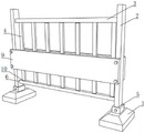
FIG. 1 is a schematic perspective view of an embodiment of the present invention;
FIG. 2 is a side cross-sectional view of an embodiment of the utility model.
In the figure: 1. a base; 2. erecting a rod; 3. a cross bar; 4. a railing bar; 5. a first clamping groove; 6. a second clamping groove; 71. a first threaded hole; 72. a second threaded hole; 81. a third threaded hole; 82. a fourth threaded hole; 9. a buffer plate; 91. a rubber protective sleeve; 92. soaking cotton; 93. a wear layer; 10. and a third clamping groove.
Detailed Description
The utility model is described in further detail below with reference to the drawings and the detailed description.
The utility model provides a novel safety barrier structure for public road bridge roof beam, as shown in fig. 1-2, including two bases 1, open at two bases 1 tops has first joint groove 5, the joint inslot joint has pole setting 2, two second joint grooves 6 have all been opened to 2 one sides in two pole settings, the joint has horizontal pole 3 in the second joint groove 6, the 3 other ends of horizontal pole and the 6 looks joints in the corresponding second joint groove of another pole setting 2, be equipped with a plurality of bars railing 4 between two horizontal poles 3, open on the base 1 has first screw hole 71, open the 2 bottoms in pole setting has the second screw hole 72 that suits with first screw hole 71.
As shown in fig. 1-2, when the guardrail needs to be installed, firstly, two ends of the cross rod 3 are clamped into the second clamping grooves 6 on the upright rods 2, then the bottom ends of the upright rods 2 are clamped into the first clamping grooves 5 on the base 1, and then the base 1 and the upright rods 2 are fixed together through the fixing bolts, the first threaded holes 71 and the second threaded holes 72, so that the installation can be completed, and the installation is convenient, simple and rapid; after this guardrail damages, dismantle according to opposite flow when the installation, take off and damage the part, change new part, the reinstallation can, need not whole replacement, reduced the frequency and the trouble of changing base 1 to only need to change partial part, reduced the replacement cost.
As shown in fig. 1-2, one side of the cross bar 3 is provided with a plurality of third clamping grooves 10 corresponding to the fence rods 4, and the fence rods 4 can be clamped or removed independently, so that the replacement cost is further reduced.
As shown in fig. 1-2, two sides of the two upright posts 2 are provided with the buffer plates 9, two ends of each buffer plate 9 are respectively connected with the two upright posts 2, the two upright posts 2 are provided with a plurality of through third threaded holes 81, two ends of each buffer plate 9 are provided with fourth threaded holes 82 corresponding to the third threaded holes 81, and the buffer plates 9 are arranged on two sides of the upright posts 2 through fixing bolts, the third threaded holes 81 and the fourth threaded holes 82, so that the buffer capacity is improved, and the damage to vehicles and guardrails is reduced.
As shown in fig. 1-2, the buffer board 9 includes a rubber protection sleeve 91, foam 92 is disposed in the rubber protection sleeve 91, and the rubber and the foam 92 are durable, elastic and have a buffer effect.
As shown in fig. 1-2, the outer side of the rubber protective sleeve 91 is provided with a wear-resistant layer 93, so that scratching damage is reduced, and the durability of the guardrail is improved.
The above is only a specific embodiment of the present invention, but the technical features of the present invention are not limited thereto. Any simple changes, equivalent substitutions or modifications based on the present invention to solve the same technical problems and achieve the same technical effects are all covered by the protection scope of the present invention.
Claims (5)
1. The utility model provides a novel highway is safety barrier structure for bridge, includes two bases (1), its characterized in that: two open base (1) top has first joint groove (5), the joint has pole setting (2), two in first joint groove (5) the joint has two second joint groove (6) all opened pole setting (2) one side, the joint has horizontal pole (3) in second joint groove (6), corresponding second joint groove (6) looks joint on the horizontal pole (3) other end and another pole setting (2), two be equipped with a plurality of bars railing (4) between horizontal pole (3), it has first screw hole (71) to open on base (1), second screw hole (72) that suit with first screw hole (71) are opened to pole setting (2) bottom.
2. The novel safety barrier structure for road bridge of claim 1, wherein: and a plurality of third clamping grooves (10) which are matched with the fence rods (4) are formed in one side of the cross rod (3).
3. The novel safety barrier structure for road bridge of claim 1, wherein: two pole setting (2) both sides are installed buffer board (9), the both ends of buffer board (9) are connected with coexistence pole (2) respectively, two it has a plurality of third screw holes (81) that link up to open on pole setting (2), fourth screw hole (82) that suit with third screw hole (81) are opened at buffer board (9) both ends.
4. The novel safety barrier structure for road and bridge according to claim 3, wherein: buffer board (9) are equipped with cotton (92) of bubble including rubber protective sheath (91) in rubber protective sheath (91).
5. The novel safety barrier structure for road and bridge according to claim 4, wherein: and a wear-resistant layer (93) is arranged on the outer side of the rubber protective sleeve (91).
Priority Applications (1)
| Application Number | Priority Date | Filing Date | Title |
|---|---|---|---|
| CN202220340213.9U CN216973114U (en) | 2022-02-18 | 2022-02-18 | Novel safety barrier structure for highway bridge |
Applications Claiming Priority (1)
| Application Number | Priority Date | Filing Date | Title |
|---|---|---|---|
| CN202220340213.9U CN216973114U (en) | 2022-02-18 | 2022-02-18 | Novel safety barrier structure for highway bridge |
Publications (1)
| Publication Number | Publication Date |
|---|---|
| CN216973114U true CN216973114U (en) | 2022-07-15 |
Family
ID=82354089
Family Applications (1)
| Application Number | Title | Priority Date | Filing Date |
|---|---|---|---|
| CN202220340213.9U Expired - Fee Related CN216973114U (en) | 2022-02-18 | 2022-02-18 | Novel safety barrier structure for highway bridge |
Country Status (1)
| Country | Link |
|---|---|
| CN (1) | CN216973114U (en) |
-
2022
- 2022-02-18 CN CN202220340213.9U patent/CN216973114U/en not_active Expired - Fee Related
Similar Documents
| Publication | Publication Date | Title |
|---|---|---|
| CN205046948U (en) | Construction of road garden district is with protection rail | |
| CN215052475U (en) | Traffic road protective fence | |
| CN215518404U (en) | Anti-falling device for bridge construction | |
| CN205242308U (en) | Strenghthened type road guardrail with wave form roof beam and crossbeam | |
| CN211596568U (en) | Novel road and bridge protection device | |
| CN212000764U (en) | Green's guardrail that municipal construction engineering safety used | |
| CN209989736U (en) | Guardrail in middle of town road | |
| CN209854555U (en) | Novel public road bridge safety protection structure for roof beam | |
| CN219490787U (en) | Guardrail transformation lifting structure | |
| CN211949901U (en) | Road surface foundation ditch safety device | |
| CN221398778U (en) | Assembled guardrail | |
| CN217106463U (en) | Protection rail with cushioning effect for construction | |
| CN201428275Y (en) | A steel protective net | |
| CN207227933U (en) | A kind of bridge structure | |
| CN219930800U (en) | Movable guardrail | |
| CN219059758U (en) | Bridge guardrail steel structure easy to splice | |
| CN219731656U (en) | Detachable railing for bridge | |
| CN207047754U (en) | A kind of road and bridge safety guide rail | |
| CN222575331U (en) | A kind of anti-collision guardrail for highway traffic safety facility engineering | |
| CN222614018U (en) | Assembled isolation fence for municipal roads | |
| CN221235963U (en) | Road guardrail convenient to install fast | |
| KR102950534B1 (en) | Vehicle protection fence with enhanced structural strength against external impacts | |
| CN215482597U (en) | Buckle formula safety barrier for highway convenient to installation | |
| CN221920549U (en) | Anchor bracket for environmentally friendly guardrail | |
| CN216615614U (en) | Highway safety barrier |
Legal Events
| Date | Code | Title | Description |
|---|---|---|---|
| GR01 | Patent grant | ||
| GR01 | Patent grant | ||
| CF01 | Termination of patent right due to non-payment of annual fee |
Granted publication date: 20220715 |
|
| CF01 | Termination of patent right due to non-payment of annual fee |