SUMMERY OF THE UTILITY MODEL
The utility model mainly solves the technical problem of providing a workpiece mounting and fixing device which is convenient for fixing and supporting a workpiece, is beneficial to accurately controlling the mounting size and improving the mounting quality and efficiency.
In order to realize the purpose, the technical scheme of the utility model is as follows:
a workpiece mounting and fixing device comprises a first workpiece and a second workpiece which need to be connected together, and further comprises a connecting piece used for temporarily connecting the first workpiece and the second workpiece during assembly, wherein the connecting piece is provided with a first connecting portion and a second connecting portion, the first connecting portion is detachably connected with the first workpiece and the second connecting portion is detachably connected with the second workpiece, and the first workpiece and the second workpiece are connected with each other.
Furthermore, the number of the second workpieces is two, and two ends of the first workpiece are connected with the two second workpieces through the two connecting pieces.
Further, the first connecting part of the connecting piece is a lifting structure, and the first workpiece is lifted and fixed above the lifting structure.
Further, the first connecting portion is an upward-opening U-shaped lifting groove, and the bottom of the first workpiece is clamped in the U-shaped lifting groove.
Furthermore, the second connecting part is of a clamping structure and is clamped on the second workpiece.
Further, the second connecting portion is a C-shaped clamping groove and is bridged on the upper surface of the second workpiece, and is clamped and fixed from the upper side of the second workpiece downwards, or is bridged to the other side, which is away from the first workpiece, from one side connected with the first workpiece and is clamped and fixed from the side direction, or is directly clamped and fixed from one side of the second workpiece.
Furthermore, a positioning part protruding towards the direction of the first workpiece is arranged at the top of the first connecting part, the positioning part is provided with a positioning surface, and the positioning surface is in contact with the upper surface of the first workpiece for positioning during connection.
Furthermore, the connecting piece still has adjustment mechanism, adjustment mechanism connects between first connecting portion and second connecting portion, adjustment mechanism is used for adjusting the relative distance between first connecting portion and the second connecting portion.
Furthermore, the adjusting mechanism comprises a first piece and a second piece which are sleeved with each other, the first piece and the second piece are coaxially sleeved to form a sliding pair, and the first piece and the second piece are fixed through a positioning and locking structure; or, the adjusting mechanism is a spiral ejector rod mechanism; or the adjusting mechanism is a hydraulic lifting mechanism.
Further, a guide structure is further provided between the first member and the second member, and the guide structure is composed of a guide groove and a guide block which are respectively arranged on the first member and the second member and extend along the moving direction.
In summary, the workpiece mounting and fixing device provided by the utility model has the following advantages compared with the prior art:
(1) the device utilizes the connecting piece to link together two work pieces that need to be connected temporarily, conveniently carries out the fixed stay to the work piece of being installed to can conveniently pinpoint the mounted position of work piece, not only reduce the equipment time, and be favorable to accurate control installation size, and then promote installation quality and efficiency.
(2) The device has solved the restricted space of being under the car, and the intensive problem of operation personnel when reducing the potential safety hazard, has practiced thrift man-hour and cost greatly, has improved production efficiency, has promoted product quality.
(3) The device fully considers the operation of the next procedure, utilizes the second workpiece to provide a fixed supporting point for the first workpiece to be connected, reduces the occupied space of the connecting piece, and reserves sufficient construction space for subsequent tack welding.
(4) The device adopts the structure of lifting to the first work piece of being connected to carry out the fixed stay, has adopted the mode of joint to fix the second work piece, and the operation is very succinct convenient, can realize accomplishing the device's installation and dismantlement in several seconds. Meanwhile, the adoption of the lifting structure is also beneficial to releasing the degree of freedom of the first workpiece in the horizontal direction, so that the relative position between the first workpiece and the second workpiece can be conveniently adjusted in real time, and the accuracy of the mounting position can be favorably ensured.
(5) The device adopts height-adjustable's structure between first connecting portion and the second connecting portion, is favorable to according to the installation demand of different work pieces, adjusts the lifting height of work piece relatively, further promotes the installation effectiveness.
Detailed Description
In order to make the objects, technical solutions and advantages of the embodiments of the present invention clearer, the technical solutions in the embodiments will be clearly and completely described below with reference to the drawings in the embodiments of the present invention, and the following embodiments are used for illustrating the present invention and are not intended to limit the scope of the present invention.
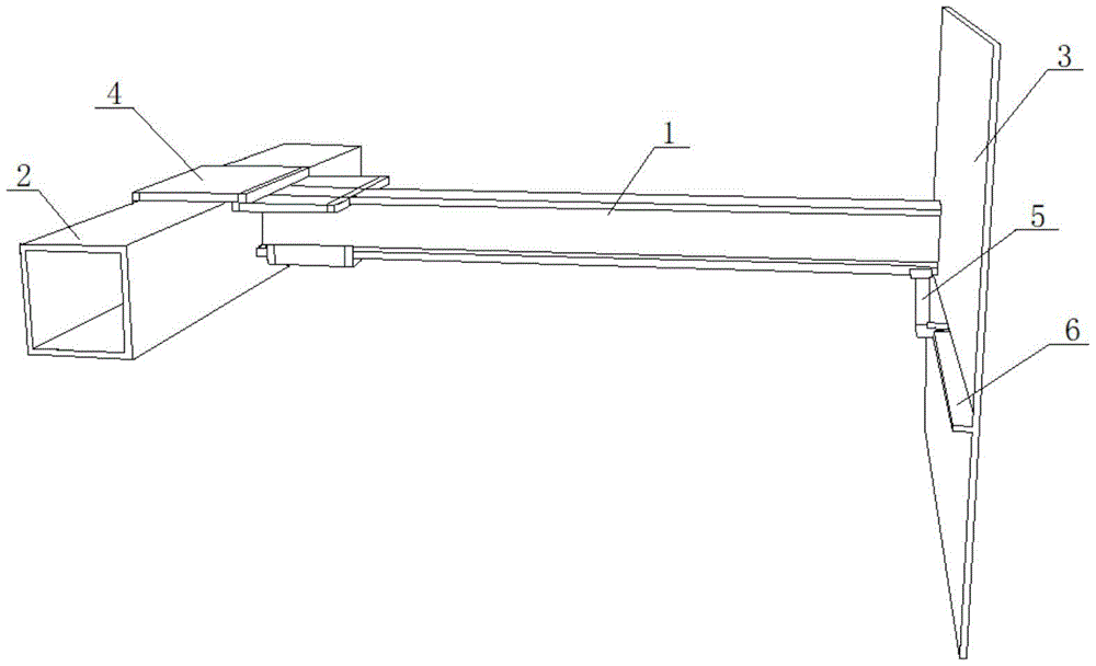
As shown in fig. 1, the present invention provides a workpiece mounting and fixing device, which comprises a first workpiece and a second workpiece to be connected with the first workpiece. In this embodiment, the two ends of the small beam are welded and fixed to the towing beam and the side beam, the first workpiece is the small beam 1 having a certain length, the second workpiece is the towing beam 2 and the side beam 3, and the two end surfaces of the small beam 1 are welded and fixed to the side surfaces of the towing beam 2 and the side beam 3.
The device also comprises two connecting elements, namely a first connecting element 4 and a second connecting element 5, because the number of the second workpieces connected with the first workpiece is two. The first connecting piece 4 is used for temporarily connecting the small cross beam 1 with the traction beam 2, the second connecting piece 5 is used for temporarily connecting the small cross beam 1 with the edge beam 3, and the connecting pieces need to be detached and taken down from the small cross beam 1, the traction beam 2 and the edge beam 3 after welding.
As shown in fig. 1 and 2, the first connecting member 4 has a first connecting portion 41 and a second connecting portion 42 connected to each other, the first connecting portion 41 is used for being connected to the small beam 1, the second connecting portion 42 is used for being connected to the draft sill 2, the first connecting portion 41 and the second connecting portion 42 are detachably connected to the small beam 1 and the draft sill 2, and the first connecting member 4 is conveniently mounted and dismounted from the draft sill 2 and the small beam 1 before and after welding.
In this embodiment, the first connecting portion 41 of the first connecting member 4 is in a lifting structure, and the small beam 1 is lifted and fixed above the lifting structure. The small cross beam 1 is fixed in a lifting mode, so that the operation is very simple and convenient, the freedom degree of the small cross beam 1 in the horizontal direction is favorably released, the relative position between the small cross beam 1 and the traction beam 2 is conveniently adjusted in real time, and the accuracy of the installation position is favorably ensured.
More preferably, the first connecting portion 41 is a U-shaped lifting slot that is open upward, the bottom of the small beam 1 is clamped in the U-shaped lifting slot, and the slot width of the U-shaped lifting slot is preferably matched with the width of the small beam 1. The small beam 1 is vertically welded on the side surface of the towing beam 2, so the upward slot edges on the two sides of the U-shaped lifting slot are vertical to the side surface of the towing beam 2, and the structure of the U-shaped lifting slot can effectively limit the freedom degree of the small beam 1 in the direction parallel to the side surface of the towing beam 2, thereby achieving the purpose of better controlling the installation size and being beneficial to ensuring the welding quality during welding.
The relative positions of the first connecting portion 41 and the second connecting portion 42 are designed according to the relative positions of two workpieces to be connected, in this embodiment, according to the installation positions of the small beam 1 and the draft sill 2, the highest connection point of the side surfaces of the small beam 1 and the draft sill 2 is lower than the upper surface of the draft sill 2, and the second connecting portion 42 of the first connecting member 4 is located on one side of the first connecting portion 41 and higher than the first connecting portion 41.
For convenience of disassembly and assembly, in this embodiment, it is preferable that the second connecting portion 42 is fastened to the towing beam 2 by a fastening structure. More preferably, the second connecting portion 42 is a C-shaped slot, and the C-shaped slot straddles from one side of the towing beam 2 connected with the small cross beam 1 to the other side away from the small cross beam 1 and is laterally fixed on the towing beam 2 in a clamping manner. When installing first connecting piece 4, can span the C-shaped draw-in groove and block on draw beam 2 from one side again on the upper surface of draw beam 2, place little crossbeam 1 on the groove is lifted to the U-shaped simultaneously, can realize being connected between first connecting piece 4 and little crossbeam 1 and draw beam 2. Of course, the C-shaped clamping groove may also be a structure with a downward opening, and the C-shaped clamping groove is bridged on the upper surface of the draft sill 2 and clamped and fixed downward from above the draft sill 2. The structure of the C-shaped clamping groove is equivalent to that the small beam 1 is hung on one side of the traction beam 2. The installation position of the small beam 1 can be accurately determined by accurately controlling the distance between the surface of the C-shaped clamping groove in contact with the traction beam 2 and the lifting surface of the U-shaped lifting groove for supporting the small beam 1.
In this embodiment, in order to further limit the degree of freedom of the minimum cross beam 1 in the vertical direction during the installation process, it is more preferable that a positioning portion 43 protruding toward the small cross beam 1 is provided at the top of the first connecting portion 41, and a positioning surface 44 is provided on the lower surface of the positioning portion 43, and the positioning surface 44 is in contact with the upper surface of the small cross beam 1 during the connection, that is, the small cross beam 1 is clamped between the positioning surface 44 and the lifting surface of the U-shaped lifting groove in the vertical direction. Because a certain height difference exists between the small cross beam 1 and the traction beam 2, a vertical connection part is also arranged between the positioning part 43 and the upper edge of the C-shaped clamping groove of the second connecting part 42.
As shown in fig. 1 and 3, the second connecting member 5 also has a first connecting portion 51 and a second connecting portion 52 connected to each other, the first connecting portion 51 is used for connecting with the small beam 1, the second connecting portion 52 is used for connecting with the edge beam 3, and the edge beam joist 6 on the side surface of the edge beam 3 is selected as a fixing and supporting point of the second connecting member 5 in the present embodiment because the main body of the edge beam 3 has no suitable fixing point.
The first connecting portion 51 and the second connecting portion 52 are detachably connected with the small cross beam 1 and the edge beam joist 6, and the second connecting portion 5 is conveniently mounted and dismounted from the edge beam joist 6 and the small cross beam 1 before and after welding.
The first connecting part 51 of the second connecting part 5 also adopts a lifting structure, and the small beam 1 is lifted and fixed above the lifting structure. The small cross beam 1 is fixed in a lifting mode, so that the operation is very simple and convenient, the freedom degree of the small cross beam 1 in the horizontal direction is favorably released, the relative position between the small cross beam 1 and the boundary beam 3 is conveniently adjusted in real time, and the accuracy of the installation position is favorably ensured.
More preferably, the first connecting portion 51 is a U-shaped lifting slot with an upward opening, the bottom of the end of the small beam 1 connected with the edge beam 3 is clamped in the U-shaped lifting slot, and the slot width of the U-shaped lifting slot is preferably matched with the width of the small beam 1. Because the small crossbeam 1 is welded on the side surface of the boundary beam 3 vertically, the upward slot edges at the two sides of the U-shaped lifting slot are perpendicular to the side surface of the boundary beam 3, and the structure of the U-shaped lifting slot can effectively limit the freedom degree of the small crossbeam 1 in the direction parallel to the side surface of the boundary beam 3, thereby achieving the purpose of better controlling the installation size and being beneficial to ensuring the welding quality during welding.
According to the mounting positions of the small cross beam 1 and the boundary beam supporting rib 6, the boundary beam supporting rib 6 is lower than the position of the side surface connecting point of the small cross beam 1 and the boundary beam 3, the second connecting part 52 of the second connecting piece 5 is positioned below the first connecting part 51 and extends out in the direction of the boundary beam supporting rib 6, and the second connecting piece 5 is integrally of an L-shaped structure.
In order to facilitate the disassembly and assembly, the second connecting portion 52 is also clamped, and more preferably, the second connecting portion 52 is a C-shaped clamping groove and is directly clamped into the edge beam supporting rib 6 from one side of the edge beam supporting rib 6 to be fixed. In order to ensure that the force application and the disassembly are convenient, a claw locking bolt 53 is arranged below the C-shaped clamping groove, and the second connecting piece 5 and the edge beam supporting rib 6 are firmly fixed by the locking bolt 53. Of course, the second connecting portion 52 may be fixed to the edge rail 6 by using a flange structure or the like.
In order to adjust the lifting height of the U-shaped lifting groove in the second connecting member 5 relative to the edge beam lifting rib 6, in this embodiment, it is preferable that an adjusting mechanism 7 is further connected between the first connecting portion 51 and the second connecting portion 52, and the adjusting mechanism 7 is used for adjusting the relative distance between the first connecting portion 51 and the second connecting portion 52, that is, the lifting height of the first connecting portion 51, so as to accurately determine the installation position of the small beam 1.
Preferably, the adjusting mechanism 7 comprises a first member 71 and a second member 72 which are sleeved with each other, and the first member 71 and the second member 72 are coaxially sleeved to form a sliding pair. More preferably, the first piece 71 and the second piece 72 are both of a cylindrical structure with a rectangular cross section, the second piece 72 is nested in the first piece 71, the first piece 71 is fixedly connected with the first connecting portion 51, the second piece 72 is fixedly connected with the second connecting portion 52, and the first piece 71 and the second piece 72 are fixed through a positioning structure. The positioning structure comprises a plurality of positioning holes 73 formed in the side surfaces of the first piece 71 and the second piece 72, the first piece 71 and the second piece 72 are relatively moved, and after the first piece 71 and the second piece 72 are adjusted in place, the first connecting portion 51 can be fixed in the lifting height relative to the second connecting portion 52 by inserting positioning pins (not shown in the figure) into the corresponding positioning holes, and the adjusting mechanism 7 is favorable for improving the speed of adjustment and disassembly. The adjusting mechanism 7 can also adopt a spiral ejector rod mechanism, a hydraulic lifting mechanism and other structures.
A guide structure 74 is further provided between the first member 71 and the second member 72 to ensure coaxiality when the first member 71 and the second member 72 are adjusted relative to each other, and the guide structure 74 is composed of a guide groove extending in the moving direction and a guide block (not shown) provided on each of the first member 71 and the second member 72, the guide block being slidably fitted in the guide groove.
Of course, for the first connecting member 4, a height-adjustable structure may also be adopted between the first connecting portion 41 and the second connecting portion 42, that is, the portion of the vertical connection between the positioning portion 43 and the upper edge of the C-shaped slot of the second connecting portion 42 may use the adjusting mechanism 7 as described above, so that the lifting height of the small cross beam 1 relative to the towing beam 2 may also be changed.
In this embodiment, preferably, the first connecting member 4 and the second connecting member 5 are made of stainless steel plates, so as to be in direct contact with aluminum alloy. The connecting piece is formed by bending a stainless steel plate and welding the stainless steel plate by argon arc welding, or the first connecting piece 4 and the second connecting piece 5 can be manufactured by integral casting or machining.
When carrying out assembly welding with little crossbeam 1 and draw beam 2 and boundary beam 3, earlier with first connecting piece 4 fixed mounting on the one end and the draw beam 2 of little crossbeam 1, first connecting piece 4 stretches over fixed little crossbeam 1 of lifting simultaneously on the upper surface of draw beam 2, earlier on the C shape draw-in groove of 5 bottoms of second connecting piece transversely insert boundary beam brace 6 again, it is fixed with locking bolt 53, adjust adjustment mechanism 7 simultaneously, it is fixed with adjusting position to utilize the locating pin after targetting in place to adjust, and then the height of lifting of fixed little crossbeam 1. After the connection, the two ends of the small cross beam 1 are closely attached to the side surfaces of the traction beam 2 and the boundary beam 3, and then tack welding is performed. And after the final construction operation is finished, the first connecting piece 4 and the second connecting piece 5 are detached from the small cross beam 1, the traction beam 2 and the boundary beam 3.
The device utilizes first connecting piece 4 and second connecting piece 5 to be in the same place the little crossbeam 1 that needs to be connected with draw beam 2 and boundary beam 3 temporary connection, utilizes draw beam 2 and boundary beam 3 fixed stay little crossbeam 1, not only is favorable to conveniently accurately positioning the mounted position of little crossbeam 1, has reduced the equipment time, is favorable to accurate control installation size moreover, is favorable to the standardization of production operation, has greatly promoted installation quality and efficiency.
The device has fully considered the operation of next process, utilize draw beam 2 and boundary beam 3 to provide the fixed stay point for the little crossbeam 1 that needs to connect, the shared space of connection structure has been reduced, sufficient construction space has been set aside for follow-up tack welding, make the welding reachability promote, difficult production welding defect, it is limited to have solved under the car construction space, the intensive problem of operation personnel, when reducing the potential safety hazard, working hour and cost have been practiced thrift greatly, the production efficiency is improved, and the product quality is promoted.
The device adopts a lifting structure to fix and support the connected small cross beam 1, adopts a clamping mode to fix the traction beam 2 and the boundary beam 3, is very concise and convenient to operate, and can be used for completing the installation and the disassembly of the device within several seconds. Meanwhile, the adoption of the lifting structure is also beneficial to releasing the degree of freedom of the small beam 1 in the horizontal direction, is convenient for adjusting the relative position between the small beam 1 and the traction beam 2 as well as the boundary beam 3 in real time, and is beneficial to ensuring the precision of the installation position.
The device is also suitable for the connection condition of other workpieces, and the required connecting piece structure is correspondingly selected according to the installation position of the connection point.
Although the present invention has been described with reference to the preferred embodiments, it will be understood by those skilled in the art that various changes may be made and equivalents may be substituted for elements thereof without departing from the scope of the present invention.