CN216959033U - High-efficient radiating protected switch cabinet - Google Patents
High-efficient radiating protected switch cabinet Download PDFInfo
- Publication number
- CN216959033U CN216959033U CN202123037577.4U CN202123037577U CN216959033U CN 216959033 U CN216959033 U CN 216959033U CN 202123037577 U CN202123037577 U CN 202123037577U CN 216959033 U CN216959033 U CN 216959033U
- Authority
- CN
- China
- Prior art keywords
- heat
- heat dissipation
- switch cabinet
- outlet
- inlet
- Prior art date
- Legal status (The legal status is an assumption and is not a legal conclusion. Google has not performed a legal analysis and makes no representation as to the accuracy of the status listed.)
- Expired - Fee Related
Links
Images



Landscapes
- Cooling Or The Like Of Electrical Apparatus (AREA)
Abstract
A protective switch cabinet with high-efficiency heat dissipation comprises a switch door, a heat absorption sheet, a switch cabinet, a heat absorption pipe, a first connecting pipe, a heat dissipation box, a heat dissipation motor, a heat dissipation fan connecting platform, a heat dissipation sheet, a water storage tank and a water pump, the switch cabinet front portion is connected with the switch door rotation, the heat absorption piece is connected to the switch cabinet left and right sides, heat absorption piece internal connection heat absorption pipe, the heat absorption piece rear portion has the heat absorption export, the heat absorption entry, the heat absorption export is located heat absorption entry upside, heat absorption pipe entry end and heat absorption entry linkage, heat absorption pipe exit end and heat absorption exit linkage, heat dissipation case right side has the heat dissipation entry, the heat dissipation export, the heat dissipation entry is located the heat dissipation export upside, a plurality of fin of the anterior fixed connection of heat dissipation case, the fin left and right sides has the heat dissipation connecting pipe, heat dissipation case left and right sides casing inside has the internal connection pipe, internal connection pipe and heat dissipation connecting pipe fixed connection.
Description
Technical Field
The utility model relates to the field of switch cabinets, in particular to a protective switch cabinet capable of efficiently dissipating heat.
Background
In the working process of the internal elements of the protective switch cabinet, heat can be generated, the use effect of the electronic elements can be influenced when the internal elements are in a high-temperature state or the temperature is too high for a long time, and the elements can be damaged even under extreme conditions.
SUMMERY OF THE UTILITY MODEL
Aiming at the defects in the prior art, the utility model provides the protective switch cabinet with high heat dissipation efficiency.
The purpose of the utility model is realized by the following technical scheme:
a protective switch cabinet capable of dissipating heat efficiently comprises a switch door, heat absorbing sheets, a switch cabinet, heat absorbing pipes, a first connecting pipe, a heat dissipating box, a heat dissipating motor, a heat dissipating fan connecting table, heat dissipating fins, a water storage tank and a water pump, wherein the front part of the switch cabinet is rotationally connected with the switch door, the left side and the right side of the switch cabinet are connected with the heat absorbing sheets, the heat absorbing sheets are internally connected with the heat absorbing pipes, the rear part of each heat absorbing sheet is provided with a heat absorbing outlet and a heat absorbing inlet, the heat absorbing outlet is positioned above the heat absorbing inlet, the inlet end of each heat absorbing pipe is connected with the heat absorbing inlet, the outlet end of each heat absorbing pipe is connected with the heat absorbing outlet, the right side of the heat dissipating box is provided with a heat dissipating inlet and a heat dissipating outlet, the heat dissipating inlets are positioned above the heat dissipating outlets, the front part of the heat dissipating box is fixedly connected with a plurality of heat dissipating fins, the left side and the right side of the heat dissipating fins are provided with heat dissipating connecting pipes, the inner connecting pipes are arranged in the shells on the left side and right side of the heat dissipating box, the heat dissipation device comprises an internal connecting pipe, a heat dissipation loop inlet, a heat dissipation loop outlet, a heat dissipation outlet, a motor placing table, a heat dissipation motor, a heat dissipation fan connecting table, a heat dissipation fan blade, a water tank connecting port, a heat dissipation outlet, a water pump, a heat absorption inlet, a first connecting pipe, a heat dissipation inlet, a heat dissipation connecting pipe, a heat dissipation fin, an internal connecting pipe, a heat dissipation outlet, a water tank connecting port, a water pump, a second connecting pipe, a heat dissipation inlet, a heat dissipation outlet, a heat absorption fan, a heat dissipation fan blade, a water tank connecting port, a heat absorption fan connecting table, a heat dissipation fan blade, a water tank connecting pipe, a heat dissipation fan blade, a heat dissipation fan, a heat pipe, a heat absorption outlet, a heat absorption pipe, a heat absorption pipe, a heat absorption pipe, a heat sink, a heat pipe, a heat sink, a, The heat absorption inlets are communicated to form a heat dissipation loop.
The left side and the right side of the switch cabinet are provided with clamping grooves, the bottom of the heat absorbing sheet top is provided with clamping bosses, the clamping bosses are matched with the clamping grooves, the clamping bosses are connected with the clamping grooves, and the clamping bosses are clamped in the clamping grooves.
Has the advantages that:
the heat absorbing sheet is connected with the clamping groove of the switch cabinet through the clamping boss, the replacement and maintenance of the heat absorbing sheet are convenient, when the switch cabinet needs to be radiated, the water pump and the heat radiating motor are started to drive the cooling liquid in the water storage tank to flow in the heat radiating loop, when the cooling liquid flows into the heat absorbing pipe, the cooling liquid can absorb the heat emitted by the switch cabinet, when the cooling liquid absorbing heat flows into the heat radiating fin, the heat radiating motor drives the heat radiating fan connecting platform to rotate to accelerate the air flow at the position of the heat radiating fin, so that the cooling liquid flowing inside the heat radiating fin can be quickly cooled, the heat radiating fin is a rectangular thin sheet with a space inside, the heat radiating surface area of the cooling liquid flowing into the heat radiating fin is increased, the heat radiating efficiency is further improved, the cooled cooling liquid can absorb the heat emitted by the switch cabinet again after entering the heat absorbing pipe again, one-time cooling circulation is completed, and the overall structure is reasonable, the cooling efficiency is high.
Drawings
Fig. 1 is a front view of a high-efficiency heat-dissipating protective switch cabinet according to the present invention.
Fig. 2 is a front partial sectional view of a protective switch cabinet with high heat dissipation efficiency according to the present invention.
Fig. 3 is a side view of a protective switch cabinet with efficient heat dissipation according to the present invention.
Fig. 4 is a side view of the cooling device of the present invention.
Fig. 5 is a front view of the cooling device of the present invention.
Fig. 6 is a schematic structural view of a protective switch cabinet with high heat dissipation efficiency according to the present invention.
Detailed Description
The utility model is explained in more detail below with reference to the figures and examples:
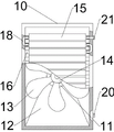
a high-efficiency heat-dissipation protective switch cabinet comprises a switch door 1, heat absorbing sheets 2, a switch cabinet 3, heat absorbing pipes 6, a first connecting pipe 7, a heat dissipation box 10, a heat dissipation motor 11, a heat dissipation fan connecting table 14, heat dissipation fins 15, a water storage tank 17 and a water pump 19, wherein the front part of the switch cabinet 3 is rotatably connected with the switch door 1, the left side and the right side of the switch cabinet 3 are connected with the heat absorbing sheets 2, the heat absorbing sheets 2 are internally connected with the heat absorbing pipes 6, the rear part of each heat absorbing sheet 2 is provided with a heat absorbing outlet 8 and a heat absorbing inlet 9, the heat absorbing outlet 8 is positioned on the upper side of the heat absorbing inlet 9, the inlet end of each heat absorbing pipe 6 is connected with the heat absorbing inlet 9, the outlet end of each heat absorbing pipe 6 is connected with the heat absorbing outlet 8, the right side of the heat dissipation box 10 is provided with a heat dissipation inlet 21 and a heat dissipation outlet 20, the heat dissipation inlet 21 is positioned on the upper side of the heat dissipation outlet 20, the front part of the heat dissipation box 10 is fixedly connected with a plurality of heat dissipation fins 15, the left side and the heat dissipation fins 15 are provided with heat dissipation connecting pipes 16, the inside of the shell on the left side and the right side of the heat dissipation box 10 is provided with an internal connecting pipe 18, the internal connecting pipe 18 is fixedly connected with a heat dissipation connecting pipe 16, the internal connecting pipe 18 and a water pump 19 connector form a heat dissipation loop, the inlet of the heat dissipation loop is connected with a heat dissipation inlet 21, the outlet of the heat dissipation loop is connected with a heat dissipation outlet 20, the bottom of the heat dissipation box 10 is provided with a motor placing table 12, the motor placing table 12 is positioned on the rear side of a heat dissipation fin 15, the top of the motor placing table 12 is fixedly connected with a heat dissipation motor 11, the front part of the heat dissipation motor 11 is fixedly connected with a heat dissipation fan connecting table 14, the periphery of the heat dissipation fan connecting table 14 is provided with a heat dissipation fan blade 13, the right side of a water storage tank 17 is provided with a water tank connecting port 23, the water tank connecting port 23 is fixedly connected with the heat dissipation outlet 20, the left side of the water storage tank 17 is fixedly connected with a water pump 19, the left side of the water pump 19 is connected with a heat absorption inlet 9 by a second connecting pipe 22, and the heat dissipation inlet 21 is connected with a heat absorption outlet 8 by a first connecting pipe 7, the heat absorption pipe 6, the heat absorption outlet 8, the first connecting pipe 7, the heat dissipation inlet 21, the heat dissipation connecting pipe 16, the heat dissipation fin 15, the internal connecting pipe 18, the heat dissipation outlet 20, the water tank connecting port 23, the water storage tank 17, the water pump 19, the second connecting pipe 22 and the heat absorption inlet 9 are communicated to form a heat dissipation loop.
The left side and the right side of the switch cabinet 3 are provided with clamping grooves 5, the top bottom of the heat absorbing sheet 2 is provided with a clamping boss 4, the clamping boss 4 is matched with the clamping grooves 5, the clamping boss 4 is connected with the clamping grooves 5, and the clamping boss 4 is clamped in the clamping grooves 5.
The heat absorbing sheet 2 is connected with a clamping groove 5 arranged on the switch cabinet 3 through a clamping boss 4, so that the replacement and maintenance of the heat absorbing sheet 2 are convenient, when the switch cabinet 3 needs to be radiated, a water pump 19 and a heat radiating motor 11 are started to drive cooling liquid in a water storage tank 17 to flow in a heat radiating loop, when the cooling liquid flows into a heat absorbing pipe 6, the cooling liquid can absorb heat emitted by the switch cabinet 3, when the cooling liquid absorbing heat flows into a radiating fin 15, the heat radiating motor 11 drives a radiating fan connecting table 14 to rotate to accelerate the air flow at the position of the radiating fin 15, so that the cooling liquid flowing inside the radiating fin 15 can be rapidly cooled, the radiating fin 15 is a rectangular sheet with a space inside, the heat radiating surface area of the cooling liquid flowing into the radiating fin 15 is increased, the heat radiating efficiency is further improved, and the cooled cooling liquid can absorb the heat emitted by the switch cabinet 3 again after entering the heat absorbing pipe 6 again, the cooling circulation is completed once, the overall structure is reasonable, and the cooling efficiency is high.
Claims (4)
1. A protective switch cabinet capable of dissipating heat efficiently is characterized by comprising a switch door, heat absorbing sheets, a switch cabinet, heat absorbing pipes, a first connecting pipe, a heat dissipating box, a heat dissipating motor, a heat dissipating fan connecting platform, heat dissipating fins, a water storage tank and a water pump, wherein the front part of the switch cabinet is rotationally connected with the switch door, the left side and the right side of the switch cabinet are connected with the heat absorbing sheets, the heat absorbing sheets are internally connected with the heat absorbing pipes, the rear part of each heat absorbing sheet is provided with a heat absorbing outlet and a heat absorbing inlet, the heat absorbing outlet is positioned above the heat absorbing inlet, the inlet end of each heat absorbing pipe is connected with the heat absorbing inlet, the outlet end of each heat absorbing pipe is connected with the heat absorbing outlet, the right side of the heat dissipating box is provided with the heat dissipating inlet and the heat dissipating outlet, the heat dissipating inlets are positioned above the heat dissipating outlets, the front part of the heat dissipating box is fixedly connected with a plurality of heat dissipating fins, the left side and the right side of the heat dissipating fins are provided with heat dissipating connecting pipes, the inner connecting pipes are arranged inside of the shells on the left side and right side of the heat dissipating box, the internal connecting pipe and the water pump connector form a heat dissipation loop, the inlet of the heat dissipation loop is connected with the heat dissipation inlet, and the outlet of the heat dissipation loop is connected with the heat dissipation outlet.
2. The protective switch cabinet with high heat dissipation efficiency as claimed in claim 1, wherein the bottom of the heat dissipation box is provided with a motor placing table, the motor placing table is located at the rear side of the heat dissipation plate, the top of the motor placing table is fixedly connected with a heat dissipation motor, the front of the heat dissipation motor is fixedly connected with a heat dissipation fan connecting table, the periphery of the heat dissipation fan connecting table is provided with heat dissipation fan blades, the right side of the water storage tank is provided with a water tank connecting port, the water tank connecting port is fixedly connected with a heat dissipation outlet, and the left side of the water storage tank is fixedly connected with a water pump.
3. The high-efficiency heat-dissipation protective switch cabinet as claimed in claim 2, wherein the left side of the water pump is connected with the heat absorption inlet through a second connecting pipe, the heat dissipation inlet is connected with the heat absorption outlet through a first connecting pipe, and the heat absorption pipe, the heat absorption outlet, the first connecting pipe, the heat dissipation inlet, the heat dissipation connecting pipe, the heat dissipation fins, the internal connecting pipe, the heat dissipation outlet, the water tank connecting port, the water storage tank, the water pump, the second connecting pipe and the heat absorption inlet are communicated to form a heat dissipation loop.
4. The protective switch cabinet with the efficient heat dissipation function as claimed in claim 3, wherein the switch cabinet is provided with clamping grooves on the left side and the right side, the top and the bottom of the heat absorbing sheet are provided with clamping bosses, the clamping bosses are matched with the clamping grooves, the clamping bosses are connected with the clamping grooves, and the clamping bosses are clamped in the clamping grooves.
Priority Applications (1)
| Application Number | Priority Date | Filing Date | Title |
|---|---|---|---|
| CN202123037577.4U CN216959033U (en) | 2021-12-06 | 2021-12-06 | High-efficient radiating protected switch cabinet |
Applications Claiming Priority (1)
| Application Number | Priority Date | Filing Date | Title |
|---|---|---|---|
| CN202123037577.4U CN216959033U (en) | 2021-12-06 | 2021-12-06 | High-efficient radiating protected switch cabinet |
Publications (1)
| Publication Number | Publication Date |
|---|---|
| CN216959033U true CN216959033U (en) | 2022-07-12 |
Family
ID=82307047
Family Applications (1)
| Application Number | Title | Priority Date | Filing Date |
|---|---|---|---|
| CN202123037577.4U Expired - Fee Related CN216959033U (en) | 2021-12-06 | 2021-12-06 | High-efficient radiating protected switch cabinet |
Country Status (1)
| Country | Link |
|---|---|
| CN (1) | CN216959033U (en) |
-
2021
- 2021-12-06 CN CN202123037577.4U patent/CN216959033U/en not_active Expired - Fee Related
Similar Documents
| Publication | Publication Date | Title |
|---|---|---|
| CN117977060B (en) | High-efficient heat abstractor of new energy automobile battery | |
| CN221947585U (en) | A green laser with external stabilization structure | |
| CN220774981U (en) | Heat abstractor for laser module | |
| CN112737195B (en) | Cooling device of motor | |
| CN213241066U (en) | Heat dissipation device of intelligent terminal | |
| CN222126691U (en) | A battery cooling device for energy storage | |
| CN211557619U (en) | Waterproof good heat dissipation's circuit board | |
| CN221228102U (en) | Heat radiation structure for closed circulating water cooling system | |
| CN220509379U (en) | A kind of cooling computer case | |
| CN215768997U (en) | A heat dissipation protection device for novel laser radar | |
| CN216804892U (en) | Overheating protection heat dissipation device of plastic printing machine | |
| CN210895318U (en) | High-efficient heat radiation structure for radiator | |
| CN213635609U (en) | Spliced transformer radiator | |
| CN212027924U (en) | High-efficient heat sink of diesel generating set | |
| CN211293887U (en) | Heat radiation structure for computer | |
| CN110764595A (en) | Heat radiator for notebook computer | |
| CN210804283U (en) | Heat radiator for notebook computer | |
| CN223639563U (en) | A variable frequency power cabinet heat dissipation device | |
| CN223896370U (en) | Overheat protection device for refrigeration equipment | |
| CN220691836U (en) | Water-cooling variable frequency transformer | |
| CN221427498U (en) | Oil immersed transformer shell | |
| CN222514719U (en) | Cooling and radiating structure of server chip | |
| CN222339851U (en) | A high heat dissipation LED switching power supply | |
| CN220795788U (en) | Computer motherboard with cooling function | |
| CN223493805U (en) | Cooling device of vertical rotary table injection molding machine |
Legal Events
| Date | Code | Title | Description |
|---|---|---|---|
| GR01 | Patent grant | ||
| GR01 | Patent grant | ||
| CF01 | Termination of patent right due to non-payment of annual fee |
Granted publication date: 20220712 |
|
| CF01 | Termination of patent right due to non-payment of annual fee |