CN216957961U - Double-side detection equipment - Google Patents
Double-side detection equipment Download PDFInfo
- Publication number
- CN216957961U CN216957961U CN202123118281.5U CN202123118281U CN216957961U CN 216957961 U CN216957961 U CN 216957961U CN 202123118281 U CN202123118281 U CN 202123118281U CN 216957961 U CN216957961 U CN 216957961U
- Authority
- CN
- China
- Prior art keywords
- double
- axis
- detection
- axis driving
- driving device
- Prior art date
- Legal status (The legal status is an assumption and is not a legal conclusion. Google has not performed a legal analysis and makes no representation as to the accuracy of the status listed.)
- Active
Links
Images




Landscapes
- Sampling And Sample Adjustment (AREA)
Abstract
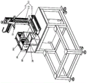
The utility model discloses double-side detection equipment which comprises a material taking and placing mechanism, material tray middle transposition, a double-station transplanting mechanism, a double-side detection station, a front-side AOI detection module positioned above the double-side detection station and a back-side AOI detection module positioned below the double-side detection station, wherein the material taking and placing mechanism is arranged on a material tray middle transposition part; the material taking and placing mechanism moves back and forth between the material loading position and the material tray for transposition, and the double-station transplanting mechanism passes through the material tray for transposition and the double-side detection station. The double-side wafer is taken and placed by adopting the double-station transplanting mechanism in detection, so that the time interval of twice detection feeding is shortened, the detection efficiency of the product is improved, and the double-side detecting mechanism is matched with the detection of the double-side detecting station to detect the front side and the back side at one time, so that the detection efficiency of the product is further improved.
Description
Technical Field
The utility model relates to the technical field of equipment, in particular to double-sided detection equipment which is mainly applied to detection of double-sided wafers.
Background
In the production process of two-sided wafer, the yields is very important condition, and is very strict to the quality requirement of two-sided wafer, when mass production, often need carry out outward appearance to two-sided wafer and detect, for example: size, breakage, porosity, crack defects, and the like.
At present, appearance detection is usually carried out manually by manpower, and the manpower is time-consuming and labor-consuming, so that the quality of double-sided wafers cannot be ensured during mass production due to the adoption of a spot inspection method in most cases; later, the existing wafer detection equipment can only detect a single surface, so that the two surfaces of the wafer need to be detected in a positive and negative way respectively, and the detection working efficiency is difficult to further improve. Moreover, the two detections also need multiple positioning, which affects the detection precision and quality.
Therefore, it is necessary to design a new wafer inspection apparatus to solve the above problems.
SUMMERY OF THE UTILITY MODEL
In view of the above, the present invention provides a double-sided detection apparatus, which uses a double-station transplanting mechanism to pick and place a detection product during detection of a double-sided wafer, so as to shorten a time interval between two detection feeding, improve the detection efficiency of the product, and detect the front and back sides at one time in cooperation with the detection of the double-sided detection station, thereby further improving the detection efficiency of the product.
In order to achieve the purpose, the utility model adopts the following technical scheme:
a double-side detection device comprises a material taking and placing mechanism, material tray transposition, a double-station transplanting mechanism, a double-side detection station, a front-side AOI detection module positioned above the double-side detection station and a back-side AOI detection module positioned below the double-side detection station; wherein:
the material taking and placing mechanism moves back and forth between the material loading position and the material tray for transposition, and the double-station transplanting mechanism passes through the material tray for transposition and the double-side detection station.
As a preferred scheme, the material loading device further comprises a bin lifting basket, wherein the bin lifting basket is arranged at a material loading position, and the material loading position is arranged beside the material tray in a transposition manner; the bin lifting basket is provided with a plurality of material tray grooves which are arranged in parallel at intervals; the material taking and placing mechanism is arranged beside the side where the material tray is rotated, the material taking and placing mechanism comprises an XYZ-axis moving device and a material taking and placing device C arranged on the XYZ-axis moving device, and the XYZ-axis moving device drives the material taking and placing device C to move on an XYZ axis.
Preferably, the XYZ-axis movement apparatus includes a first X-axis driving apparatus, a first Z-axis driving apparatus disposed on the first X-axis driving apparatus, and a first Y-axis driving apparatus disposed on the first Z-axis driving apparatus, and the pick-and-place apparatus C is disposed on the first Y-axis driving apparatus.
Preferably, the bin baskets are arranged side by side.
As a preferred scheme, the device further comprises an XY theta three-axis platform, wherein the XY theta three-axis platform comprises a second X-axis driving device, a second Y-axis driving device arranged on the second X-axis driving device, and a detection table arranged on the second Y-axis driving device, the double-sided detection station is arranged on the detection table, the second X-axis driving device drives the double-sided detection station to move on the X axis, the second Y-axis driving device drives the double-sided detection station to move on the Y axis, the detection table is further provided with a theta-axis driving device for driving the double-sided detection station to rotate, and the back AOI detection module sequentially penetrates through the second X-axis driving device, the second Y-axis driving device and the detection table and faces the double-sided detection station.
As a preferred scheme, the front AOI detection module and the back AOI detection module both have a second Z-axis driving device for driving the detection camera to focus.
As a preferred scheme, a positioning jig is arranged on the detection table corresponding to the double-side detection station.
As a preferred scheme, the double-station transplanting mechanism comprises a third X-axis driving device, two third Y-axis driving devices arranged on the third X-axis driving device, and a taking and placing device a and a taking and placing device B respectively arranged on the two third Y-axis driving devices; the third X-axis driving device drives the taking and placing device A and the taking and placing device B to move on the X axis, and the two third Y-axis driving devices respectively drive the taking and placing device A and the taking and placing device B to move on the Y axis.
Preferably, a flat plate is arranged on the third X-axis driving device, and the two third Y-axis driving devices are arranged on the flat plate at intervals along the X-axis.
Compared with the prior art, the utility model has obvious advantages and beneficial effects, and specifically, the technical scheme includes that:
the double-side wafer detection device mainly comprises a double-station transplanting mechanism, a double-station transplanting mechanism and a double-station transplanting mechanism, wherein the double-station transplanting mechanism is used for taking and placing detection products in the detection process, so that the time interval of twice detection and feeding is shortened, the detection efficiency of the products is improved, and the detection of the double-side detecting station is matched to detect the front side and the back side at one time, so that the detection efficiency of the products is further improved;
secondly, the material is loaded through the bin lifting basket, so that the material is conveniently loaded on the material tray; and two bin baskets are arranged, so that the continuity of the equipment is improved, and the non-stop feeding is realized.
To more clearly illustrate the structural features and effects of the present invention, the present invention will be described in detail below with reference to the accompanying drawings and specific embodiments.
Drawings
FIG. 1 is an assembled perspective view of the preferred embodiment of the present invention;
FIG. 2 is a perspective view of a preferred embodiment of the present invention (without the housing);
FIG. 3 is a perspective view of another perspective of the preferred embodiment of the present invention (without the housing);
FIG. 4 is a top view of the preferred embodiment of the present invention (without the housing);
FIG. 5 is a first partial assembly view (indexing in the pick and place mechanism, bin basket, tray) of the preferred embodiment of the present invention;
FIG. 6 is a second partial assembly view of the preferred embodiment of the present invention (dual-station transplanting mechanism, front AOI inspecting module, back AOI inspecting module, XY θ three-axis platform, dual-side inspecting station);
FIG. 7 is a second partial assembly view of the preferred embodiment of the present invention (front AOI inspection module, back AOI inspection module, XY θ three-axis stage, dual-side inspection station);
FIG. 8 is a schematic diagram of the detection process according to the preferred embodiment of the present invention;
FIG. 9 is a schematic view of a two-station transplanting mechanism (pneumatic jaws) according to a preferred embodiment of the present invention;
fig. 10 is a schematic view of a double-station transplanting mechanism (ring-shaped clamping claw) according to a preferred embodiment of the present invention.
The attached drawings indicate the following:
10. get drop feed mechanism 11, XYZ axle mobile device
111. First X-axis driving device 112 and first Z-axis driving device
113. First Y-axis driving device 12 and taking and placing device C
20. 30-station transplanting mechanism for indexing in tray
31. Pick-and-place device A32 and pick-and-place device B
33. Third X-axis drive 331, flat plate
34. Third Y-axis driving device 35 and clamping column
40. Double-side detection station 41 and tooth part
42. Positioning jig 50 and bin lifting basket
501. Tray groove 60 and front AOI detection module
61. Second Z-axis driving device 70 and back AOI detection module
80. Material loading position 90, shell
91. FFU blower 92 and visual window
93. 100, XY theta triaxial platform of can opening and shutting door
1001. Second X-axis driving device 1002 and second Y-axis driving device
1003. Test table 1004 and theta axis driving device
1005. Rotating electric machine 1006, gear
110. Marble base 1101, damping device.
Detailed Description
Referring to fig. 1 to 10, a specific structure of a preferred embodiment of the present invention is shown, which includes a double-sided detection method, including the following steps:
the first step is as follows: after the feeding and discharging mechanism 10 places a product to be detected into the tray and indexes 20, the taking and placing device A31 in the double-station transplanting mechanism 30 moves into the tray and indexes 20 to capture the product to be detected, at the moment, the taking and placing device B32 in the double-station transplanting mechanism 30 is in an idle state, wherein the taking and placing device A31 and the taking and placing device B32 are sequentially arranged;
the second step is that: the pick-and-place device A31 puts a product to be detected to the double-side detection station 40 for detection, and at the moment, the pick-and-place device A31 and the pick-and-place device B32 are both in an idle state;
the third step: before the pick-and-place device B32 moves to the tray middle position 20 to grab the next product to be detected, the pick-and-place mechanism 10 places the product to be detected into the tray middle position 20; then, after the pick-and-place device B32 moves to the tray and the indexing position 20 grabs the product to be detected, the pick-and-place device a31 and the pick-and-place device B32 both move to the waiting area;
the fourth step: the picking and placing device A31 picks the detected products, the picking and placing device B32 places the products to be detected to the double-sided detection station 40 for detection, and at the moment, the picking and placing device B32 is in an idle state;
the fifth step: before the pick-and-place device B32 moves to the tray and before the index 20 picks the next product to be detected, after the pick-and-place mechanism 10 puts the product to be detected into the tray and indexes 20, the pick-and-place device B32 indexes 20 in the tray to pick the product to be detected; then, the pick-and-place device a31 places the detected products into the tray and shifts 20, the pick-and-place mechanism 10 discharges the detected products, the pick-and-place device a31 and the pick-and-place device B32 both move to the waiting area, and at this time, the pick-and-place device a31 is in an idle state;
and a sixth step: and repeating the fourth step and the fifth step.
Specifically, the bin basket 50 containing the product to be tested is placed to an upper level 80 prior to the first step; the material taking and placing mechanism 10 grabs a product to be detected from the bin lifting basket 50;
in the fifth step, the picking and placing mechanism 10 puts the detected product into the bin lifting basket 50;
in the sixth step, the operation is stopped until all the products to be detected in the bin basket 50 are detected, and then the bin basket 50 is taken down to complete the detection of a batch of products.
Preferably, the number of the bin baskets 50 is two, and in the sixth step, until the products to be detected in the first bin basket 50 are all detected, the picking and placing mechanism 10 picks the products to be detected from the second bin basket 50, so as to realize continuous feeding, and after the first bin basket 50 with the products detected is picked, the bin basket 50 containing the products to be detected is placed again.
A double-sided detection device comprises a material taking and placing mechanism 10, a material tray middle transposition 20, a double-station transplanting mechanism 30, a double-sided detection station 40, a front-side AOI detection module 60 positioned above the double-sided detection station 40 and a back-side AOI detection module 70 positioned below the double-sided detection station 40; wherein:
the material taking and placing mechanism 10 moves back and forth between the material loading position 80 and the material tray middle indexing position 20, and the double-station transplanting mechanism 30 passes through the material tray middle indexing position 20 and the double-side detection position 40.
The two-sided check out test set dustcoat is equipped with shell 90, the top of shell 90 is provided with FFU fan 91, the left and right both sides of shell 90 are provided with the visual window 92 that is used for the operation of observation device, shell 90 corresponds the material loading position and is provided with the door 93 that can open and shut that is used for the material loading.
The material loading device further comprises a bin lifting basket 50, wherein the bin lifting basket 50 is arranged at a material loading position 80, and the material loading position 80 is arranged beside the transposition 20 in the material tray; the bin basket 50 has a plurality of tray slots 501 arranged in parallel at intervals; the taking and placing mechanism 10 is arranged beside the indexing position 20 in the tray, the taking and placing mechanism 10 comprises an XYZ-axis moving device 11 and a taking and placing device C12 arranged on the XYZ-axis moving device 11, and the XYZ-axis moving device 11 drives the taking and placing device C12 to move on XYZ axes;
the XYZ shaft transfer device 11 includes a first X shaft driving device 111, a first Z shaft driving device 112 disposed on the first X shaft driving device 111, and a first Y shaft driving device 113 disposed on the first Z shaft driving device 112, wherein the pick-and-place device C12 is disposed on the first Y shaft driving device 113;
preferably, the bin baskets 50 are arranged side by side, one bin basket 50 is arranged close to the middle indexing part 20 of the material tray, and the material taking and placing mechanism 10 takes materials from the bin basket 50 which is arranged far away from the middle indexing part 20 of the material tray.
The double-station transplanting mechanism 30 comprises a third X-axis driving device 33, two third Y-axis driving devices 34 arranged on the third X-axis driving device 33, a taking and placing device A31 and a taking and placing device B32 respectively arranged on the two third Y-axis driving devices 34; the third X-axis driving device 33 drives the pick-and-place device a31 and the pick-and-place device B32 to move on the X axis, and the two third Y-axis driving devices 34 respectively drive the pick-and-place device a31 and the pick-and-place device B32 to move on the Y axis;
a flat plate 331 is arranged on the third X-axis driving device 33, and two third Y-axis driving devices 34 are arranged on the flat plate 331 at intervals along the X-axis; the third X-axis driving device 33 drives the two third Y-axis driving devices 34 to move together.
The double-side detection device comprises a XY theta three-axis platform 100, wherein the XY theta three-axis platform 100 comprises a second X-axis driving device 1001, a second Y-axis driving device 1002 arranged on the second X-axis driving device 1001, and a detection table 1003 arranged on the second Y-axis driving device 1002, the double-side detection station 40 is arranged on the detection table 1003, the second X-axis driving device 1001 drives the double-side detection station 40 to move on the X axis, the second Y-axis driving device 1002 drives the double-side detection station 40 to move on the Y axis, the detection table 1003 is further provided with a theta-axis driving device 1004 for driving the double-side detection station 40 to rotate, and the back AOI detection module 70 sequentially passes through the second X-axis driving device 1001, the second Y-axis driving device 1002 and the detection table 1003 and faces the double-side detection station 40;
the theta axis driving device 1004 comprises a rotary motor 1005 and a gear 1006 connected with the rotary motor 1005, correspondingly, the peripheral side of the double-sided detection station 40 is provided with a tooth part 41 meshed with the gear 1006, and the double-sided detection station 40 is rotated by the rotation of the gear 1006; the front AOI detection module 60 and the back AOI detection module 70 both have a second Z-axis driving device 61 for driving the detection camera to focus.
In addition, a positioning jig 42 is arranged on the detection table 1003 corresponding to the double-sided detection station 40, and the positioning jig 42 can be replaced according to the size of a product to be detected;
preferably, the double-station transplanting mechanism 30, the XY θ triaxial platform 100, the double-side detection station 40, the front-side AOI detection module 60 and the back-side AOI detection module 70 are all disposed on a marble base 110, and the four corners of the bottom of the marble base 110 are all provided with damping devices 1101.
As shown in fig. 9, the pick-and-place device a31 and the pick-and-place device B32 are both pneumatic clamping jaws clamped up and down; as shown in fig. 10, the pick-and-place device a31 and the pick-and-place device B32 are both annular clamping claws designed according to the size of the product to be measured, the annular clamping claws have four clamping columns 35, the four clamping columns 35 are two pairs arranged in front and back and are located on the same circle when clamping, and the two pairs of clamping columns 35 clamp the product in front and back.
The design of the utility model is characterized in that:
compared with the prior art, the utility model has obvious advantages and beneficial effects, and specifically, the technical scheme includes that:
the double-side wafer detection device mainly comprises a double-station transplanting mechanism, a double-station transplanting mechanism and a double-station transplanting mechanism, wherein the time interval of twice detection and feeding is shortened, the detection efficiency of products is improved, and the double-station transplanting mechanism is matched with the detection of double-side detection stations to detect the front side and the back side at one time, so that the detection efficiency of the products is further improved;
secondly, the material is loaded through the bin lifting basket, so that the material is conveniently loaded on the material tray; and two bin baskets are arranged, so that the continuity of the equipment is improved, and the non-stop feeding is realized.
The above description is only a preferred embodiment of the present invention, and is not intended to limit the technical scope of the present invention, so that any minor modifications, equivalent changes and modifications made to the above embodiment according to the technical spirit of the present invention are within the technical scope of the present invention.
Claims (9)
1. A kind of two-sided checkout equipment, characterized by: the automatic material taking and placing device comprises a material taking and placing mechanism, material tray middle transposition, a double-station transplanting mechanism, a double-side detection station, a front-side AOI detection module positioned above the double-side detection station and a back-side AOI detection module positioned below the double-side detection station; wherein:
the material taking and placing mechanism moves back and forth between the material loading position and the material tray for transposition, and the double-station transplanting mechanism passes through the material tray for transposition and the double-side detection station.
2. The double-sided detection apparatus of claim 1, wherein: the automatic feeding device is characterized by also comprising a storage bin lifting basket, wherein the storage bin lifting basket is arranged at a feeding position, and the feeding position is arranged beside the indexing position in the material tray; the bin lifting basket is provided with a plurality of material tray grooves which are arranged in parallel at intervals; the material taking and placing mechanism is arranged beside the side where the material tray is rotated, the material taking and placing mechanism comprises an XYZ-axis moving device and a material taking and placing device C arranged on the XYZ-axis moving device, and the XYZ-axis moving device drives the material taking and placing device C to move on an XYZ axis.
3. The double-sided detection apparatus of claim 2, wherein: the XYZ-axis moving device comprises a first X-axis driving device, a first Z-axis driving device arranged on the first X-axis driving device, and a first Y-axis driving device arranged on the first Z-axis driving device, and the taking and placing device C is arranged on the first Y-axis driving device.
4. The double-sided detection apparatus of claim 2, wherein: the bin lifting baskets are arranged side by side.
5. The double-sided detection apparatus of claim 1, wherein: the X-axis and Y-axis detection device comprises an X-axis and Y-axis platform, and is characterized by further comprising an XY-theta three-axis platform, wherein the XY-theta three-axis platform comprises a second X-axis driving device, a second Y-axis driving device arranged on the second X-axis driving device, and a detection table arranged on the second Y-axis driving device, the double-sided detection station is arranged on the detection table, the second X-axis driving device drives the double-sided detection station to move on the X axis, the second Y-axis driving device drives the double-sided detection station to move on the Y axis, the detection table is further provided with a theta-axis driving device for driving the double-sided detection station to rotate, and the back AOI detection module sequentially passes through the second X-axis driving device, the second Y-axis driving device and the detection table and faces the double-sided detection station.
6. The double-sided detection apparatus of claim 5, wherein: and the front AOI detection module and the back AOI detection module are both provided with a second Z-axis driving device for driving the detection camera to focus.
7. The double-sided detection apparatus of claim 6, wherein: a positioning jig is arranged on the detection table corresponding to the double-sided detection station.
8. The double-sided detection apparatus of claim 1, wherein: the double-station transplanting mechanism comprises a third X-axis driving device, two third Y-axis driving devices arranged on the third X-axis driving device, a taking and placing device A and a taking and placing device B which are respectively arranged on the two third Y-axis driving devices; the third X-axis driving device drives the taking and placing device A and the taking and placing device B to move on the X axis, and the two third Y-axis driving devices respectively drive the taking and placing device A and the taking and placing device B to move on the Y axis.
9. The double-sided detection apparatus of claim 8, wherein: and the third X-axis driving device is provided with a flat plate, and the two third Y-axis driving devices are arranged on the flat plate at intervals along the X axis.
Priority Applications (1)
| Application Number | Priority Date | Filing Date | Title |
|---|---|---|---|
| CN202123118281.5U CN216957961U (en) | 2021-12-13 | 2021-12-13 | Double-side detection equipment |
Applications Claiming Priority (1)
| Application Number | Priority Date | Filing Date | Title |
|---|---|---|---|
| CN202123118281.5U CN216957961U (en) | 2021-12-13 | 2021-12-13 | Double-side detection equipment |
Publications (1)
| Publication Number | Publication Date |
|---|---|
| CN216957961U true CN216957961U (en) | 2022-07-12 |
Family
ID=82307469
Family Applications (1)
| Application Number | Title | Priority Date | Filing Date |
|---|---|---|---|
| CN202123118281.5U Active CN216957961U (en) | 2021-12-13 | 2021-12-13 | Double-side detection equipment |
Country Status (1)
| Country | Link |
|---|---|
| CN (1) | CN216957961U (en) |
Cited By (3)
| Publication number | Priority date | Publication date | Assignee | Title |
|---|---|---|---|---|
| CN114121708A (en) * | 2021-12-13 | 2022-03-01 | 皓星智能装备(东莞)有限公司 | Double-sided detection method and double-sided detection equipment |
| CN115350950A (en) * | 2022-09-19 | 2022-11-18 | 东莞市翔通光电技术有限公司 | Optical fiber ferrule end face detection device and detection method thereof |
| CN118366882A (en) * | 2024-06-20 | 2024-07-19 | 珠海诚锋电子科技有限公司 | A fully automatic dual-station wafer inspection equipment |
-
2021
- 2021-12-13 CN CN202123118281.5U patent/CN216957961U/en active Active
Cited By (3)
| Publication number | Priority date | Publication date | Assignee | Title |
|---|---|---|---|---|
| CN114121708A (en) * | 2021-12-13 | 2022-03-01 | 皓星智能装备(东莞)有限公司 | Double-sided detection method and double-sided detection equipment |
| CN115350950A (en) * | 2022-09-19 | 2022-11-18 | 东莞市翔通光电技术有限公司 | Optical fiber ferrule end face detection device and detection method thereof |
| CN118366882A (en) * | 2024-06-20 | 2024-07-19 | 珠海诚锋电子科技有限公司 | A fully automatic dual-station wafer inspection equipment |
Similar Documents
| Publication | Publication Date | Title |
|---|---|---|
| CN106981437B (en) | Sorting and testing process and equipment for QFN-BGA semiconductor chips | |
| CN111532487B (en) | Multi-station inspection and packaging equipment | |
| CN114308700B (en) | Mobile phone glass testing equipment | |
| CN217237794U (en) | Diversified outward appearance detection device | |
| WO2020103207A1 (en) | Display panel detection device | |
| CN110624839A (en) | Welding inspection machine | |
| CN114714758A (en) | Automatic silk screen printing of PTC heater negative electrode piece detects and tipping arrangement | |
| CN118404194A (en) | A rotary disc type power battery pole welding device and welding method | |
| CN116395354A (en) | A feeding device, method and application for appearance defect detection | |
| CN110404801B (en) | A kind of dielectric ceramic and its inspection method and equipment | |
| CN110589477A (en) | Optical Filter Reflection Tester | |
| CN116532966A (en) | Full-automatic steering engine assembly line | |
| CN114121708A (en) | Double-sided detection method and double-sided detection equipment | |
| CN111137640A (en) | A screen color checking machine | |
| CN116297522A (en) | A detection method combining appearance 2D and 3D and its application | |
| CN215542830U (en) | Flexible screen double-sided 3D detection equipment | |
| CN113414122B (en) | Flexible screen double-sided 3D inspection equipment | |
| CN108426611A (en) | Endoporus automatic detecting machine | |
| CN222070472U (en) | Detection unit and detection device | |
| CN112295954A (en) | Automatic high-voltage testing equipment of circulator | |
| CN109513621B (en) | Fiber optic device loading and unloading modules and fiber optic device testing equipment | |
| CN214122037U (en) | High and comprehensive magnetic disc detection machine of detection efficiency | |
| CN116297521A (en) | A macro detection method for appearance defect detection | |
| CN116329127A (en) | A macro-distance detection and sorting method and application for appearance detection | |
| CN216945200U (en) | Reagent box material loading detection mechanism |
Legal Events
| Date | Code | Title | Description |
|---|---|---|---|
| GR01 | Patent grant | ||
| GR01 | Patent grant |