CN216938139U - Hydraulic motor double-machine-head hoop bending machine - Google Patents
Hydraulic motor double-machine-head hoop bending machine Download PDFInfo
- Publication number
- CN216938139U CN216938139U CN202220396762.8U CN202220396762U CN216938139U CN 216938139 U CN216938139 U CN 216938139U CN 202220396762 U CN202220396762 U CN 202220396762U CN 216938139 U CN216938139 U CN 216938139U
- Authority
- CN
- China
- Prior art keywords
- hydraulic motor
- gear
- steel bar
- bending
- limiting screw
- Prior art date
- Legal status (The legal status is an assumption and is not a legal conclusion. Google has not performed a legal analysis and makes no representation as to the accuracy of the status listed.)
- Active
Links
- 238000005452 bending Methods 0.000 title claims abstract description 50
- 229910001294 Reinforcing steel Inorganic materials 0.000 claims description 24
- 230000000712 assembly Effects 0.000 claims description 3
- 238000000429 assembly Methods 0.000 claims description 3
- 229910000831 Steel Inorganic materials 0.000 abstract description 6
- 239000010959 steel Substances 0.000 abstract description 6
- 244000309464 bull Species 0.000 description 8
- 230000003014 reinforcing effect Effects 0.000 description 3
- 230000009286 beneficial effect Effects 0.000 description 1
- 230000007547 defect Effects 0.000 description 1
- 239000010720 hydraulic oil Substances 0.000 description 1
- 238000000034 method Methods 0.000 description 1
Images


Landscapes
- Bending Of Plates, Rods, And Pipes (AREA)
- Wire Processing (AREA)
Abstract
The utility model relates to the technical field of hoop bending machines, in particular to a hydraulic motor double-head hoop bending machine which comprises a rack, wherein a left-right slide way is arranged on the rack, two slide plates are arranged on the slide ways, a bearing seat is arranged on each slide plate, a bending assembly is arranged in each bearing seat, the bending assembly is provided with a power input end at the front end, a first gear is arranged at the power input end, two hydraulic motors are arranged on the rack, each hydraulic motor is provided with a power output end, a second gear is arranged at the power output end, and the second gear is meshed with the first gear. The hydraulic motor double-head hoop bending machine has the advantages of being capable of accurately controlling the bending angle of the steel bars and low in cost.
Description
Technical Field
The utility model relates to the technical field of hoop bending machines, in particular to a reinforcing steel bar hoop bending machine.
Background
The hoop bending machine is a processing tool for bending the reinforcing steel bars, the double-head hoop bending machine can bend the reinforcing steel bars from two ends, the working efficiency is higher, and the two heads of the double-head hoop bending machine work simultaneously, so that the working speed is higher; in the prior art, a machine head of the hoop bending machine is driven by a hydraulic oil cylinder, so that the bending angle of the steel bar cannot be accurately controlled, and the cost is high.
Disclosure of Invention
The utility model aims to solve the defects and provide a low-cost reinforcing steel bar hoop bending machine, namely a hydraulic motor double-head hoop bending machine, which can accurately control the bending angle of a reinforcing steel bar.
The technical scheme of the utility model is realized as follows: hydraulic motor duplex head hoop bending machine, including the frame, the slide of direction about the shelf location is installed, and two slides in addition are installed on the slide, install the bearing frame on every slide, every install crooked assembly in the bearing frame, crooked assembly the power input end of front end, characterized by have: the power input end is provided with a first gear, the rack is also provided with two hydraulic motors, each hydraulic motor is provided with a power output end, the power output end is provided with a second gear, and the second gear is meshed with the first gear.
Furthermore, crooked assembly include the bull stick, the bull stick install in the bearing frame and can freely rotate in the bearing frame, first gear fixed mounting in the rear end of bull stick, the front end of bull stick is installed the crank, has crooked station on the crank.
Further, the front of the crank is provided with a central shaft and an eccentric shaft, the central shaft and the rotating rod are coaxial, the eccentric shaft is arranged on one side of the central shaft, and a bending station is arranged between the central shaft and the eccentric shaft.
Further, reinforcing steel bar placing rollers are arranged on the two sliding plates, the two reinforcing steel bar placing rollers are arranged on the inner sides of the two bending assemblies, the length direction of the reinforcing steel bar placing rollers is the front-back direction, the reinforcing steel bar placing rollers can freely rotate around the axes of the reinforcing steel bar placing rollers, and the relative heights of the two reinforcing steel bar placing rollers are on the same horizontal line.
Furthermore, the sliding plate is provided with a limiting screw hole, a limiting screw is arranged in the limiting screw hole, and the limiting screw is screwed downwards to enable the sliding plate to be relatively fixed on the slide way.
The beneficial effects of the utility model are: the hydraulic motor double-head hoop bending machine has the advantages of being capable of accurately controlling the bending angle of the steel bars and low in cost.
Drawings
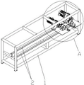
Fig. 1 is a schematic structural view of the present invention.
Fig. 2 is an enlarged schematic view at a of fig. 1.
Fig. 3 is an enlarged schematic view at B of fig. 2.
Fig. 4 shows the relative positions of the eccentric shaft and the reinforcing bar receiving rollers when the eccentric shaft is rotated to the lowermost position.
Wherein: 1. The device comprises a rack 2, a slideway 3, a sliding plate 4, a bearing seat 5, a bending assembly 6, a power input end 7, a first gear 8, a hydraulic motor 9, a power output end 10, a second gear 11, a rotating rod 12, a bending handle 13, a central shaft 14, an eccentric shaft 15, a bending station 16, a steel bar placing roller 17 and a limiting screw hole.
Detailed Description
The technical solution of the present invention will be further described with reference to the following examples.
As shown in fig. 1-3, the hydraulic motor double-head hoop bending machine comprises a frame 1, a left-right direction slideway 2 is arranged on the frame, two sliding plates 3 are arranged on the slideways, a bearing seat 4 is arranged on each sliding plate, a bending assembly 5 is arranged in each bearing seat, and the bending assembly is provided with a power input end 6 at the front end and is characterized in that: the power input end is provided with a first gear 7, the rack is also provided with two hydraulic motors 8, each hydraulic motor is provided with a power output end 9, the power output ends are provided with second gears 10, and the second gears are meshed with the first gears.
The using method comprises the following steps: the technical scheme of the utility model is realized by firstly opening the left and right sliding plates, adjusting the relative positions of the two sliding plates, adjusting the relative position of the bending assembly, then putting the steel bar on the bending assembly, opening the hydraulic motor, enabling the hydraulic motor to rotate the power output end, further enabling the second gear to rotate, further enabling the first gear to rotate, enabling the power input end to rotate along with the first gear, and enabling the bending assembly to rotate, thereby bending the steel bar; the utility model has the advantages of accurate control of the bending angle of the reinforcing steel bar and low cost because of adopting the hydraulic motor as power.
Further, crooked assembly include bull stick 11, the bull stick install in the bearing frame and can freely rotate in the bearing frame, first gear fixed mounting in the rear end of bull stick, the front end of bull stick is installed bent handle 12, has crooked station on the bent handle.
Further, the front of the crank has a central axis 13 coaxial with the turning bar and an eccentric axis 14 on one side of the central axis, between which is a bending station 15.
The concrete structure of crooked assembly has so set up, during the use, puts the reinforcing bar on two crooked stations, opens two hydraulic motor, and the eccentric shaft on each crooked handle is rotatory around the center pin, has just carried out the bending to the reinforcing bar.
Further, reinforcing steel bar placing rollers 16 are arranged on the two sliding plates, the two reinforcing steel bar placing rollers are arranged on the inner sides of the two bending assemblies, the length direction of the reinforcing steel bar placing rollers is the front-back direction, the reinforcing steel bar placing rollers can freely rotate around the axes of the reinforcing steel bar placing rollers, and the two reinforcing steel bar placing rollers are on the same horizontal line.
Furthermore, a limiting screw hole 17 is formed in the sliding plate, a limiting screw is arranged in the limiting screw hole, and the limiting screw is screwed downwards to enable the sliding plate to be relatively fixed on the slide way.
Therefore, the sliding plate can be fixed more conveniently when needing to be fixed.
While the utility model has been described with reference to specific embodiments, it will be understood by those skilled in the art that various changes in form and details may be made therein without departing from the spirit and scope of the utility model.
Claims (6)
1. Hydraulic motor duplex head hoop bending machine, including the frame, the slide of direction about the shelf location is installed, and two slides in addition are installed on the slide, install the bearing frame on every slide, every install crooked assembly in the bearing frame, crooked assembly the power input end of front end, characterized by have: the power input end is provided with a first gear, the rack is also provided with two hydraulic motors, each hydraulic motor is provided with a power output end, the power output end is provided with a second gear, and the second gear is meshed with the first gear.
2. The hydraulic motor double-head hoop bending machine as claimed in claim 1, wherein: the bending assembly comprises a rotating rod, the rotating rod is installed in the bearing seat and can freely rotate in the bearing seat, the first gear is fixedly installed at the rear end of the rotating rod, a bending handle is installed at the front end of the rotating rod, and a bending station is arranged on the bending handle.
3. The hydraulic motor double-head hoop bending machine as claimed in claim 2, wherein: the front of the crank is provided with a central shaft and an eccentric shaft, the central shaft is coaxial with the rotating rod, the eccentric shaft is arranged on one side of the central shaft, and a bending station is arranged between the central shaft and the eccentric shaft.
4. The hydraulic motor double-head hoop bending machine as claimed in claim 1, 2 or 3, wherein: the two sliding plates are provided with reinforcing steel bar placing rollers, the two reinforcing steel bar placing rollers are arranged on the inner sides of the two bending assemblies, the length direction of the reinforcing steel bar placing rollers is the front-back direction, the reinforcing steel bar placing rollers can freely rotate around the axis of the reinforcing steel bar placing rollers, and the relative heights of the two reinforcing steel bar placing rollers are on the same horizontal line.
5. The hydraulic motor double-head hoop bending machine according to claim 1, 2 or 3, which is characterized in that: the sliding plate is provided with a limiting screw hole, a limiting screw is arranged in the limiting screw hole, and the limiting screw is screwed downwards, so that the sliding plate can be relatively fixed on the slide way.
6. The hydraulic motor double-head hoop bending machine as claimed in claim 4, wherein: the sliding plate is provided with a limiting screw hole, a limiting screw is arranged in the limiting screw hole, and the limiting screw is screwed downwards to enable the sliding plate to be relatively fixed on the slide way.
Priority Applications (1)
| Application Number | Priority Date | Filing Date | Title |
|---|---|---|---|
| CN202220396762.8U CN216938139U (en) | 2022-02-26 | 2022-02-26 | Hydraulic motor double-machine-head hoop bending machine |
Applications Claiming Priority (1)
| Application Number | Priority Date | Filing Date | Title |
|---|---|---|---|
| CN202220396762.8U CN216938139U (en) | 2022-02-26 | 2022-02-26 | Hydraulic motor double-machine-head hoop bending machine |
Publications (1)
| Publication Number | Publication Date |
|---|---|
| CN216938139U true CN216938139U (en) | 2022-07-12 |
Family
ID=82292316
Family Applications (1)
| Application Number | Title | Priority Date | Filing Date |
|---|---|---|---|
| CN202220396762.8U Active CN216938139U (en) | 2022-02-26 | 2022-02-26 | Hydraulic motor double-machine-head hoop bending machine |
Country Status (1)
| Country | Link |
|---|---|
| CN (1) | CN216938139U (en) |
-
2022
- 2022-02-26 CN CN202220396762.8U patent/CN216938139U/en active Active
Similar Documents
| Publication | Publication Date | Title |
|---|---|---|
| CN207013495U (en) | Has the bending roll machine of anti-twisting function | |
| CN103028875A (en) | Variable-angle automatic spot welding device moving along with profiling track | |
| CN212397669U (en) | Automatic pointing production equipment | |
| CN215279641U (en) | Automatic bar straightener who derusts in advance | |
| CN113146216B (en) | Positioning gasket screw machine | |
| CN213856799U (en) | Spring production processingequipment | |
| CN212144635U (en) | Drilling equipment of motorcycle accessories processing usefulness | |
| CN220278133U (en) | An automatic hook and hoop bending machine with two ends | |
| CN222242049U (en) | Flexible bending machine for sheet metal | |
| CN112238264A (en) | Gear shaping device for gear machining for aerospace | |
| CN219027523U (en) | Mechanical production line helping hand arm | |
| CN201189541Y (en) | Steel bar automatic bending machine | |
| CN108428548B (en) | Automatic insulating cloth winding robot for rectangular coils of motor | |
| CN210232614U (en) | Polishing device for blank pipe of copper pipe of crystallizer | |
| CN201603787U (en) | Opening-closing type forming mill | |
| CN115870427A (en) | Multifunctional Bending Machine | |
| CN208019595U (en) | A kind of workpiece guided cutting apparatus | |
| CN202752485U (en) | Manual feeding device in fully automatic numerical control hydraulic pipe bending machine | |
| CN216540610U (en) | Horizontal bending five-machine-head hoop bending machine | |
| CN202683699U (en) | Three-roller swing mechanism of hydraulic section-bar bending machine | |
| CN218310234U (en) | Metal bar bending machine | |
| CN220612895U (en) | Automatic assembly device for automobile motor mandrel | |
| CN223070339U (en) | Straightening cutter convenient to maintain | |
| CN218983344U (en) | Cutting device for metal profile machining | |
| CN201161274Y (en) | Automatic dual-folding machine for steel bar |
Legal Events
| Date | Code | Title | Description |
|---|---|---|---|
| GR01 | Patent grant | ||
| GR01 | Patent grant |