CN216930397U - Intelligent printed circuit board with high temperature resistant function - Google Patents
Intelligent printed circuit board with high temperature resistant function Download PDFInfo
- Publication number
- CN216930397U CN216930397U CN202123373546.6U CN202123373546U CN216930397U CN 216930397 U CN216930397 U CN 216930397U CN 202123373546 U CN202123373546 U CN 202123373546U CN 216930397 U CN216930397 U CN 216930397U
- Authority
- CN
- China
- Prior art keywords
- circuit board
- high temperature
- printed circuit
- heat dissipation
- heat
- Prior art date
- Legal status (The legal status is an assumption and is not a legal conclusion. Google has not performed a legal analysis and makes no representation as to the accuracy of the status listed.)
- Active
Links
- XLYOFNOQVPJJNP-UHFFFAOYSA-N water Substances O XLYOFNOQVPJJNP-UHFFFAOYSA-N 0.000 claims abstract description 36
- 230000017525 heat dissipation Effects 0.000 claims abstract description 30
- 238000001816 cooling Methods 0.000 claims description 10
- 238000005192 partition Methods 0.000 claims description 5
- 239000000428 dust Substances 0.000 claims 1
- 230000004089 microcirculation Effects 0.000 abstract description 5
- 239000007788 liquid Substances 0.000 description 4
- 238000010586 diagram Methods 0.000 description 2
- 230000009286 beneficial effect Effects 0.000 description 1
- 238000011161 development Methods 0.000 description 1
- 238000005516 engineering process Methods 0.000 description 1
- 238000012423 maintenance Methods 0.000 description 1
- 238000000034 method Methods 0.000 description 1
- 238000012986 modification Methods 0.000 description 1
- 230000004048 modification Effects 0.000 description 1
- 238000007789 sealing Methods 0.000 description 1
- 238000012546 transfer Methods 0.000 description 1
Images


Classifications
-
- Y—GENERAL TAGGING OF NEW TECHNOLOGICAL DEVELOPMENTS; GENERAL TAGGING OF CROSS-SECTIONAL TECHNOLOGIES SPANNING OVER SEVERAL SECTIONS OF THE IPC; TECHNICAL SUBJECTS COVERED BY FORMER USPC CROSS-REFERENCE ART COLLECTIONS [XRACs] AND DIGESTS
- Y02—TECHNOLOGIES OR APPLICATIONS FOR MITIGATION OR ADAPTATION AGAINST CLIMATE CHANGE
- Y02D—CLIMATE CHANGE MITIGATION TECHNOLOGIES IN INFORMATION AND COMMUNICATION TECHNOLOGIES [ICT], I.E. INFORMATION AND COMMUNICATION TECHNOLOGIES AIMING AT THE REDUCTION OF THEIR OWN ENERGY USE
- Y02D10/00—Energy efficient computing, e.g. low power processors, power management or thermal management
Landscapes
- Cooling Or The Like Of Electrical Apparatus (AREA)
Abstract
本实用新型涉及电路板技术领域,且公开了一种具有耐高温功能的智能印制电路板,包括壳体和电路板主体,所述电路板主体固定设置于壳体的内部上端,所述电路板主体的下表面固定设置有导热板,所述壳体的内部设置有两个空心板,两个所述空心板之间固定连接有多个散热管,多个所述散热管的均与导热板相抵触,所述壳体的底部设置有储水壳,所述储水壳的内部两端分别固定设置有出水管和进水管,所述出水管和进水管的上端均与对应的空心板固定连接,所述储水壳的内部设置有微型循环泵,所述出水管的下端与微型循环泵的出水口固定连接。本实用新型具有良好的散热性能,能够大大提高电路板的耐高温性能。
The utility model relates to the technical field of circuit boards, and discloses an intelligent printed circuit board with high temperature resistance function. A heat-conducting plate is fixedly arranged on the lower surface of the plate main body, and two hollow plates are arranged inside the casing, and a plurality of heat dissipation pipes are fixedly connected between the two hollow plates, and the plurality of heat-dissipating pipes are all connected to the heat conduction. The bottom of the shell is provided with a water storage shell, the inner two ends of the water storage shell are respectively fixed with a water outlet pipe and a water inlet pipe, and the upper ends of the water outlet pipe and the water inlet pipe are both connected with the corresponding hollow plates Fixed connection, the inside of the water storage shell is provided with a micro circulation pump, and the lower end of the water outlet pipe is fixedly connected with the water outlet of the micro circulation pump. The utility model has good heat dissipation performance and can greatly improve the high temperature resistance performance of the circuit board.
Description
技术领域technical field
本实用新型涉及电路板技术领域,尤其涉及一种具有耐高温功能的智能印制电路板。The utility model relates to the technical field of circuit boards, in particular to an intelligent printed circuit board with a high temperature resistance function.
背景技术Background technique
印制电路板在日常生活中较为常见,随着科技的发展,智能印制电路板上安装的电子元件数量越来越多,工作时产生的热量越来越多。Printed circuit boards are more common in daily life. With the development of science and technology, the number of electronic components installed on intelligent printed circuit boards is increasing, and the heat generated during work is increasing.
传统的智能印制电路板大多都是依靠空气自然散热,散热效率低,耐高温性能差,在高温环境下工作时,会积累大量的热量导致印制电路板造成损坏,造成经济损失。Most of the traditional smart printed circuit boards rely on air to dissipate heat naturally, with low heat dissipation efficiency and poor high temperature resistance. When working in a high temperature environment, a large amount of heat will accumulate, causing damage to the printed circuit board, resulting in economic losses.
实用新型内容Utility model content
本实用新型的目的是为了解决现有技术中智能印制电路板大多都是依靠空气自然散热,散热效率低,耐高温性能差的问题,而提出的一种具有耐高温功能的智能印制电路板。The purpose of the utility model is to solve the problems that most of the intelligent printed circuit boards in the prior art rely on air to dissipate heat naturally, the heat dissipation efficiency is low, and the high temperature resistance performance is poor, and an intelligent printed circuit with high temperature resistance function is proposed. plate.
为了实现上述目的,本实用新型采用了如下技术方案:In order to achieve the above-mentioned purpose, the utility model adopts the following technical scheme:
一种具有耐高温功能的智能印制电路板,包括壳体和电路板主体,所述电路板主体固定设置于壳体的内部上端,所述电路板主体的下表面固定设置有导热板,所述壳体的内部设置有两个空心板,两个所述空心板之间固定连接有多个散热管,多个所述散热管的均与导热板相抵触,所述壳体的底部设置有储水壳,所述储水壳的内部两端分别固定设置有出水管和进水管,所述出水管和进水管的上端均与对应的空心板固定连接,所述储水壳的内部设置有微型循环泵,所述出水管的下端与微型循环泵的出水口固定连接,所述壳体的下端两侧均开设有散热槽,所述散热管的内部设置有散热机构。An intelligent printed circuit board with high temperature resistance function includes a casing and a circuit board main body, the circuit board main body is fixedly arranged on the inner upper end of the casing, and a heat conduction plate is fixedly arranged on the lower surface of the circuit board main body, so the The interior of the casing is provided with two hollow plates, a plurality of heat dissipation pipes are fixedly connected between the two hollow plates, and the plurality of heat dissipation pipes are all in conflict with the heat conduction plate, and the bottom of the casing is provided with a plurality of heat dissipation pipes. The water storage shell, the inner two ends of the water storage shell are respectively fixed with a water outlet pipe and a water inlet pipe, and the upper ends of the water outlet pipe and the water inlet pipe are fixedly connected with the corresponding hollow plates, and the interior of the water storage shell is provided with a water outlet pipe and a water inlet pipe. In the micro-circulating pump, the lower end of the water outlet pipe is fixedly connected with the water outlet of the micro-circulating pump, the lower end of the casing is provided with cooling grooves on both sides, and the cooling mechanism is arranged inside the cooling pipe.
优选的,所述所述散热机构包括转杆和扇叶,所述转杆转动设置于散热管的内部,所述转杆的有一端延伸至散热管的外侧,所述扇叶固定套设于转杆的外侧一端,所述转杆的内侧一端侧壁固定设置有多个挡板,所述散热管的中部固定设置有隔板,所述隔板的上侧开设有通槽。Preferably, the heat dissipation mechanism includes a rotating rod and a fan blade, the rotating rod is rotatably arranged inside the heat dissipation pipe, one end of the rotating rod extends to the outside of the heat dissipation pipe, and the fan blade is fixedly sleeved on the inside of the heat dissipation pipe. A plurality of baffles are fixedly arranged on the side wall of the inner end of the rotating rod, the middle part of the heat dissipation pipe is fixedly provided with a baffle, and the upper side of the baffle is provided with a through groove.
优选的,所述壳体的两侧均开设有通槽。Preferably, both sides of the casing are provided with through grooves.
优选的,所述转杆通过密封轴承与散热管转动连接。Preferably, the rotating rod is rotatably connected to the cooling pipe through a sealed bearing.
优选的,两个所述通槽的内部均固定设置有防尘网。Preferably, the interiors of the two through grooves are fixedly provided with dust-proof nets.
优选的,所述电路板主体通过螺钉与壳体固定连接。Preferably, the main body of the circuit board is fixedly connected to the housing through screws.
与现有技术相比,本实用新型提供了一种具有耐高温功能的智能印制电路板,具备以下有益效果:Compared with the prior art, the utility model provides an intelligent printed circuit board with high temperature resistance function, which has the following beneficial effects:
该具有耐高温功能的智能印制电路板,通过导热板对电路板主体热量进行吸收,然后微型循环泵对散热管内的液体进行循环,使得散热管对导热板进行散热,散热管内液体流动推动挡板,即使得转杆带动扇叶转动,即能够加快壳体内的空气流动,即对电路板主体进行高效的散热,能够大大提高电路板主体的耐高温性能。The intelligent printed circuit board with high temperature resistance function absorbs the heat of the main body of the circuit board through the heat conduction plate, and then the micro circulation pump circulates the liquid in the heat dissipation pipe, so that the heat dissipation pipe can dissipate heat to the heat conduction plate, and the liquid flow in the heat dissipation pipe pushes the block Even if the rotating rod drives the fan blades to rotate, the air flow in the casing can be accelerated, that is, the heat dissipation of the circuit board body can be efficiently performed, and the high temperature resistance performance of the circuit board body can be greatly improved.
该装置中未涉及部分均与现有技术相同或可采用现有技术加以实现,本实用新型具有良好的散热性能,能够大大提高电路板的耐高温性能。The parts not involved in the device are the same as the prior art or can be realized by adopting the prior art. The utility model has good heat dissipation performance and can greatly improve the high temperature resistance performance of the circuit board.
附图说明Description of drawings
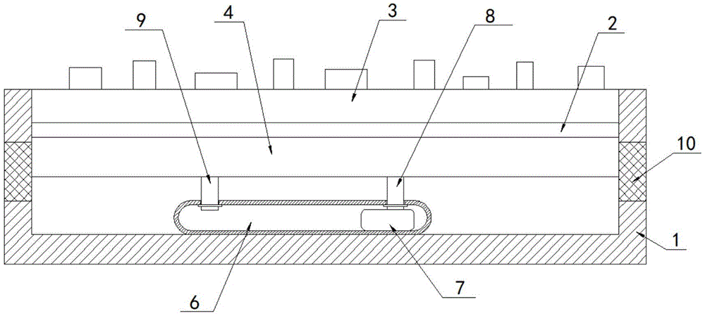
图1为本实用新型提出的一种具有耐高温功能的智能印制电路板的结构示意图;1 is a schematic structural diagram of an intelligent printed circuit board with a high temperature resistance function proposed by the utility model;
图2为图1的内部结构示意图。FIG. 2 is a schematic diagram of the internal structure of FIG. 1 .
图中:1壳体、2导热板、3电路板主体、4空心板、5散热管、6储水壳、7微型循环泵、8出水管、9进水管、10防尘网、11隔板、12转杆、13扇叶、14挡板。In the picture: 1 shell, 2 heat conduction plate, 3 circuit board main body, 4 hollow plate, 5 heat pipe, 6 water storage shell, 7 micro circulation pump, 8 water outlet pipe, 9 water inlet pipe, 10 dustproof net, 11 partition plate , 12 levers, 13 blades, 14 baffles.
具体实施方式Detailed ways
下面将结合本实用新型实施例中的附图,对本实用新型实施例中的技术方案进行清楚、完整地描述,显然,所描述的实施例仅仅是本实用新型一部分实施例,而不是全部的实施例。The technical solutions in the embodiments of the present utility model will be clearly and completely described below with reference to the accompanying drawings in the embodiments of the present utility model. Obviously, the described embodiments are only a part of the embodiments of the present utility model, rather than all the implementations. example.
在本实用新型的描述中,需要理解的是,术语“上”、“下”、“前”、“后”、“左”、“右”、“顶”、“底”、“内”、“外”等指示的方位或位置关系为基于附图所示的方位或位置关系,仅是为了便于描述本实用新型和简化描述,而不是指示或暗示所指的装置或元件必须具有特定的方位、以特定的方位构造和操作,因此不能理解为对本实用新型的限制。In the description of the present invention, it should be understood that the terms "upper", "lower", "front", "rear", "left", "right", "top", "bottom", "inside", The orientation or positional relationship indicated by "outside" is based on the orientation or positional relationship shown in the accompanying drawings, which is only for the convenience of describing the present invention and simplifying the description, rather than indicating or implying that the indicated device or element must have a specific orientation , are constructed and operated in a specific orientation, and therefore should not be construed as a limitation of the present invention.
参照图1-2,一种具有耐高温功能的智能印制电路板,包括壳体1和电路板主体3,电路板主体3固定设置于壳体1的内部上端,电路板主体3的下表面固定设置有导热板2,壳体1的内部设置有两个空心板4,两个空心板4之间固定连接有多个散热管5,多个散热管5的均与导热板2相抵触,壳体1的底部设置有储水壳6,储水壳6的内部两端分别固定设置有出水管8和进水管9,出水管8和进水管9的上端均与对应的空心板4固定连接,储水壳6的内部设置有微型循环泵7,出水管8的下端与微型循环泵7的出水口固定连接,壳体1的下端两侧均开设有散热槽,散热管5的内部设置有散热机构。1-2, an intelligent printed circuit board with high temperature resistance function includes a
散热机构包括转杆12和扇叶13,转杆12转动设置于散热管5的内部,转杆12的有一端延伸至散热管5的外侧,扇叶13固定套设于转杆12的外侧一端,转杆12的内侧一端侧壁固定设置有多个挡板14,散热管5的中部固定设置有隔板11,隔板11的上侧开设有通槽。The heat dissipation mechanism includes a rotating rod 12 and a
壳体1的两侧均开设有通槽,方便壳体1内空气流动。Both sides of the
转杆12通过密封轴承与散热管5转动连接,提高转杆12与散热管5之间的密封性。The rotating rod 12 is rotatably connected to the
两个通槽的内部均固定设置有防尘网10,提高壳体1的防尘性能。The inside of the two through grooves are fixedly provided with a
电路板主体3通过螺钉与壳体1固定连接,方便对电路板主体3进行拆卸维护。The circuit board
本实用新型中,使用时,由于导热板2对电路板主体3热量进行吸收,然后微型循环泵7对散热管5和储水壳6内的液体进行循环,使得散热管5对导热板2进行高效散热,散热管5内液体流动推动挡板14,即使得转杆12带动扇叶13转动,即能够加快壳体1内的空气流动,即对电路板主体3进行高效的散热,能够大大提高电路板主体3的耐高温性能。In the present invention, when in use, since the heat-conducting
以上所述,仅为本实用新型较佳的具体实施方式,但本实用新型的保护范围并不局限于此,任何熟悉本技术领域的技术人员在本实用新型揭露的技术范围内,根据本实用新型的技术方案及其实用新型构思加以等同替换或改变,都应涵盖在本实用新型的保护范围之内。The above are only the preferred specific embodiments of the present invention, but the protection scope of the present invention is not limited to this. Equivalent replacement or modification of the new technical solution and its utility model concept shall be included within the protection scope of the present utility model.
Claims (6)
Priority Applications (1)
| Application Number | Priority Date | Filing Date | Title |
|---|---|---|---|
| CN202123373546.6U CN216930397U (en) | 2021-12-29 | 2021-12-29 | Intelligent printed circuit board with high temperature resistant function |
Applications Claiming Priority (1)
| Application Number | Priority Date | Filing Date | Title |
|---|---|---|---|
| CN202123373546.6U CN216930397U (en) | 2021-12-29 | 2021-12-29 | Intelligent printed circuit board with high temperature resistant function |
Publications (1)
| Publication Number | Publication Date |
|---|---|
| CN216930397U true CN216930397U (en) | 2022-07-08 |
Family
ID=82254561
Family Applications (1)
| Application Number | Title | Priority Date | Filing Date |
|---|---|---|---|
| CN202123373546.6U Active CN216930397U (en) | 2021-12-29 | 2021-12-29 | Intelligent printed circuit board with high temperature resistant function |
Country Status (1)
| Country | Link |
|---|---|
| CN (1) | CN216930397U (en) |
-
2021
- 2021-12-29 CN CN202123373546.6U patent/CN216930397U/en active Active
Similar Documents
| Publication | Publication Date | Title |
|---|---|---|
| CN112004373A (en) | Novel server cabinet heat dissipation device | |
| CN208999940U (en) | A computer water cooling system based on dual mainboard structure | |
| CN207589404U (en) | Liquid-cooled cabinet for electronic equipment | |
| CN218526172U (en) | Linear motor with double cooling | |
| CN211823459U (en) | A new type of circulating cooling water tank | |
| CN218728904U (en) | Computer mainframe capable of circularly radiating | |
| CN213782696U (en) | Cooling device for power distribution cabinet | |
| TWI578887B (en) | Volume change heat dissipation system | |
| CN220493453U (en) | Balanced heat abstractor of electromechanical device | |
| CN206819278U (en) | A water-cooled radiator for a notebook motherboard | |
| CN112781132B (en) | Double heat dissipation structure of air cooler and air cooler | |
| CN214281578U (en) | A ventilation and heat dissipation type Internet vertical switch | |
| CN210776536U (en) | A computer case with recirculating heat dissipation | |
| CN212231949U (en) | Novel liquid-cooled cabinet | |
| CN209017391U (en) | A new type of big data device | |
| CN112987875A (en) | Can dustproof radiating computer mainframe | |
| CN209803717U (en) | Computer machine case convenient to heat dissipation | |
| CN209462838U (en) | A kind of liquid-immersed cooled interchanger and group of switches | |
| CN209248447U (en) | Computer water-cooling heat abstractor | |
| CN216626496U (en) | Water-cooling heat dissipation plate | |
| CN222562004U (en) | A computer dual heat dissipation device | |
| CN220173694U (en) | Internet of things data analyzer | |
| CN219642204U (en) | Heat radiation structure for computer host | |
| CN218497453U (en) | cooling device for computer | |
| CN218095851U (en) | A LED lamp bracket with heat dissipation function |
Legal Events
| Date | Code | Title | Description |
|---|---|---|---|
| GR01 | Patent grant | ||
| GR01 | Patent grant | ||
| TR01 | Transfer of patent right |
Effective date of registration: 20250321 Address after: 341600 Building 2, Xinda circuit technology park, Lvyuan Avenue, Xinfeng Industrial Park, Ganzhou City, Jiangxi Province Patentee after: XINFENG HUIHE CIRCUIT Co.,Ltd. Country or region after: China Address before: 518103 room 311, building 1, zone 2, Sanxing Industrial Zone, Fuyong community, Fuyong street, Bao'an District, Shenzhen, Guangdong Province Patentee before: Shenzhen tongchuangxin Electronic Technology Co.,Ltd. Country or region before: China |
|
| TR01 | Transfer of patent right |