Multifunctional distribution box
Technical Field
The utility model belongs to the technical field of electric power facilities, and particularly relates to a multifunctional distribution box.
Background
Nowadays, in order to facilitate centralized control of electric power, a distribution box is generally used, and mass parameters on data of the distribution box generally form a low-voltage forest according to electrical wiring, and a switching device, a measuring instrument, a protection electric appliance and auxiliary equipment are required to be assembled in a closed or semi-closed metal cabinet or on a screen to form the low-voltage distribution box, and a circuit can be switched on or switched off by means of a manual or automatic switch in normal operation.
At present, the utility model with patent number CN202121277146.2 discloses a multifunctional distribution box, which comprises a box body, a detachable cover is arranged at the top end of the box body, a fixed plate is fixedly arranged on the inner side wall of the box body, a first through hole is arranged at the top of the fixed plate, a first connecting rod is hinged on the right wall of the interior of the box body, a second connecting rod is hinged at the left end of the first connecting rod, a spring is hinged on the side wall of the first connecting rod, the left end of the spring is hinged on the side wall of the second connecting rod, and a vertical plate is hinged at the left end of the second connecting rod. Realize in time remedying, avoid the conflagration to take place to cause by the damage of block terminal dispersion circuit, reduce the loss. What its adopted is to take a breath through the dislocation hole and handles, but this block terminal is in the use, can not carry out the heat dissipation processing to inside when rain-proof, and can not carry out automatic switch to equipment and handle.
Therefore, to the problem that the aforesaid daily multi-functional block terminal can not prevent rain heat dissipation after using, need to be solved urgently to improve the practicality of device.
SUMMERY OF THE UTILITY MODEL
(1) Technical problem to be solved
Aiming at the defects of the prior art, the utility model aims to provide a multifunctional distribution box, which aims to solve the technical problems that the interior of the distribution box can not be subjected to heat dissipation treatment while being rainproof and the equipment can not be subjected to automatic switching treatment in the prior art.
(2) Technical scheme
In order to solve the technical problems, the utility model provides the multifunctional distribution box, which comprises a box body; the outside fixed mounting of box has waterproof component, waterproof component is provided with two sets ofly, the outside fixed mounting of box has rainshelter, the inboard of box is provided with equipment principal, the inboard bottom of box is provided with logical line hole, the inboard bottom of box is provided with radiator unit, the inboard of box is provided with drive assembly, drive assembly's the outside is provided with the door plant, the door plant with the inboard sliding connection of box.
When the multifunctional distribution box of the technical scheme is used, the rainproof exhaust effect is played through the setting of the waterproof assembly, the heat dissipation treatment is carried out through the setting of the heat dissipation assembly, the automatic switch is carried out on the door plate through the setting of the driving assembly, and therefore the rainproof heat dissipation and the automatic switch treatment of equipment are achieved.
Preferably, the inside of the waterproof assembly comprises an inclined baffle, the inclined baffle is fixedly installed on the outer side of the box body, an angle folding groove is formed in the inner side of the inclined baffle, the angle folding groove is communicated with the inside of the box body, rain-proof treatment is carried out through the arrangement of the inclined baffle, air is exhausted from the inside of the box body through the arrangement of the angle folding groove, and meanwhile rainwater backflow is prevented.
Preferably, the inside of the heat dissipation assembly comprises heat dissipation fans, the heat dissipation fans are arranged at the bottom end of the inner side of the box body, the heat dissipation fans are arranged in two groups, and air blowing and heat dissipation treatment are carried out through the heat dissipation fans.
Further, radiator unit's inside is including the filter screen, the filter screen set up in the inboard bottom of box, the filter screen is located the bottom of heat dissipation fan filters the air through the setting of filter screen.
Preferably, the driving assembly comprises a limiting groove, the limiting groove is formed in the inner side of the box body, the limiting groove is provided with two groups, the limiting groove is in sliding connection with the door plate, and the door plate is subjected to moving limiting treatment through sliding connection of the door plate and the limiting groove.
Furthermore, the inside of drive assembly is including the rack, the rack set up in the outside of door plant, the inboard bottom of box is provided with the motor, the output shaft fixed mounting of motor has the gear, the gear with the rack meshing is connected, drives the gear through starter motor and rotates, is connected through the meshing of gear and rack and drives the door plant and slide along the spacing groove.
(3) Advantageous effects
Compared with the prior art, the utility model has the beneficial effects that: the multifunctional distribution box disclosed by the utility model is used for carrying out rainproof treatment through the arrangement of the inclined baffle, exhausting is carried out inside the box body through the arrangement of the corner groove, rainwater backflow is prevented, air is filtered through the arrangement of the filter screen, the air blowing and heat dissipating treatment is carried out through the arrangement of the heat dissipating fan, the gear is driven to rotate through the starting motor, the door plate is driven to slide along the limiting groove through the meshing connection of the gear and the rack, and the door plate is moved and limited through the sliding connection of the door plate and the limiting groove, so that the rainproof heat dissipation and the automatic switching treatment of equipment are realized.
Drawings
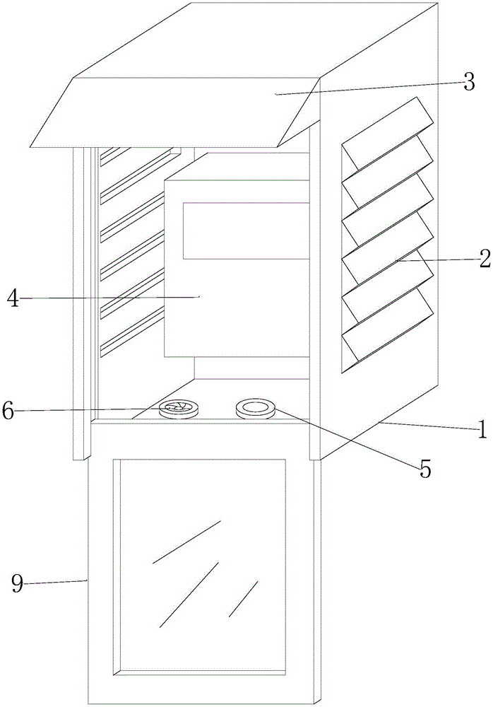
FIG. 1 is a schematic perspective view of an embodiment of the present invention;
FIG. 2 is a schematic side view cross-section of one embodiment of the present invention;
FIG. 3 is a schematic top view of a cross-section of an embodiment of the present invention.
The symbols in the drawings are: 1. a box body; 2. a waterproof assembly; 3. a rain shelter; 4. an apparatus main body; 5. a through hole; 6. a heat dissipating component; 8. a drive assembly; 9. a door panel; 10. an inclined baffle plate; 11. a corner groove; 12. a heat dissipation fan; 13. a filter screen; 14. a limiting groove; 15. a rack rail; 16. a motor; 17. a gear.
Detailed Description
Example 1
The multifunctional distribution box comprises a box body 1, a box cover and a box cover, wherein the three-dimensional structure schematic diagram of the multifunctional distribution box is shown in figure 1, and the side-view section structure schematic diagram of the multifunctional distribution box is shown in figure 2; the outside fixed mounting of box 1 has waterproof component 2, and waterproof component 2 is provided with two sets ofly, and the outside fixed mounting of box 1 has rainshelter 3, and the inboard of box 1 is provided with equipment principal 4, and the inboard bottom of box 1 is provided with logical line hole 5, and the inboard bottom of box 1 is provided with radiator unit 6, and the inboard of box 1 is provided with drive assembly 8, and drive assembly 8's the outside is provided with door plant 9, door plant 9 and box 1's inboard sliding connection.
For the present embodiment, the shape and structure of the box 1 are set according to practical application, for example, the box 1 may have a rectangular structure, an arc structure, a polygonal structure, and the like.
Wherein, the inside of water repellent component 2 is including oblique baffle 10, oblique baffle 10 fixed mounting is in the outside of box 1, dog-ear groove 11 has been seted up to the inboard of oblique baffle 10, dog-ear groove 11 and the inside intercommunication of box 1, carry out rain-proof processing through the setting of oblique baffle 10, set up through dog-ear groove 11 and exhaust to the inside of box 1, prevent the rainwater backward flow simultaneously, the inside of radiator unit 6 is including heat dissipation fan 12, heat dissipation fan 12 sets up in the inboard bottom of box 1, heat dissipation fan 12 is provided with two sets ofly, the heat treatment of loosing of blowing is carried out through the setting of heat dissipation fan 12.
This embodiment is used for multi-functional block terminal, it looks down the section structure sketch map as shown in fig. 3, radiator unit 6's inside is including filter screen 13, filter screen 13 sets up in the inboard bottom of box 1, filter screen 13 is located the bottom of heat dissipation fan 12, set up through filter screen 13 and filter the air, drive assembly 8's inside is including spacing groove 14, spacing groove 14 is seted up in the inboard of box 1, two sets of have been seted up to spacing groove 14, spacing groove 14 and door plant 9 sliding connection, sliding connection through door plant 9 and spacing groove 14 removes spacing processing to door plant 9.
Simultaneously, the inside of drive assembly 8 is including rack 15, rack 15 sets up in the outside of door plant 9, and the inboard bottom of box 1 is provided with motor 16, and motor 16's output shaft fixed mounting has gear 17, and gear 17 is connected with rack 15 meshing, drives gear 17 through starter motor 16 and rotates, is connected through gear 17 and rack 15's meshing and drives door plant 9 and slide along spacing groove 14.
Use this technical scheme's multifunctional distribution box during, carry out rain-proof processing through the setting of oblique baffle 10, setting through dog-ear groove 11 is discharged to the inside of box 1, prevent the rainwater backward flow simultaneously, the setting through filter screen 13 filters the air, the scattered thermal treatment of blowing is carried out through the setting of heat dissipation fan 12, it rotates to drive gear 17 through starter motor 16, it slides along spacing groove 14 to be connected drive door plant 9 through gear 17 and the meshing of cogged rail 15, sliding connection through door plant 9 and spacing groove 14 removes spacing processing to door plant 9, thereby realized the rain-proof heat dissipation and the automatic switch of equipment and handled.