CN216924079U - Lamp body, lamp and head-shaking lamp - Google Patents
Lamp body, lamp and head-shaking lamp Download PDFInfo
- Publication number
- CN216924079U CN216924079U CN202220184400.2U CN202220184400U CN216924079U CN 216924079 U CN216924079 U CN 216924079U CN 202220184400 U CN202220184400 U CN 202220184400U CN 216924079 U CN216924079 U CN 216924079U
- Authority
- CN
- China
- Prior art keywords
- heat
- cavity
- radiator
- heat exchange
- light source
- Prior art date
- Legal status (The legal status is an assumption and is not a legal conclusion. Google has not performed a legal analysis and makes no representation as to the accuracy of the status listed.)
- Active
Links
- 230000017525 heat dissipation Effects 0.000 claims abstract description 84
- 239000002826 coolant Substances 0.000 claims abstract description 65
- 239000000110 cooling liquid Substances 0.000 claims abstract description 42
- 239000007788 liquid Substances 0.000 claims description 51
- 238000007789 sealing Methods 0.000 claims description 7
- 238000001816 cooling Methods 0.000 description 12
- 238000010521 absorption reaction Methods 0.000 description 9
- 238000000034 method Methods 0.000 description 8
- 238000009423 ventilation Methods 0.000 description 8
- 238000010586 diagram Methods 0.000 description 4
- 238000005192 partition Methods 0.000 description 4
- XLYOFNOQVPJJNP-UHFFFAOYSA-N water Substances O XLYOFNOQVPJJNP-UHFFFAOYSA-N 0.000 description 4
- 229910052782 aluminium Inorganic materials 0.000 description 3
- XAGFODPZIPBFFR-UHFFFAOYSA-N aluminium Chemical compound [Al] XAGFODPZIPBFFR-UHFFFAOYSA-N 0.000 description 3
- 230000000694 effects Effects 0.000 description 3
- 238000000605 extraction Methods 0.000 description 3
- 239000012530 fluid Substances 0.000 description 3
- 238000009434 installation Methods 0.000 description 3
- 230000005855 radiation Effects 0.000 description 3
- RYGMFSIKBFXOCR-UHFFFAOYSA-N Copper Chemical compound [Cu] RYGMFSIKBFXOCR-UHFFFAOYSA-N 0.000 description 2
- 229910052802 copper Inorganic materials 0.000 description 2
- 239000010949 copper Substances 0.000 description 2
- 238000010438 heat treatment Methods 0.000 description 2
- 229910052751 metal Inorganic materials 0.000 description 2
- 239000002184 metal Substances 0.000 description 2
- 230000001681 protective effect Effects 0.000 description 2
- BQCADISMDOOEFD-UHFFFAOYSA-N Silver Chemical compound [Ag] BQCADISMDOOEFD-UHFFFAOYSA-N 0.000 description 1
- 230000002528 anti-freeze Effects 0.000 description 1
- 230000009286 beneficial effect Effects 0.000 description 1
- 230000002146 bilateral effect Effects 0.000 description 1
- 230000000052 comparative effect Effects 0.000 description 1
- PCHJSUWPFVWCPO-UHFFFAOYSA-N gold Chemical compound [Au] PCHJSUWPFVWCPO-UHFFFAOYSA-N 0.000 description 1
- 229910052737 gold Inorganic materials 0.000 description 1
- 239000010931 gold Substances 0.000 description 1
- 230000007774 longterm Effects 0.000 description 1
- 239000000463 material Substances 0.000 description 1
- 238000012986 modification Methods 0.000 description 1
- 230000004048 modification Effects 0.000 description 1
- 238000004806 packaging method and process Methods 0.000 description 1
- 229910052709 silver Inorganic materials 0.000 description 1
- 239000004332 silver Substances 0.000 description 1
- 239000007787 solid Substances 0.000 description 1
- 238000004078 waterproofing Methods 0.000 description 1
Images




Landscapes
- Arrangement Of Elements, Cooling, Sealing, Or The Like Of Lighting Devices (AREA)
Abstract
本实用新型涉及照明领域,公开了一种灯体以及具有该灯体的灯具,灯体包括壳体、光源和散热器,壳体包括密闭设置的第一腔体;光源设于第一腔体内;散热器包括第一散热器和第二散热器;第一散热器包括冷却介质,冷却介质是气体和/或第一冷却液,冷却介质在第一腔体内与第一腔体外循环流动以用于热交换;第二散热器设于第一腔体外,第二散热器与光源的导热面连接以用于热交换。同时公开了一种摇头灯具。本实用新型具有结构紧凑、轻巧、散热高效的特点。
The utility model relates to the field of lighting, and discloses a lamp body and a lamp with the lamp body. The lamp body comprises a casing, a light source and a radiator; the casing comprises a sealed first cavity; the light source is arranged in the first cavity The radiator includes a first radiator and a second radiator; the first radiator includes a cooling medium, the cooling medium is a gas and/or a first cooling liquid, and the cooling medium circulates in the first cavity and the outside of the first cavity to use for heat exchange; the second radiator is arranged outside the first cavity, and the second radiator is connected with the heat-conducting surface of the light source for heat exchange. At the same time, a moving head lamp is disclosed. The utility model has the characteristics of compact structure, light weight and high heat dissipation.
Description
技术领域technical field
本实用新型涉及照明装置领域,具体的是一种兼具散热高效与防水的灯体及灯具。The utility model relates to the field of lighting devices, in particular to a lamp body and a lamp with both high heat dissipation efficiency and waterproofing.
背景技术Background technique
目前,市场上LED防水灯具的灯体内部热量主要是通过热传导、热辐射的方式进行冷却降温,存在以下几种情形:At present, the internal heat of the lamp body of LED waterproof lamps on the market is mainly cooled by heat conduction and heat radiation. There are the following situations:
(1)通过灯体壳体的热辐射将光源热量散发至灯体外。由于LED模组需要长时间工作,大功率光源产生的热量多且灯体密闭,仅依靠灯体壳体辐射散热不能有效带走热量,以此导致灯体内部温度过高而造成电气元件不稳定或失效。所以,通过灯体壳体辐射散热的方式是无法满足LED防水灯具的工作需要。(1) The heat of the light source is radiated to the outside of the lamp body through the thermal radiation of the lamp body shell. Because the LED module needs to work for a long time, the high-power light source generates a lot of heat and the lamp body is airtight, and only relying on the radiation heat dissipation of the lamp body shell cannot effectively take away the heat, which leads to the high internal temperature of the lamp body and the instability of the electrical components. or invalid. Therefore, the way of radiating heat through the lamp body shell cannot meet the working needs of the LED waterproof lamp.
(2)通过金属散热器将光源热量传导并散发至灯体外,例如热管散热器、型材散热器等。由于光源存在功率高、体积小、热量集中且工作时间长的特性,光源体积小则限制了金属散热器与光源的贴合面积,而腔体留给热管或鳍片的排布位置有限,以及散热器自身结构的换热效率因素,导致热交换效率低而无法有效带走光源的热量,长时间工作下积聚的热量将会导致光源寿命缩短或烧毁光源。(2) Conduct and dissipate the heat of the light source to the outside of the lamp through a metal radiator, such as a heat pipe radiator, a profile radiator, etc. Because the light source has the characteristics of high power, small size, concentrated heat and long working time, the small size of the light source limits the bonding area between the metal heat sink and the light source, and the cavity left for the arrangement of heat pipes or fins is limited, and The heat exchange efficiency factor of the radiator's own structure leads to low heat exchange efficiency and cannot effectively take away the heat of the light source. The accumulated heat under long-term operation will shorten the life of the light source or burn the light source.
例如当热管散热器或型材散热器的LED模组的功率≥1200W时,短时间内急剧升高的温度就能使电气元件不稳定,也无法及时、有效地降低灯体温度;而且散热器的体积大、质量重,导致整灯结构也无法缩减体积,以及连接灯体与灯臂的转轴组件、灯臂等还需重新设计以适应地提高刚度、强度,相关零件不能与非防水灯具的零件互换使用,从而增加了开模成本。尤其是型材散热器,由于鳍片与空气接触需要更大的换热面积,导致占用空间更大和质量更重,另外鳍片组还需包围光源周围才能更好的导热,由此会让更多的热量通过鳍片散发至防水灯具的灯体内部,无法快速有效地将光源的热量散发出灯体外。此外,单个光源的成本就达几千元,损耗率过高则会导致经济损失严重。For example, when the power of the LED module of the heat pipe radiator or profile radiator is ≥1200W, the sharply increased temperature in a short period of time can make the electrical components unstable, and the temperature of the lamp body cannot be reduced in time and effectively; The large volume and heavy weight make it impossible to reduce the volume of the whole lamp structure, and the shaft components and lamp arms connecting the lamp body and the lamp arm need to be redesigned to adapt to improve the rigidity and strength. The relevant parts cannot be compared with the parts of non-waterproof lamps. Used interchangeably, thereby increasing the cost of mold opening. Especially the profile radiator, because the fins are in contact with the air, a larger heat exchange area is required, resulting in a larger space and heavier weight. In addition, the fin group needs to surround the light source to conduct better heat conduction, which will make more The heat of the light source is dissipated to the inside of the lamp body of the waterproof lamp through the fins, and the heat of the light source cannot be quickly and effectively dissipated out of the lamp body. In addition, the cost of a single light source is several thousand yuan, and the high loss rate will lead to serious economic losses.
实用新型内容Utility model content
为克服背景技术中存在的问题,本实用新型提供一种灯体及灯具,以解决在不增加灯体或灯具的体积和重量的情形下兼具散热高效的问题。In order to overcome the problems existing in the background art, the present invention provides a lamp body and a lamp to solve the problem of high heat dissipation efficiency without increasing the volume and weight of the lamp body or the lamp.
为解决上述问题,本实用新型一实施例提供的技术方案是:In order to solve the above problems, the technical solution provided by an embodiment of the present utility model is:
第一方面,提供一种灯体,包括壳体、光源和散热器,壳体包括密闭设置的第一腔体;光源设于第一腔体内;散热器包括第一散热器和第二散热器;第一散热器包括冷却介质,冷却介质是气体和/或第一冷却液,冷却介质在第一腔体内与第一腔体外循环流动以用于热交换;第二散热器设于第一腔体外,第二散热器与光源的导热面连接以用于热交换。In a first aspect, a lamp body is provided, including a housing, a light source and a radiator, the housing comprises a sealed first cavity; the light source is arranged in the first cavity; the radiator comprises a first radiator and a second radiator The first radiator includes a cooling medium, the cooling medium is a gas and/or a first cooling liquid, and the cooling medium circulates in the first cavity and the first cavity for heat exchange; the second radiator is arranged in the first cavity Outside the body, the second heat sink is connected to the heat conducting surface of the light source for heat exchange.
第二方面,提供一种灯具,包括以上第一方面所述的灯体。In a second aspect, a lamp is provided, including the lamp body described in the first aspect above.
第三方面,提供一种摇头灯具,包括灯体、灯臂、灯座和散热器,灯体包括壳体和光源,壳体包括密闭设置的第一腔体,光源设于第一腔体内;灯臂具有开放设置的第三腔体,灯臂与灯体转动连接;灯座具有密闭设置的第四腔体,灯座与灯臂转动连接;散热器包括第一散热器和第二散热器;第一散热器包括冷却介质,冷却介质是气体或第一冷却液,冷却介质在第一腔体内与第一腔体外循环流动以用于热交换;第二散热器设于第一腔体外,第二散热器与光源的导热面连接以用于热交换。In a third aspect, a moving head lamp is provided, including a lamp body, a lamp arm, a lamp holder and a radiator, the lamp body includes a casing and a light source, the casing includes a sealed first cavity, and the light source is disposed in the first cavity; The lamp arm has an open third cavity, and the lamp arm is rotatably connected with the lamp body; the lamp holder has a closed fourth cavity, and the lamp holder is rotatably connected with the lamp arm; the radiator includes a first radiator and a second radiator The first radiator includes a cooling medium, the cooling medium is a gas or a first cooling liquid, and the cooling medium circulates in the first cavity and the first cavity for heat exchange; the second radiator is arranged outside the first cavity, The second heat sink is connected to the heat conducting surface of the light source for heat exchange.
与现有技术相比,本实用新型实施例的有益效果是:Compared with the prior art, the beneficial effects of the embodiments of the present utility model are:
1.由于光源设于密闭设置的第一腔体内,可防止被水损毁。光源产生的热量,部分热量先传递至冷却介质,然后通过自然对流或强迫对流促使冷却介质在第一腔体内与第一腔体外循环流动以进行散热;部分热量通过光源的导热面热传递至第一腔体外,使第二散热器的热量不会热传递至第一腔体内而直接排出至第一腔体外。1. Since the light source is set in the sealed first cavity, it can be prevented from being damaged by water. For the heat generated by the light source, part of the heat is first transferred to the cooling medium, and then the cooling medium is circulated in and outside the first cavity through natural convection or forced convection to dissipate heat; part of the heat is transferred to the first cavity through the heat conduction surface of the light source. Outside the cavity, the heat of the second heat sink is directly discharged outside the first cavity without being transferred into the first cavity.
2.得益于灯体结构紧凑、轻巧、散热效率高的特性,灯体、灯臂、灯座既无需额外扩大体积,也不会增加重量,灯臂、连接灯臂与灯体的转轴组件也无需相应地提高承重能力、刚度、强度以维持稳定性,从而使得灯具结构紧凑、轻巧。2. Thanks to the characteristics of the lamp body being compact, light and efficient in heat dissipation, the lamp body, lamp arm and lamp holder do not need to increase the volume or weight, and the lamp arm, the shaft assembly connecting the lamp arm and the lamp body There is also no need to correspondingly improve the load-bearing capacity, rigidity and strength to maintain stability, thereby making the lamp structure compact and lightweight.
附图说明Description of drawings
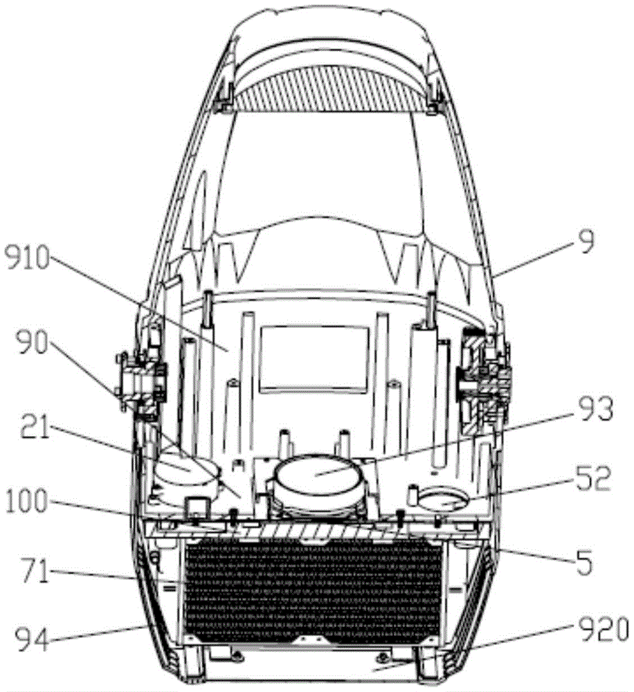
图1是一实施例的灯体剖视图;1 is a cross-sectional view of a lamp body according to an embodiment;
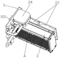
图2是一实施例的散热器结构图;2 is a structural diagram of a heat sink according to an embodiment;
图3是图2实施例的散热器爆炸图;Fig. 3 is the radiator exploded view of the embodiment of Fig. 2;
图4是一实施例的导热板结构图;4 is a structural diagram of a thermally conductive plate according to an embodiment;
图5是图3实施例中部分结构的爆炸图;Fig. 5 is the exploded view of the partial structure in the embodiment of Fig. 3;
图6是一实施例的换热盒与第二散热器结构图;6 is a structural diagram of a heat exchange box and a second radiator according to an embodiment;
图7是图6实施例的A部放大图;Fig. 7 is the enlarged view of A part of the embodiment of Fig. 6;
图8是一实施例的灯具结构图;FIG. 8 is a structural diagram of a lamp according to an embodiment;
图9是图8实施例的灯具剖视图。FIG. 9 is a cross-sectional view of the lamp of the embodiment of FIG. 8 .
附图标记:100-换热盒,111-第一导流入口,112-第二导流出口,113-第一导通槽,114-第二导通槽,115-液槽,121-进液口,122-排液口,123-沟槽;21-第一风机,22-第二风机,23-第三风机,24-第二泵;3-第一散热排,30-第二散热排,31-扁管,32-鳍片,33-通气孔;4-灯臂,400-第三腔体,41-套管;5-导热板, 51-第一导流出口,52-第二导流入口,53-翅片;8-灯座,800-第四腔体,9-灯体, 90-隔板,910-第一腔体,920-第二腔体,93-光源,94-通风口。Reference numerals: 100-heat exchange box, 111-first diversion inlet, 112-second diversion outlet, 113-first conduction groove, 114-second conduction groove, 115-liquid tank, 121-inlet Liquid port, 122-liquid outlet, 123-groove; 21-first fan, 22-second fan, 23-third fan, 24-second pump; 3-first heat dissipation row, 30-second heat dissipation Row, 31-flat tube, 32-fin, 33-vent hole; 4-lamp arm, 400-third cavity, 41-sleeve; 5-conducting plate, 51-first diversion outlet, 52-th Two guide inlets, 53-fin; 8-lamp base, 800-fourth cavity, 9-lamp body, 90-partition, 910-first cavity, 920-second cavity, 93-light source, 94 - Vents.
具体实施方式Detailed ways
为了使本实用新型的目的、技术方案及优点更加清楚明白,以下结合附图及实施例,对本实用新型进行进一步详细说明。应当理解,此处所描述的具体实施例仅仅用以解释本实用新型,并不用于限定本实用新型。In order to make the purpose, technical solutions and advantages of the present utility model more clearly understood, the present utility model will be further described in detail below with reference to the accompanying drawings and embodiments. It should be understood that the specific embodiments described herein are only used to explain the present invention, and are not intended to limit the present invention.
本实用新型的术语涉及:方向,如上、下、左、右、前、后,优先级按图示方向、上下文情景、附图视角为基准。顺序,如第一、第二,仅用于区别技术特征,并非隐含具体数量或先后关系。和/或,如甲和/或乙,表示存在甲和乙、甲、乙三种实施方式。The terms of the present invention relate to: direction, such as up, down, left, right, front, back, and the priority is based on the direction of the illustration, the context, and the perspective of the drawing. The order, such as the first and the second, is only used to distinguish technical features, and does not imply a specific quantity or sequence relationship. And/or, such as A and/or B, means that there are three embodiments of A and B, A and B.
此外,下面所描述的本实用新型各实施方式并不局限于各段落直观记载的技术方案,各方面、各段落、段落中的实施例、实施例中的技术特征只要彼此之间未构成冲突就可以任意组合,组合后的技术方案仍属于本实用新型的记载范围之内。In addition, the various embodiments of the present invention described below are not limited to the technical solutions directly recorded in each paragraph, and each aspect, each paragraph, the embodiment in the paragraph, and the technical features in the embodiment are not in conflict with each other. It can be combined arbitrarily, and the combined technical solutions still fall within the scope of the description of the present invention.
第一方面first
实施方式一Embodiment 1
如图1~9所示,一种灯体,包括壳体、光源和散热器。As shown in Figures 1-9, a lamp body includes a casing, a light source and a heat sink.
壳体包括密闭设置的第一腔体。The housing includes a sealed first cavity.
光源设于第一腔体内。The light source is arranged in the first cavity.
散热器包括第一散热器和第二散热器。The heat sink includes a first heat sink and a second heat sink.
第一散热器包括冷却介质,冷却介质是气体和/或第一冷却液,冷却介质在第一腔体内与第一腔体外循环流动以用于热交换。The first radiator includes a cooling medium, the cooling medium is a gas and/or a first cooling liquid, and the cooling medium circulates inside and outside the first cavity for heat exchange.
第二散热器设于第一腔体外,第二散热器与光源的导热面连接以用于热交换。The second radiator is disposed outside the first cavity, and the second radiator is connected to the heat conducting surface of the light source for heat exchange.
由于光源93设于密闭设置的第一腔体910内,可防止被水损毁。光源产生的热量,部分热量先传递至冷却介质,然后通过自然对流或强迫对流促使冷却介质在第一腔体内与第一腔体外循环流动以进行散热;部分热量通过光源的导热面热传递至第一腔体外,使第二散热器的热量不会热传递至第一腔体910内而直接排出至第一腔体910外。Since the
可选的,光源93的导热面为光源的侧面和/或光源的底面。此外,光源的出光面也会散发热量并逸出至第一腔体910内,但基于出光目的而不作为导热面。Optionally, the heat conduction surface of the
可选的,第一腔体910内设有处理灯光效果的发热器件,发热器件包括图案切割模块、CMY混色模块、调焦模块、放大模块、染色模块、图案分割模块等至少一种。由于上述模块由电机驱动和PCB板控制,因此电机与PCB板也会产生热量,散发至第一腔体910内的热量主要来源于光源93、电机、PCB板和零件摩擦。Optionally, the
可选的,第二散热器与光源93的导热面连接。在一些实施例中,所述连接可以是非接触式包围光源的侧面和/或非接触式包围光源的底面;在另一些实施例中,所述连接可以是贴合光源的侧面和/或贴合光源的底面。在又一些实施例中,所述连接可以是贴合光源的底面,且同时非接触式包围光源的侧面或贴合光源的侧面。Optionally, the second heat sink is connected to the heat conducting surface of the
可选的,光源93设于第一腔体910内包括以下几种情形:在一些实施例中,光源93设于第一腔体910内与第一腔体910外的交界以使光源93的导热面暴露于第一腔体910外;由此,第二散热器则无需伸入第一腔体910内连接光源 93,同时使光源93的导热面与第二散热器两者的热量不会热传递至第一腔体 910内而直接排出至第一腔体910外。在另一些实施例中,如图1所示,光源 93设于第一腔体910内与第一腔体910外的交界以使光源93的侧面置于第一腔体910内而光源93的底面暴露于第一腔体910外;由此,第二散热器则无需伸入第一腔体910内连接光源,光源93也不会横跨第一腔体910内与第二腔体 910外,使得结构紧凑,更为方便地将光源93的底面与第二散热器贴合安装以便于第一腔体910的密封,同时使第二散热器的热量不会热传递至第一腔体910 内而直接排出至第一腔体910外。Optionally, the arrangement of the
在一些实施例中,光源93设于第一腔体910内与第一腔体910外的交界以使光源93的导热面暴露于第一腔体910外,第二散热器可伸入第一腔体910 内吸收光源93的出光面散发的热量。在另一些实施例中,光源93设于第一腔体910内与第一腔体910外的交界以使光源93的侧面置于第一腔体910内而光源93的底面暴露于第一腔体910外,第二散热器可伸入第一腔体910内与光源 93的侧面贴合或非接触式包围。在又一些实施例中,光源93设于第一腔体910 内且使光源93的导热面完全置于第一腔体910内,第二散热器可伸入第一腔体 910内与光源的导热面连接。In some embodiments, the
实施方式二
可选的,所述第一散热器还包括循环驱动件和第一散热排,第一散热排设于第一腔体外以用于热交换,第一腔体与第一散热排相通,循环驱动件促使冷却介质在第一腔体内、第一散热排之间循环流动;所述循环驱动件是第一风机或第一泵。Optionally, the first radiator further includes a circulating drive member and a first heat dissipation row, the first heat dissipation row is arranged outside the first cavity for heat exchange, the first cavity is communicated with the first heat dissipation row, and the circulation drive is performed. The component promotes the circulating flow of the cooling medium in the first cavity and between the first heat sinks; the circulating driving component is the first fan or the first pump.
在一些实施例中,如图1~2所示,所述第一散热器还包括第一风机21和第一散热排3,第一散热排3设于第一腔体910外以用于热交换,第一腔体910 与第一散热排3相通,第一风机21促使气体在第一腔体910内、第一散热排3 之间循环流动。采用气体作为冷却介质,气体能够与发热零部件密切接触以便于充分吸热,第一风机21启动后在第一散热排3形成负压腔而在第一腔体910 内形成正压腔以驱动气体流动,气体无需额外包装即可进入冷却循环,轻便安全。In some embodiments, as shown in FIGS. 1 to 2 , the first heat sink further includes a
在一些实施例中,所述第一散热器还包括第一泵和第一散热排,第一散热排设于第一腔体外以用于热交换,第一腔体与第一散热排相通,第一泵促使第一冷却液在第一腔体内、第一散热排之间循环流动。进一步的,第一冷却液通过铜、铝等导热管包装以流通于第一腔体内,用于对腔内气体或光源的导热面进行吸热。采用液态流体作为冷却介质,固体能够对发热模块快速吸热,流动的第一冷却液能够将热量快速吸收和传递,传热效果佳。In some embodiments, the first heat sink further includes a first pump and a first heat sink, the first heat sink is provided outside the first cavity for heat exchange, and the first cavity communicates with the first heat sink, The first pump promotes the circulating flow of the first cooling liquid in the first cavity and between the first heat sinks. Further, the first cooling liquid is packaged by a heat conducting pipe such as copper or aluminum to circulate in the first cavity, so as to absorb heat from the gas in the cavity or the heat conducting surface of the light source. Using liquid fluid as the cooling medium, the solid can quickly absorb heat to the heating module, and the flowing first cooling liquid can quickly absorb and transfer the heat, and the heat transfer effect is good.
实施方式三
可选的,所述散热器还包括与光源导热面连接的换热盒100,换热盒100 设有导通槽,导通槽分别跟第一散热排3与第一腔体910相通,循环驱动件促使冷却介质在第一腔体910内、导通槽、第一散热排3之间循环流动。光源93 的导热面将热量传递至换热盒100,热量传导至导通槽,冷却介质在导通槽流动并不断吸收热量,循环驱动件促使冷却介质在第一腔体910内、导通槽、第一散热排3之间循环流动,热量跟随冷却介质进入第一腔体910内进行吸热并流入第一散热排3进行放热,放热后的冷却介质返回导通槽进入下一轮冷却循环。Optionally, the radiator further includes a
在一些实施例中,如图3、图5所示,导通槽包括第一导通槽113和第二导通槽114,第一导通槽113设有第一导流入口111,第二导通槽114设有第一导流出口112,第一导流入口111分别跟第一散热排3与第一腔体910相通,第一导流出口112分别跟第一散热排3与第一腔体910相通。通过缩小导流出入口,便于第一腔体与第一散热排3的密封连接。In some embodiments, as shown in FIGS. 3 and 5 , the conducting groove includes a
在一些实施例中,如图1、图3、图5所示,冷却介质从第一散热排3流出,然后依次经过第一导流入口111、第一导通槽113、第一腔体910内、第二导通槽114、第一导流出口112,最后流回第一散热排3,通过单循环路径完成一轮冷却循环。在另一些实施例中,第一导通槽113设有第一导流入口和第一导流出口,第二导通槽114也设有第一导流入口和第一导流出口,第一冷却液从第一散热排3流出,然后依次经过第一导通槽113的第一导流入口、第一导通槽 113、第一腔体910内、第一导通槽113及其第一导流出口,最后流回第一散热排3;气流从第一散热排3流出,然后依次经过第二导通槽114的第一导流入口、第二导通槽114、第一腔体910内、第二导通槽114及其第一导流出口,最后流回第一散热排3;通过双循环路径完成一轮冷却循环。In some embodiments, as shown in FIG. 1 , FIG. 3 , and FIG. 5 , the cooling medium flows out from the first
实施方式四
可选的,所述散热器还包括与光源导热面连接的换热盒,换热盒设有液槽,第二散热器包括第二泵、第二冷却液和第二散热排,第二散热排设于第一腔体外以用于热交换,第二散热排与液槽相通,第二泵促使第二冷却液在液槽与第二散热排之间循环流动。Optionally, the radiator further includes a heat exchange box connected to the heat conduction surface of the light source, the heat exchange box is provided with a liquid tank, the second radiator includes a second pump, a second cooling liquid and a second heat dissipation row, and the second heat dissipation The row is arranged outside the first cavity for heat exchange, the second heat dissipation row is communicated with the liquid tank, and the second pump promotes the circulation of the second cooling liquid between the liquid tank and the second heat dissipation row.
在实施方式一的基础上,所述散热器还包括与光源93连接的换热盒100,换热盒100设有液槽115,第二散热器包括第二泵24、第二冷却液和第二散热排30,第二散热排30设于第一腔体910外以用于热交换,第二散热排30与液槽115相通,第二泵24促使第二冷却液在液槽115与第二散热排30之间循环流动。光源的导热面将热量传递至换热盒100的第二冷却液,第二冷却液在液槽115流动并不断吸收热量,第二泵24促使第二冷却液在液槽与第二散热排 30之间循环流动,热量跟随第二冷却液流入第二散热排30进行放热,放热后的第二冷却液返回液槽115进入下一轮冷却循环,通过液冷循环以提高热传递效率。On the basis of Embodiment 1, the radiator further includes a
在实施方式二的基础上,所述散热器还包括与光源93连接的换热盒100,换热盒100设有液槽115,第二散热器包括第二泵24、第二冷却液和第二散热排30,第二散热排30设于第一腔体910外以用于热交换,第二散热排30与液槽115相通,第二泵24促使第二冷却液在液槽115与第二散热排30之间循环流动。通过双重冷却循环以提高热传递效率,能够将第一腔体内的热量快速地散发至第一腔体外。On the basis of
在实施方式三的基础上,所述散热器还包括与光源导热面连接的换热盒 100,换热盒设有液槽115,第二散热器包括第二泵24、第二冷却液和第二散热排30,第二散热排30设于第一腔体910外以用于热交换,第二散热排30与液槽115相通,第二泵24促使第二冷却液在液槽115与第二散热排30之间循环流动。通过换热盒100的液槽115与导通槽,光源93的导热面产生的热量,快速传递至换热盒100的液槽115与导通槽中,液槽115的第二冷却液能够快速吸收大部分热量再进入第二散热器的冷却循环,少部分热量传导至导通槽再进入第一散热器的冷却循环,充分带走由光源93的导热面散发的热量。On the basis of
在一些实施例中,第一散热排3和第二散热排30间隔设置,两者一并固定设于换热盒100上,使得结构紧凑,减少占用空间。In some embodiments, the
在一些实施例中,第二冷却液的循环方向可以是第二泵24从液槽115抽走第二冷却液或第二泵24往液槽115通入第二冷却液。In some embodiments, the circulation direction of the second cooling liquid may be that the
在一些实施例中,第一散热器和第二散热器中的冷却液均可以是水。在另一些实施例中,第一散热器和第二散热器中的冷却液均可以是防冻液。In some embodiments, the coolant in both the first radiator and the second radiator may be water. In other embodiments, the coolant in both the first radiator and the second radiator may be antifreeze.
实施方式五
可选的,所述第一散热排和/或所述第二散热排设有鳍片和扁管,鳍片呈波纹形,扁管具有微通道,鳍片与扁管层叠设置以使鳍片的波峰接触扁管。通过改变过流截面形状、形成湍流和增加换热面积以提高热传递效率。Optionally, the first heat sink and/or the second heat sink are provided with fins and flat tubes, the fins are corrugated, the flat tubes have microchannels, and the fins and the flat tubes are stacked to make the fins The crest of the wave contacts the flat tube. The heat transfer efficiency is improved by changing the shape of the flow cross section, forming turbulent flow and increasing the heat exchange area.
在一些实施例中,所述第一散热排3设有鳍片32和扁管31,鳍片32呈波纹形,扁管31具有微通道,鳍片32与扁管31层叠设置以使鳍片32的波峰接触扁管31。在另一些实施例中,所述第二散热排30设有鳍片32和扁管31,鳍片32呈波纹形,扁管31具有微通道,鳍片32与扁管31层叠设置以使鳍片32 的波峰接触扁管31。在又一些实施例中,所述第一散热排3和所述第二散热排 30均设有鳍片32和扁管31,鳍片32呈波纹形,扁管31具有微通道,鳍片32 与扁管31层叠设置以使鳍片32的波峰接触扁管31。In some embodiments, the
在一些实施例中,所述鳍片32、扁管31的材质均为铝,能够保持良好的散热性能且使结构更轻盈。在另一些实施例中,所述鳍片32、扁管31的材质可以是铝、金、铜、银等其中一种或多种。In some embodiments, the
实施方式六Embodiment 6
可选的,所述散热器还包括第二风机,第二风机具有防水结构以对第一散热排和/或第二散热排进行强迫对流。通过层层关联的热传递结构,能够高效地将热量散发至第一腔体外。Optionally, the radiator further includes a second fan, and the second fan has a waterproof structure to perform forced convection on the first heat dissipation row and/or the second heat dissipation row. Through the layer-by-layer associated heat transfer structure, the heat can be efficiently dissipated to the outside of the first cavity.
在一些实施例中,由于鳍片32与扁管31层叠设置以使鳍片32的波峰接触扁管31,从而在波纹处围成笔直的通气孔33,鳍片32与扁管31散发的热量传递至通气孔33内的气体,第二风机22的出风口朝向通气孔33送风以使通气孔 33内强迫对流。在另一些实施例中,与前述实施例相比所不同的是:第二风机 22的入风口朝向通气孔33抽风以使通气孔33内强迫对流。在笔直的通气孔33 中,气体可快速流通,波纹形鳍片增大了换热面积,可不断吹走或抽走通气孔内的吸热气体,在散热排中,通过液态流体与气态流体交错冷却或液态流体与液态流体交错冷却,两者相辅相成大大提高了热传递效率,能够高效地将热量散发至第一腔体910外。In some embodiments, since the
在实施方式一、二或实施方式一、二、三的基础上,所述散热器还包括第二风机22,第二风机22具有防水结构以对第一散热排3进行强迫对流,从而提高第一散热器的热交换效率。On the basis of
在实施方式一、四的基础上,所述散热器还包括第二风机22,第二风机22 具有防水结构以对第二散热排30进行强迫对流,从而提高第二散热器的热交换效率。On the basis of
在实施方式一、二、四或实施方式一、二、三、四的基础上,所述散热器还包括第二风机22,第二风机具有防水结构以对第一散热排3和第二散热排30 进行强迫对流,从而提高第一散热器与第二散热器的热交换效率。进一步的,如图2~3所示,第二风机的工作位置或作用存在几种情形:在一些实施例中,第二风机22分别设于第一散热排3的外侧和第二散热排30的外侧分别对各散热排送风;在另一些实施例中,第二风机分别设于第一散热排3的内侧和第二散热排30的内侧分别对各散热排送风;在又一些实施例中,第二风机设于第一散热排3与第二散热排30的中间区域以对其中一个散热排抽风并对另一个散热排送风。此外,第二风机22也可对第一散热排3与第二散热排30的中间区域进行抽风或送风。On the basis of
在一些实施例中,所述强迫对流是对第一散热排3或第二散热排30单侧抽风、单侧送风、在单侧既抽风又送风、双侧抽风、双侧送风、在一侧抽风且另一侧送风。在另一些实施例中,所述强迫对流是对第一散热排3和第二散热排 30单侧抽风、单侧送风、在单侧既抽风又送风、双侧抽风、双侧送风、在一侧抽风且另一侧送风。In some embodiments, the forced convection is to draw air from one side of the
实施方式七Embodiment 7
可选的,所述散热器还包括导热板,导热板的一面与光源的导热面连接以用于热交换,导热板的另一面跟换热盒的液槽密封连接。可选的,所述散热器还包括导热板,导热板的一面与光源的导热面连接以用于热交换,导热板的另一面跟换热盒的液槽与导通槽密封连接且导热板开设通孔以使导通槽与第一腔体相通。Optionally, the radiator further includes a heat-conducting plate, one side of the heat-conducting plate is connected to the heat-conducting surface of the light source for heat exchange, and the other side of the heat-conducting plate is hermetically connected to the liquid tank of the heat exchange box. Optionally, the radiator further includes a heat-conducting plate, one side of the heat-conducting plate is connected to the heat-conducting surface of the light source for heat exchange, and the other side of the heat-conducting plate is sealedly connected to the liquid groove and conduction groove of the heat exchange box, and the heat-conducting plate is A through hole is opened so that the conducting groove communicates with the first cavity.
在一些实施例中,所述导热板5一体凸设翅片53,翅片间隔设置形成间隙,间隙用于流通第二冷却液,导热板的一面与光源的导热面连接后使翅片53置于液槽115,通过增大换热面积以提高热传递效率。在另一些实施例中,与前述实施例相比所不同的是:所述液槽115设有翅片53,翅片一端抵接导热板5。In some embodiments, the heat-conducting
在一些实施例中,所述液槽115设有进液口121、排液口122和沟槽123,第二散热排30分别跟液槽115的进液口121和排液口122连通,第二泵24 促使第二冷却液从进液口121进入液槽115,第二冷却液沿一侧的沟槽123流过所述间隙,再沿另一侧的沟槽123流进排液口122,以使第二冷却液在液槽 115和第二散热排30之间循环流动,从而方便第二冷却液流通于翅片间的间隙以带走热量。In some embodiments, the
在一些实施例中,如图3所示,导热板开设通孔,通孔具有第一导流出口 51和第一导流入口52,第一导流出口51和第一导流入口52为大通孔,大通孔的内径不超过第一风机的出入口的外径,大通孔与第一风机的出入口相通,减少阻力以便于气体循环流动。在另一些实施例中,如图4所示,导热板5具有第一风口51和第二风口52,第一导流出口51和第一导流入口52为微形孔集合,微形孔集合与包装第一冷却液的导热管相通,一方面便于微形孔集合与导热管的密封,另一方面,增加导热管数量来增大换热面积以便于充分吸收第一腔体内的热量与换热盒的热量。此外,微形孔集合也适用于气体循环,便于增大微形孔集合与气体的接触面积,另一方面,在微形孔处容易形成湍流,传热效果更佳。In some embodiments, as shown in FIG. 3 , the heat conducting plate is provided with through holes, the through holes have a
所述导热板5是相变导热板或非相变导热板。在一些实施例中,所述导热板5是相变导热板。在另一些实施例中,所述导热板5是非相变导热板。The heat-conducting
在一些实施例中,所述导热板5与隔板90密封连接,对应第一导流出口 51、第一导流入口52的隔板90表面设有开孔,第一风机21安装于隔板90表面的开孔对应处,第一风机21无需与导热板5直接连接,避免导热板5的高温损毁第一风机21以及破坏气密性。In some embodiments, the heat-conducting
实施方式八
可选的,壳体还包括开放设置的第二腔体,第一散热排和/或第二散热排设于第二腔体以用于热交换。Optionally, the housing further includes an open second cavity, and the first heat sink and/or the second heat sink are arranged in the second cavity for heat exchange.
在一些实施例中,实施方式一至七中所述的第一腔体910外为第二腔体920。In some embodiments, the
在一些实施例中,第二腔体920在前后左右四个方向设有通风口94,便于第二腔体与灯体外相通。In some embodiments, the
在一些实施例中,如图1~2所示,第一风机21设于第一腔体910内,第一风机21的入风口与导热板5的第一导流出口51相通,第一散热排3和第二散热器均设于第二腔体920内,使得结构紧凑,避免第一风机占用第二腔体的空间而扩大第二腔体920的体积。In some embodiments, as shown in FIGS. 1 to 2 , the
在一些实施例中,灯体在水下工作时,壳体可阻挡杂物进入第二腔体920 损坏第一散热排3和第二散热器,也避免杂物覆盖第一散热排3与第二散热排 30影响散热,起到保护作用。在另一些实施例中,灯体在水上工作时,壳体的第二腔体920起到美观和保护作用。In some embodiments, when the lamp body works underwater, the housing can prevent foreign matter from entering the
第二方面the second aspect
实施方式九Embodiment nine
一种灯具,包括第一方面任意组合的灯体9。A lamp includes
在一些实施例中,所述灯具可以是面板灯、摇头灯、追光灯、车展灯、筒灯、路灯、探照灯等。In some embodiments, the light fixture may be a panel light, moving head light, follow spot light, car show light, down light, street light, search light and the like.
第三方面the third aspect
实施方式十Embodiment ten
如图1~图9所示,一种摇头灯具,包括灯体9、灯臂4、灯座8和散热器,灯体9包括壳体和光源93,壳体包括密闭设置的第一腔体910,光源93设于第一腔体内;灯臂4具有开放设置的第三腔体400,灯臂4与灯体9转动连接;灯座8具有密闭设置的第四腔体800,灯座8与灯臂4转动连接;散热器包括第一散热器和第二散热器;第一散热器包括冷却介质,冷却介质是气体或第一冷却液,冷却介质在第一腔体内与第一腔体外循环流动以用于热交换;第二散热器设于第一腔体外,第二散热器与光源的导热面连接以用于热交换。As shown in Figures 1 to 9, a moving head lamp includes a
得益于灯体9结构紧凑、轻巧、散热效率高的特性,灯体9、灯臂4、灯座8既无需额外扩大体积,也不会增加重量,灯臂4、连接灯臂与灯体的转轴组件也无需相应地提高承重能力、刚度、强度以维持稳定性,从而使得灯具结构紧凑、轻巧。Thanks to the characteristics of the
在一些实施例中,第三方面的灯体9包括第一方面任意组合所述的灯体9。In some embodiments, the
在另一些实施例中,第三方面的灯体9引用第一方面任意组合所述的灯体 9,不同之处在于:第一散热排3的安装位置和/或第二散热排30的安装位置,可见实施方式十一至十二部分。In other embodiments, the
在一些实施例中,所述灯臂4与灯体9通过第一转轴组件转动连接,第一转轴驱动器设于第一腔体910,第一转轴驱动器与第一转轴组件连接以用于驱动灯体9相对于灯臂4转动;灯座8与灯臂4通过第二转轴组件转动连接,第二转轴驱动器设于第四腔体800,第二转轴驱动器与第二转轴组件连接以用于驱动灯臂4相对于灯座8转动。由于第一腔体910和第四腔体800均是密闭设置的,即使第三腔体400开放设置也不会影响灯具的正常工作,使得摇头灯具的结构紧凑、轻便。In some embodiments, the
在一些实施例中,第一转轴驱动器与第二转轴驱动器均设有防水结构,第一转轴驱动器、第二转轴驱动器设于开放设置的第三腔体400。由于第一转轴驱动器与第二转轴驱动器均设有防水结构,即使第三腔体400开放设置也不会影响灯具的正常工作。在一些对比例中,由于第三腔体400是密闭设置的,第一转轴驱动器、第二转轴驱动器设于密闭设置的第三腔体400,因此需要在灯臂4增设散热模块,从而导致灯臂4的体积和重量增加,从而使得灯具的体积和重量增加。In some embodiments, the first rotating shaft driver and the second rotating shaft driver are both provided with a waterproof structure, and the first rotating shaft driver and the second rotating shaft driver are disposed in the
在一些实施例中,第一转轴组件的轴向中心和第二转轴组件的轴向中心中空设置和/或径向开孔,第一腔体910和/或第二腔体920跟第三腔体400可通过第一转轴组件相通;第三腔体400跟第四腔体800可通过第二转轴组件相通;第一腔体910和/或第二腔体920跟第四腔体800可通过第一转轴组件与第二转轴组件相通。In some embodiments, the axial center of the first rotating shaft assembly and the axial center of the second rotating shaft assembly are hollow and/or radially open, the
进一步的,各腔体通过套管41相通,套管41穿过第一转轴组件和/或第二转轴组件的轴向中心以用于走线。在一些实施例中,套管41穿过第一转轴组件和/或第二转轴组件的轴向中心以用于流通冷却介质。在另一些实施例中,套管 41穿过第一转轴组件和/或第二转轴组件的轴向中心以用于走线和流通冷却介质。Further, the cavities communicate with each other through a
实施方式十一Embodiment eleven
可选的,所述第一散热器的第一散热排设于第二腔体以用于热交换,所述第二散热器的第二散热排设于第三腔体或第四腔体以用于热交换。Optionally, the first heat sink of the first heat sink is arranged in the second cavity for heat exchange, and the second heat sink of the second heat sink is arranged in the third cavity or the fourth cavity for heat exchange. for heat exchange.
在一些实施例中,所述第一散热器还包括循环驱动件和第一散热排3,第一散热排3设于第二腔体920以用于热交换,第一腔体910与第一散热排3相通,循环驱动件促使冷却介质在第一腔体910内、第一散热排3之间循环流动;所述循环驱动件是第一风机21或第一泵。第二散热器包括第二泵24、第二冷却液和第二散热排30,第二散热排30设于第三腔体400以用于热交换,第二散热排30与液槽115相通,第二泵24促使第二冷却液在液槽115与第二散热排30之间循环流动。可选的,循环驱动件设于第一腔体910或第二腔体920。可选的,第二泵24可设于第一腔体910、第二腔体920、第三腔体400、第四腔体800任一腔体。在另一些实施例中,与前述实施例相比所不同的是:第二散热排30设于第四腔体800以用于热交换。In some embodiments, the first heat sink further includes a circulating driving member and a first
在一些实施例中,由于第四腔体800是密闭设置的,为提高散热效率,散热器还包括第三风机23,第三风机23设于灯臂4的第三腔体400,第三风机 23具有防水结构以对灯座8的上端面进行强迫对流。In some embodiments, since the
实施方式十二Embodiment 12
可选的,所述第一散热器的第一散热排设于第三腔体以用于热交换,所述第二散热器的第二散热排设于第二腔体、第三腔体、第四腔体任一腔体以用于热交换。Optionally, the first heat sink of the first heat sink is arranged in the third cavity for heat exchange, and the second heat sink of the second heat sink is arranged in the second cavity, the third cavity, Any of the fourth cavities is used for heat exchange.
在一些实施例中,所述第一散热器还包括循环驱动件和第一散热排3,第一散热排3设于第三腔体400以用于热交换,第一腔体910与第一散热排3相通,循环驱动件促使冷却介质在第一腔体910内、第一散热排3之间循环流动;所述循环驱动件是第一风机21或第一泵。第二散热器包括第二泵24、第二冷却液和第二散热排30,第二散热排30设于第二腔体920以用于热交换,第二散热排30与液槽115相通,第二泵24促使第二冷却液在液槽115与第二散热排30之间循环流动。可选的,循环驱动件设于第一腔体910或第三腔体400。可选的,第二泵24可设于第一腔体910、第二腔体920、第三腔体400、第四腔体800任一腔体。在另一些实施例中,与前述实施例相比所不同的是:第二散热排30设于第三腔体400或第四腔体800以用于热交换,此时,第二腔体 920只需容置换热盒,可大幅度缩减第二腔体920的体积或直接缺省第二腔体 920,进而大幅度缩减灯体的体积和重量;在其他一些实施例中,第二腔体920 可无需开设通风口94,则第一腔体910与第二腔体920也可无需隔断设置,第一腔体910可无需密封设置,从而简化安装结构,使得结构紧凑、轻巧。In some embodiments, the first heat sink further includes a circulating driving member and a first
第四方面Fourth aspect
实施方式十三Embodiment thirteen
一种灯体散热方法,包括:光源将热量热传递至密闭设置的第一腔体内,第一腔体内的热量通过冷却介质从第一腔体内热传递至第一腔体外,光源的导热面将热量热传递至第一腔体外;其中,冷却介质先在第一腔体内进行吸热,吸热后的冷却介质再从第一腔体内流动至第一腔体外,吸热后的冷却介质在第一腔体外进行放热,放热后的冷却介质从第一腔体外返回第一腔体内进入下一轮吸热,如此往复循环。A method for dissipating heat from a lamp body, comprising: a light source transfers heat to a sealed first cavity, the heat in the first cavity is transferred from the inside of the first cavity to the outside of the first cavity through a cooling medium, and the heat conduction surface of the light source The heat is transferred to the outside of the first cavity; wherein, the cooling medium first absorbs heat in the first cavity, the cooling medium after heat absorption flows from the first cavity to the outside of the first cavity, and the cooling medium after heat absorption is in the first cavity. Heat is released outside a cavity, and the cooling medium after heat release is returned from outside the first cavity to the first cavity to enter the next round of heat absorption, and so on and so forth.
该灯体散热方法通过两套冷却循环路径进行散热,一方面,将第一腔体910 内与第一腔体910外分隔开来,在第一腔体910内进行吸热,转移至第一腔体 910外进行放热,在不同的独立空间进行吸热与放热,热量互不干涉,能够快速有效地将热量传递出灯体9外;另一方面,光源93的导热面直接将热量传递出灯体9外,缩减散热路径以提高散热效率。The heat dissipation method of the lamp body dissipates heat through two sets of cooling circulation paths. A
在一些实施例中,一种灯体散热方法,包括:光源93将热量热传递至密闭设置的第一腔体910内,第一腔体910内的热量通过冷却介质从第一腔体910 内热传递至开放设置的第二腔体920,光源93的导热面将热量热传递至第二腔体920;其中,冷却介质先在第一腔体910内进行吸热,吸热后的冷却介质再从第一腔体910内流动至第二腔体920,吸热后的冷却介质在第二腔体920进行放热,放热后的冷却介质从第二腔体920返回第一腔体910内进入下一轮吸热,如此往复循环。In some embodiments, a method for dissipating heat from a lamp body includes: the
在一些实施例中,一种灯具散热方法,包括:光源93将热量热传递至密闭设置的第一腔体910内,第一腔体910内的热量通过冷却介质从第一腔体910 内热传递至开放设置的第二腔体920,光源93的导热面将热量热传递至第三腔体400或第四腔体800;其中,冷却介质先在第一腔体910内进行吸热,吸热后的冷却介质再从第一腔体910内流动至第二腔体920,吸热后的冷却介质在第二腔体920进行放热,放热后的冷却介质从第二腔体920返回第一腔体910 内进入下一轮吸热,如此往复循环。In some embodiments, a method for dissipating heat from a lamp includes: the
在一些实施例中,一种灯具散热方法,包括:光源93将热量热传递至密闭设置的第一腔体910内,第一腔体910内的热量通过冷却介质从第一腔体910 内热传递至开放设置的第三腔体400,光源93的导热面将热量热传递至第二腔体920、第三腔体400、第四腔体800任一腔体;其中,冷却介质先在第一腔体 910内进行吸热,吸热后的冷却介质再从第一腔体910内流动至第二腔体920,吸热后的冷却介质在第二腔体920进行放热,放热后的冷却介质从第二腔体920 返回第一腔体910内进入下一轮吸热,如此往复循环。In some embodiments, a method for dissipating heat from a lamp includes: the
在一些实施例中,所述灯体散热方法、灯具散热方法可应用第一方面至第三方面任意组合的构造。In some embodiments, any combination of the first aspect to the third aspect can be applied to the method for dissipating heat from a lamp body and a method for dissipating heat from a lamp.
以上所述仅为本实用新型的较佳实施例而已,并不用以限制本实用新型,凡在本实用新型的精神和原则之内所作的任何修改、等同替换和改进等,均应包含在本实用新型的保护范围之内。The above are only preferred embodiments of the present invention, and are not intended to limit the present invention. Any modifications, equivalent replacements and improvements made within the spirit and principles of the present invention shall be included in the present invention. within the scope of protection of the utility model.
Claims (18)
Priority Applications (1)
| Application Number | Priority Date | Filing Date | Title |
|---|---|---|---|
| CN202220184400.2U CN216924079U (en) | 2022-01-24 | 2022-01-24 | Lamp body, lamp and head-shaking lamp |
Applications Claiming Priority (1)
| Application Number | Priority Date | Filing Date | Title |
|---|---|---|---|
| CN202220184400.2U CN216924079U (en) | 2022-01-24 | 2022-01-24 | Lamp body, lamp and head-shaking lamp |
Publications (1)
| Publication Number | Publication Date |
|---|---|
| CN216924079U true CN216924079U (en) | 2022-07-08 |
Family
ID=82263557
Family Applications (1)
| Application Number | Title | Priority Date | Filing Date |
|---|---|---|---|
| CN202220184400.2U Active CN216924079U (en) | 2022-01-24 | 2022-01-24 | Lamp body, lamp and head-shaking lamp |
Country Status (1)
| Country | Link |
|---|---|
| CN (1) | CN216924079U (en) |
Cited By (2)
| Publication number | Priority date | Publication date | Assignee | Title |
|---|---|---|---|---|
| CN115681920A (en) * | 2022-09-30 | 2023-02-03 | 湖南明和光电设备有限公司 | Waterproof heat dissipation module that fuses of lamp of shaking head |
| CN116518320A (en) * | 2022-01-24 | 2023-08-01 | 广州彩熠灯光股份有限公司 | Lamp body, lamp and lamp body heat dissipation method |
-
2022
- 2022-01-24 CN CN202220184400.2U patent/CN216924079U/en active Active
Cited By (3)
| Publication number | Priority date | Publication date | Assignee | Title |
|---|---|---|---|---|
| CN116518320A (en) * | 2022-01-24 | 2023-08-01 | 广州彩熠灯光股份有限公司 | Lamp body, lamp and lamp body heat dissipation method |
| CN116518320B (en) * | 2022-01-24 | 2025-10-14 | 广州彩熠科技股份有限公司 | Lamp body, lamp fixture and lamp body heat dissipation method |
| CN115681920A (en) * | 2022-09-30 | 2023-02-03 | 湖南明和光电设备有限公司 | Waterproof heat dissipation module that fuses of lamp of shaking head |
Similar Documents
| Publication | Publication Date | Title |
|---|---|---|
| CN213816733U (en) | Heat dissipation device and laser light source | |
| CN113448027B (en) | Optical module heat radiation structure, optical module and optical communication equipment | |
| US20060021737A1 (en) | Liquid cooling device | |
| CN214278869U (en) | Notebook computer cooling system | |
| CN110030629A (en) | A kind of air-conditioner outdoor unit and air conditioner | |
| CN220689013U (en) | Radiator module and photographic lamp | |
| CN212529295U (en) | Power assembly and electric automobile | |
| CN216981119U (en) | Laser heat abstractor | |
| CN222380085U (en) | Cooling circulation module and electronic device with same | |
| CN114449841A (en) | Radiator cabinet | |
| CN211745104U (en) | A cooling device for charging pile power supply | |
| CN119627594A (en) | An air-cooled fiber laser based on modular heat dissipation method | |
| TWM609012U (en) | Liquid cooling system | |
| CN103836386B (en) | Light fixture and its heat sink | |
| CN116518320B (en) | Lamp body, lamp fixture and lamp body heat dissipation method | |
| CN212901016U (en) | Lamp heat dissipation device and lamp | |
| CN213662271U (en) | cooling module | |
| CN211607189U (en) | Liquid cooling device with pumping structure | |
| CN216813919U (en) | Lamp set | |
| CN223859318U (en) | Circuit board with heat radiation structure | |
| CN207132762U (en) | Heat exchange structure of heat dissipation device | |
| CN216670331U (en) | Quick radiator of optical module | |
| CN212132321U (en) | High-power LED car light of samming board circulation heat dissipation | |
| CN222885033U (en) | Internal drive heat exchange radiator | |
| CN224218715U (en) | Liquid cooling heat radiation module and electronic expansion device with same |
Legal Events
| Date | Code | Title | Description |
|---|---|---|---|
| GR01 | Patent grant | ||
| GR01 | Patent grant | ||
| CP03 | Change of name, title or address | ||
| CP03 | Change of name, title or address |
Address after: No. 46 Ketai 1st Road, Guangzhou Private Science and Technology Park, Baiyun District, Guangzhou City, Guangdong Province, 510000 Patentee after: Guangzhou Caiyi Technology Co.,Ltd. Country or region after: China Address before: No. 46 Ketai 1st Road, Guangzhou Private Science and Technology Park, Baiyun District, Guangzhou City, Guangdong Province Patentee before: Guangzhou Colourful Lighting Co.,Ltd. Country or region before: China |