CN216894396U - Inclined shaft expands digs drilling and takes off integrative platform device of sediment - Google Patents
Inclined shaft expands digs drilling and takes off integrative platform device of sediment Download PDFInfo
- Publication number
- CN216894396U CN216894396U CN202123014297.1U CN202123014297U CN216894396U CN 216894396 U CN216894396 U CN 216894396U CN 202123014297 U CN202123014297 U CN 202123014297U CN 216894396 U CN216894396 U CN 216894396U
- Authority
- CN
- China
- Prior art keywords
- arm
- oil cylinder
- slag removing
- layer
- inclined shaft
- Prior art date
- Legal status (The legal status is an assumption and is not a legal conclusion. Google has not performed a legal analysis and makes no representation as to the accuracy of the status listed.)
- Active
Links
Images



Classifications
-
- Y—GENERAL TAGGING OF NEW TECHNOLOGICAL DEVELOPMENTS; GENERAL TAGGING OF CROSS-SECTIONAL TECHNOLOGIES SPANNING OVER SEVERAL SECTIONS OF THE IPC; TECHNICAL SUBJECTS COVERED BY FORMER USPC CROSS-REFERENCE ART COLLECTIONS [XRACs] AND DIGESTS
- Y02—TECHNOLOGIES OR APPLICATIONS FOR MITIGATION OR ADAPTATION AGAINST CLIMATE CHANGE
- Y02E—REDUCTION OF GREENHOUSE GAS [GHG] EMISSIONS, RELATED TO ENERGY GENERATION, TRANSMISSION OR DISTRIBUTION
- Y02E10/00—Energy generation through renewable energy sources
- Y02E10/20—Hydro energy
Landscapes
- Earth Drilling (AREA)
Abstract
The utility model relates to an inclined shaft expanding, digging, drilling and slag removing integrated platform device, and belongs to the technical field of hydraulic and hydroelectric engineering. The inclined shaft expanding, digging, drilling and slag removing integrated platform device comprises a frame assembly, a telescopic arm, a slag removing mechanism and a hydraulic system, wherein the telescopic arm is fixed on the frame assembly, the slag removing mechanism is installed at the end part of the telescopic arm, and the hydraulic system is respectively connected with the frame assembly, the telescopic arm and the slag removing mechanism. The telescopic arm is adopted to control the stretching of the slag removing mechanism, the swing mechanism is used to control the rotation of the slag removing mechanism, the slag removing mechanism can rotate 360 degrees around the rotating shaft during slag removing, the slag removing range covers the whole working surface, the slag removing is ensured not to have dead angles, the problems of low construction efficiency, high labor intensity of personnel, time and labor consumption, prominent safety problems and the like are solved, the modernization of inclined shaft construction equipment is realized, the manual work is replaced by machinery, the personnel using requirement of a high-risk working surface is reduced, the safety management risk is reduced, and the construction time is shortened.
Description
Technical Field
The utility model belongs to the technical field of hydraulic and hydroelectric engineering, and particularly relates to an inclined shaft expanding, digging, drilling and slag removing integrated platform device.
Background
In water conservancy and hydropower engineering, inclined shaft construction has always been a difficult point which must be faced in the construction process, and inclined shaft sections of hydropower engineering are usually longer, and the selected inclined angle is steeper, the construction space in a well is narrow, and the number of operation procedures is large. Influenced by the characteristics of construction and special environment, the inclined shaft construction safety risk of the hydraulic and hydroelectric engineering is high, personal casualty accidents are easy to happen, and the construction progress of the inclined shaft construction safety risk often becomes a key influence factor for judging whether the whole engineering is put into production on schedule or not.
At present, the main construction method of the domestic inclined shaft excavation comprises the steps of firstly adopting a raise boring machine to construct a guide shaft, then manually carrying out top-down expanding excavation molding by means of a lifting system, wherein the lifting system usually adopts a winch as traction equipment, a transport trolley and an expanding excavation trolley are arranged in the inclined shaft, the transport trolley is used for carrying personnel transportation during the inclined shaft construction period, and the expanding excavation trolley is used as a movable construction platform for excavating, forming holes and carrying out spray anchor support. During excavation blasting, part of the stone slag automatically slides downwards through the constructed guide shaft, but a large amount of stone slag remains on the working surface, workers are required to go down to the working face to remove the slag, the stone slag is removed into the guide shaft to slide downwards, and finally slag removal operation is completed. In the slag removing process, although workers take safety protection measures, unsafe factors in a well cannot be completely eliminated, inevitable deviation of guide shaft construction hole positions exists, the automatic slag sliding effect is poor after part of hole sections are blasted, the manual slag removing workload is large, the physical consumption of the workers is large, and dangerous factors are accumulated.
In recent years, the selection concept of young workers who newly participate in work is greatly changed, the number of workers who choose to engage in site construction of hydropower buildings is gradually reduced, and few workers who are willing to enter high-risk working environments such as inclined shafts and vertical shafts are required. With the strengthening of the aging trend of the population, the average age of workers in the inclined shaft one-line operation is continuously increased, and adverse effects are brought to the subsequent development of the hydropower construction.
Therefore, it is necessary to provide an inclined shaft expanding excavation drilling and slag removing integrated platform device, so that the modernization of inclined shaft construction equipment is realized, the manual work is replaced by machinery, the personnel demand of high-risk working faces is reduced, the safety management risk is reduced, and the construction time is shortened.
SUMMERY OF THE UTILITY MODEL
In order to overcome the problems that the construction safety risk of the inclined shaft of the hydraulic and hydroelectric engineering is high, personal casualty accidents are easy to happen, the construction progress is slow, the workload of manual slag raking is large, and the physical consumption of workers is large in the background technology under the influence of the characteristics of the construction and special environment, the utility model provides the inclined shaft expanded excavation, drilling and slag raking integrated platform device, which realizes the modernization of inclined shaft construction equipment, replaces the manual work with machinery, reduces the personnel using requirement of a high-risk working face, reduces the safety management risk and shortens the construction time.
In order to realize the purpose, the utility model is realized by the following technical scheme:
the utility model provides an inclined shaft expanding excavation drilling slag removing integrated platform device which comprises a frame assembly 1, a telescopic arm 2, a slag removing mechanism 3 and a hydraulic system, wherein the frame assembly comprises a frame, a telescopic arm and a slag removing mechanism; the telescopic arm 2 is fixed on the frame assembly 1, the slag raking mechanism 3 is installed at the end part of the telescopic arm 2, and the hydraulic system is respectively connected with the frame assembly 1, the telescopic arm 2 and the slag raking mechanism 3.
The frame assembly 1 comprises a frame mechanism 101, a wheel mechanism 102, a telescopic supporting leg hydraulic oil cylinder 103, an oil tank 104, a first layer platform mechanism 105, a second layer platform mechanism 106, a third layer platform mechanism 107, a steel wire rope hanging pulley component 108, a well lid mechanism 109 and a power system 110, wherein the frame mechanism 101 is matched with a deep inclined shaft and is obliquely arranged, the wheel mechanism 102 is arranged on the side, which is in contact with a track 4 arranged on the wall of the deep inclined shaft, of the frame assembly 1, the telescopic supporting leg hydraulic oil cylinders 103 are arranged at the top, at the bottom and on the periphery of the frame assembly 1, the first layer platform mechanism 105, the second layer platform mechanism 106 and the third layer platform mechanism 107 are arranged on the other side of the frame mechanism 101 from top to bottom, the steel wire rope hanging pulley component 108 is obliquely arranged on the first layer platform mechanism 105 and the second layer platform mechanism 106 respectively and is parallel to the frame mechanism 101, and the well lid mechanism 109 is hung at the bottom of the third layer platform mechanism 107, the power system 110 and the fuel tank 104 are mounted on the first deck platform mechanism 105.
The telescopic arm 2 comprises a first-section arm mechanism 201, a support rod 202, a vertical column assembly 203, a second-section arm mechanism 204 and a telescopic oil cylinder 205, wherein the first-section arm mechanism 201 is fixed at the top end of the vertical column assembly 203 through the support rod 202, the second-section arm mechanism 204 is in sliding connection with the end part of the first-section arm mechanism 201 through the telescopic oil cylinder 205, the bottom end of the vertical column assembly 203 is fixed on the frame mechanism 101, and the first-section arm mechanism 201 and the second-section arm mechanism 204 are respectively installed on the steel wire rope hanging pulley component 108 on the first-layer platform mechanism 105 and the second-layer platform mechanism 106 in a sliding mode.
The slag raking mechanism 3 comprises a rotary mechanism, a large arm 301, a large arm oil cylinder 302, a small arm 303, a small arm oil cylinder 304 and a bucket 305, wherein one end of the large arm 301 is mounted at the end part of the two-section arm mechanism 204 through the rotary mechanism, the small arm 303 is hinged at the other end of the large arm 301, the end part is connected with the side surface of the large arm 301 through the large arm oil cylinder 302, the other end of the small arm 303 is hinged with the bucket 305, and the bucket 305 is connected with the side surface of the small arm 303 through the small arm oil cylinder 304.
The telescopic support leg hydraulic oil cylinder 103, the telescopic oil cylinder 205, the large arm oil cylinder 302 and the small arm oil cylinder 304 are all connected with the oil tank 104, the hydraulic system and the power system 110.
Preferably, the slewing mechanism comprises a slewing reducer 306 and a slewing cylinder 307, the slewing reducer 306 and the slewing cylinder 307 are connected and mounted at the end of the two-joint arm mechanism 204, the slewing cylinder 307 is connected with the oil tank 104, the hydraulic system and the power system 110, and the slewing reducer 306 is connected with the power system 110.
Preferably, the outer sides of the first layer platform mechanism 105, the second layer platform mechanism 106 and the third layer platform mechanism 107 are all provided with guardrails 5.
Preferably, the swing mechanism drives the large arm 301 to rotate clockwise or counterclockwise by 360 °.
Preferably, the inclined shaft is internally provided with high-definition cameras at intervals, and the high-definition cameras are connected with the power system 110.
The utility model has the beneficial effects that:
the telescopic arm is adopted to control the stretching of the slag removing mechanism, the swing mechanism controls the rotation of the slag removing mechanism, the slag removing mechanism can rotate 360 degrees around the rotating shaft during slag removing, the slag removing range covers the whole working surface, the slag removing is ensured to have no dead angle, the problems of low construction efficiency, high labor intensity of personnel, time and labor consumption, prominent safety problem and the like are solved, the modernization of inclined shaft construction equipment is realized, the manual work is replaced by machinery, the personnel requirement of a high-risk working surface is reduced, the safety management risk is reduced, and the construction time is shortened.
Drawings
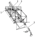
FIG. 1 is a schematic structural view of the present invention;
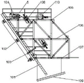
FIG. 2 is a schematic structural view of the frame assembly of the present invention;
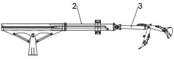
FIG. 3 is a schematic view of the construction of the telescopic arm of the present invention;
FIG. 4 is a schematic structural diagram of a slag raking mechanism of the present invention;
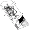
FIG. 5 is a schematic view of the use configuration of the present invention;
FIG. 6 is a schematic view of the connection structure of the telescopic arm in an extended state and a slag raking mechanism of the utility model;
FIG. 7 is a schematic view of the connection structure of the telescopic boom shortening state and the slag raking mechanism of the utility model.
In the figure, 1-a frame assembly, 2-a telescopic arm, 3-a slag raking mechanism, 4-a track, 5-a guardrail, 101-a frame mechanism, 102-a wheel mechanism, 103-a telescopic leg hydraulic oil cylinder, 104-an oil tank, 105-a first layer platform mechanism, 106-a second layer platform mechanism, 107-a third layer platform mechanism, 108-a steel wire rope hoisting pulley component, 109-a well cover mechanism, 110-a power system, 201-a section of arm mechanism, 202-a support rod, 203-an upright post assembly, 204-a second section of arm mechanism, 205-a telescopic oil cylinder, 301-a big arm, 302-a big arm oil cylinder, 303-a small arm, 304-a small arm oil cylinder, 305-an excavating bucket, 306-a rotary speed reducer and 307-a rotary oil cylinder.
Detailed Description
In order to make the objects, technical solutions and advantages of the present invention more apparent, preferred embodiments of the present invention will be described in detail below with reference to the accompanying drawings to facilitate understanding of the skilled person.
As shown in fig. 1-7, the inclined shaft expanding, digging, drilling and slag removing integrated platform device comprises a frame assembly 1, a telescopic arm 2, a slag removing mechanism 3 and a hydraulic system; the telescopic arm 2 is fixed on the frame assembly 1, the slag raking mechanism 3 is installed at the end part of the telescopic arm 2, and the hydraulic system is respectively connected with the frame assembly 1, the telescopic arm 2 and the slag raking mechanism 3.
The frame assembly 1 comprises a frame mechanism 101, a wheel mechanism 102, a telescopic leg hydraulic oil cylinder 103, an oil tank 104, a first layer platform mechanism 105, a second layer platform mechanism 106, a third layer platform mechanism 107, a steel wire rope hanging pulley component 108, a well lid mechanism 109 and a power system 110, wherein the frame mechanism 101 is matched with a deep inclined shaft and is obliquely arranged, the wheel mechanism 102 is arranged on the side, which is in contact with a track 4 arranged on the wall of the deep inclined shaft, the frame assembly 1 moves in the deep inclined shaft through a lifting winch and carries out slag removal through a slag removing mechanism 3, the telescopic leg hydraulic oil cylinders 103 are arranged at the top, the bottom and the periphery of the frame assembly 1, the telescopic leg hydraulic oil cylinders 103 are firmly supported on a rock wall, the first layer platform mechanism 105, the second layer platform mechanism 106 and the third layer platform mechanism 107 are arranged on the other side of the frame mechanism 101 from top to bottom, the steel wire rope hanging pulley component 108 is obliquely arranged on the first layer platform mechanism 105 and the second layer platform mechanism 106 respectively, parallel to the frame mechanism 101, a well cover mechanism 109 is hung at the bottom of the third layer platform mechanism 107, and a power system 110 and an oil tank 104 are installed on the first layer platform mechanism 105.
In the slag raking process of the slag raking mechanism 3, the generated extra overturning moment is large, and an anti-overturning measure needs to be added, so that the telescopic leg hydraulic oil cylinder 103 is arranged at the top, the bottom and the periphery of the expanded-excavation drilling slag raking platform, before the slag raking mechanism 3 rakes slag, the telescopic leg hydraulic oil cylinder 103 is lifted to abut against a rock face so as to enhance the stability of the expanded-excavation drilling slag raking platform, after the expanded-excavation drilling slag raking platform rakes slag, the slag raking mechanism 3 is recovered into a trolley, the telescopic leg hydraulic oil cylinder 103 is withdrawn, and the expanded-excavation drilling slag raking platform starts to walk along a track.
According to construction requirements, the basic size and the size of the frame assembly 1 are established so as to meet the working procedures of expanding, digging, drilling, charging, slagging off, drilling anchor rod holes, injecting anchor rods, hanging reinforcing steel bar meshes, spraying concrete and the like. The frame assembly 1 adopts the layered design, the first layer platform mechanism 105 is the tool layer, mainly used piles up the tuber pipe cable, supporting material, small-size tool, hydraulic power system, the hydraulic operation platform, the second layer platform mechanism 106 is the support operation layer, be used for executing and beat the anchor rod hole, the anchor rod is annotated and is installed, hang the reinforcing bar net piece, spout concrete etc. except spouting the concrete, other support processes need to realize parallel operation or flowing water construction, the third layer platform mechanism 107 is the operation layer of exploding of boring, be used for beating the blast hole, constructor stands and can beat the blast hole on the platform truck, need not to go down the rock face, the explosive charge also can stand and accomplish on the platform truck.
The telescopic arm 2 comprises a first-section arm mechanism 201, a support rod 202, a vertical column assembly 203, a second-section arm mechanism 204 and a telescopic oil cylinder 205, wherein the first-section arm mechanism 201 is fixed at the top end of the vertical column assembly 203 through the support rod 202, the second-section arm mechanism 204 is in sliding connection with the end part of the first-section arm mechanism 201 through the telescopic oil cylinder 205, the bottom end of the vertical column assembly 203 is fixed on the frame mechanism 101, and the first-section arm mechanism 201 and the second-section arm mechanism 204 are respectively installed on the steel wire rope hanging pulley component 108 on the first-layer platform mechanism 105 and the second-layer platform mechanism 106 in a sliding mode.
The slag raking mechanism 3 comprises a rotary mechanism, a large arm 301, a large arm oil cylinder 302, a small arm 303, a small arm oil cylinder 304 and an excavator bucket 305, wherein one end of the large arm 301 is mounted at the end part of the two-section arm mechanism 204 through the rotary mechanism, the small arm 303 is hinged at the other end of the large arm 301, the end part is connected with the side surface of the large arm 301 through the large arm oil cylinder 302, the other end of the small arm 303 is hinged with the excavator bucket 305, the excavator bucket 305 is connected with the side surface of the small arm 303 through the small arm oil cylinder 304, the rotary oil cylinder 307 can control the large arm 301 to move up and down and drive the small arm 303 and the bucket 305 to move up and down, the large arm oil cylinder 302 can control the small arm 303 to move up and down and drive the bucket 305 to move, and the small arm oil cylinder 304 controls the bucket 305 to perform excavating action.
The telescopic supporting leg hydraulic oil cylinder 103, the telescopic oil cylinder 205, the large arm oil cylinder 302 and the small arm oil cylinder 304 are all connected with the oil tank 104, the hydraulic system and the power system 110, the large arm 301 can drive the small arm 303 and the shovel 305 bucket to rotate simultaneously, and the hydraulic system and the power system 110 provide energy sources for the device.
The rotary mechanism comprises a rotary speed reducer 306 and a rotary oil cylinder 307, the rotary speed reducer 306 and the rotary oil cylinder 307 are connected and installed at the end part of the two-joint arm mechanism 204, the rotary oil cylinder 307 is connected with the oil tank 104, the hydraulic system and the power system 110, the rotary speed reducer 306 is connected with the power system 110, the rotary speed reducer 306 and the rotary oil cylinder 307 start to work and rotate, the small arm 303, the bucket 305 and the large arm 301 start to rotate to proper positions, the rotation is stopped, the large arm oil cylinder 302 starts to work, the small arm 303 is enabled to perform bending motion, and the small arm oil cylinder 304 also starts to work, so that the bucket 305 completes slag raking motion.
And guardrails 5 are arranged on the outer sides of the first layer platform mechanism 105, the second layer platform mechanism 106 and the third layer platform mechanism 107.
The slewing mechanism drives the large arm 301 to rotate clockwise or anticlockwise by 360 degrees, so that the flexibility of rotation of the slag raking mechanism 3 is ensured.
High definition camera is installed at the interval in the inclined shaft, high definition camera connects driving system 110, observes the interior condition of inclined shaft, flexible arm 2 can provide good operating space for the workman through flexible, communication adopts KTL138 leakage communication system to realize communication between the interior of well and the exterior of inclined shaft, hydraulic system adopts PLC controller, liquid crystal display.
The working process of the utility model is as follows:
the steel wire rope hanging pulley assembly 108 is controlled by the lifting winch to drive the whole device to move, the wheel mechanism 102 rolls on the track 4, the steel wire rope hanging pulley assembly 108 starts to stop working when reaching a specified position, the telescopic supporting leg hydraulic oil cylinder 103 starts to work, the telescopic supporting leg hydraulic oil cylinder 103 is firmly supported on a rock wall, the whole device is stable, and the telescopic oil cylinder 205 starts to work, so that the telescopic arm 2 drives the slag raking mechanism 3 to start to move downwards.
The first-joint arm mechanism 201, the stay 202, the column assembly 203 and the second-joint arm mechanism 204 fix the telescopic arm 2, and after the telescopic motion is completed, the rotary speed reducer 306 and the rotary oil cylinder 307 start to work and rotate, so that the small arm 303, the bucket 305 and the large arm 301 start to rotate to proper positions and stop rotating. The boom cylinder 302 is operated to allow the boom 303 to perform a bending motion and the boom cylinder 304 is also operated to allow the bucket 305 to perform a skimming action, wherein hydraulic fluid flows from the tank 104 and hydraulic power is provided by the power system 110 which controls the movement of the individual hydraulic cylinders. After the slag removing work of the tunnel face is finished, the well cover assembly 109 covers the inclined shaft opening, and a constructor can drill and explode holes when standing on the third layer platform mechanism 107 of the trolley.
According to the utility model, the telescopic arm 2 is adopted to control the telescopic of the slag removing mechanism 3, the swing mechanism is used to control the rotation of the slag removing mechanism 3, the slag removing mechanism 3 can rotate 360 degrees around the rotating shaft during slag removing, the slag removing range covers the whole working surface, the slag removing is ensured to have no dead angle, the problems of low construction efficiency, high labor intensity of personnel, time and labor consumption, prominent safety problem and the like are solved, the modernization of inclined shaft construction equipment is realized, the manual work is replaced by machinery, the personnel demand of high-risk working surface is reduced, the safety management risk is reduced, and the construction time is shortened.
Finally, it is noted that the above-mentioned preferred embodiments illustrate rather than limit the utility model, and that, although the utility model has been described in detail with reference to the above-mentioned preferred embodiments, it will be understood by those skilled in the art that various changes in form and detail may be made therein without departing from the scope of the utility model as defined by the appended claims.
Claims (5)
1. The utility model provides an inclined shaft expands digs drilling and takes off integrative platform device of sediment which characterized in that: the inclined shaft expanding, digging, drilling and slag removing integrated platform device comprises a frame assembly (1), a telescopic arm (2), a slag removing mechanism (3) and a hydraulic system; the telescopic arm (2) is fixed on the frame assembly (1), the slag raking mechanism (3) is arranged at the end part of the telescopic arm (2), and the hydraulic system is respectively connected with the frame assembly (1), the telescopic arm (2) and the slag raking mechanism (3);
the frame assembly (1) comprises a frame mechanism (101), a wheel mechanism (102), a telescopic leg hydraulic oil cylinder (103), an oil tank (104), a first layer of platform mechanism (105), a second layer of platform mechanism (106), a third layer of platform mechanism (107), a steel wire rope hanging pulley assembly (108), a well lid mechanism (109) and a power system (110), wherein the frame mechanism (101) is matched with a deep inclined shaft and is obliquely arranged, the wheel mechanism (102) is arranged on the side, which is in contact with a track (4) arranged on the well wall of the deep inclined shaft, of the frame assembly (1), the telescopic leg hydraulic oil cylinders (103) are arranged at the top, the bottom and the periphery of the frame assembly (1), the first layer of platform mechanism (105), the second layer of platform mechanism (106) and the third layer of platform mechanism (107) are arranged on the other side of the frame mechanism (101) from top to bottom, the steel wire rope hanging pulley assembly (108) is obliquely arranged on the first layer of platform mechanism (105) and the second layer of platform mechanism (106) respectively, the power system is parallel to the frame mechanism (101), the bottom of the third layer of platform mechanism (107) is hoisted with a well cover mechanism (109), and the power system (110) and the oil tank (104) are arranged on the first layer of platform mechanism (105);
the telescopic arm (2) comprises a first-section arm mechanism (201), a support rod (202), an upright post assembly (203), a second-section arm mechanism (204) and a telescopic oil cylinder (205), wherein the first-section arm mechanism (201) is fixed at the top end of the upright post assembly (203) through the support rod (202), the second-section arm mechanism (204) is in sliding connection with the end part of the first-section arm mechanism (201) through the telescopic oil cylinder (205), the bottom end of the upright post assembly (203) is fixed on the frame mechanism (101), and the first-section arm mechanism (201) and the second-section arm mechanism (204) are respectively installed on a steel wire rope hanging pulley assembly (108) on the first-layer platform mechanism (105) and the second-layer platform mechanism (106) in a sliding manner;
the slag raking mechanism (3) comprises a rotary mechanism, a large arm (301), a large arm oil cylinder (302), a small arm (303), a small arm oil cylinder (304) and an excavator bucket (305), wherein one end of the large arm (301) is installed at the end part of the two-section arm mechanism (204) through the rotary mechanism, the small arm (303) is hinged to the other end of the large arm (301), the end part is connected with the side surface of the large arm (301) through the large arm oil cylinder (302), the other end of the small arm (303) is hinged with the excavator bucket (305), and the excavator bucket (305) is connected with the side surface of the small arm (303) through the small arm oil cylinder (304);
the telescopic supporting leg hydraulic oil cylinder (103), the telescopic oil cylinder (205), the large arm oil cylinder (302) and the small arm oil cylinder (304) are all connected with an oil tank (104), a hydraulic system and a power system (110).
2. The inclined shaft expanding excavation, drilling and slag removing integrated platform device according to claim 1, characterized in that: the rotary mechanism comprises a rotary speed reducer (306) and a rotary oil cylinder (307), the rotary speed reducer (306) and the rotary oil cylinder (307) are connected and installed at the end part of the two-joint arm mechanism (204), the rotary oil cylinder (307) is connected with an oil tank (104), a hydraulic system and a power system (110), and the rotary speed reducer (306) is connected with the power system (110).
3. The inclined shaft expanding excavation, drilling and slag removing integrated platform device according to claim 1 or 2, which is characterized in that: and guardrails (5) are arranged on the outer sides of the first layer of platform mechanism (105), the second layer of platform mechanism (106) and the third layer of platform mechanism (107).
4. The inclined shaft expanding excavation, drilling and slag removing integrated platform device according to claim 1 or 2, which is characterized in that: the slewing mechanism drives the large arm (301) to rotate clockwise or anticlockwise by 360 degrees.
5. The inclined shaft expanding excavation, drilling and slag removing integrated platform device according to claim 1 or 2, which is characterized in that: the inclined shaft is internally provided with high-definition cameras at intervals, and the high-definition cameras are connected with a power system (110).
Priority Applications (1)
| Application Number | Priority Date | Filing Date | Title |
|---|---|---|---|
| CN202123014297.1U CN216894396U (en) | 2021-12-03 | 2021-12-03 | Inclined shaft expands digs drilling and takes off integrative platform device of sediment |
Applications Claiming Priority (1)
| Application Number | Priority Date | Filing Date | Title |
|---|---|---|---|
| CN202123014297.1U CN216894396U (en) | 2021-12-03 | 2021-12-03 | Inclined shaft expands digs drilling and takes off integrative platform device of sediment |
Publications (1)
| Publication Number | Publication Date |
|---|---|
| CN216894396U true CN216894396U (en) | 2022-07-05 |
Family
ID=82203733
Family Applications (1)
| Application Number | Title | Priority Date | Filing Date |
|---|---|---|---|
| CN202123014297.1U Active CN216894396U (en) | 2021-12-03 | 2021-12-03 | Inclined shaft expands digs drilling and takes off integrative platform device of sediment |
Country Status (1)
| Country | Link |
|---|---|
| CN (1) | CN216894396U (en) |
Cited By (7)
| Publication number | Priority date | Publication date | Assignee | Title |
|---|---|---|---|---|
| CN115405311A (en) * | 2022-09-13 | 2022-11-29 | 国网新源控股有限公司 | Inclined shaft expands digs drilling and takes off sediment construction equipment |
| CN116006190A (en) * | 2022-12-02 | 2023-04-25 | 中铁十六局集团有限公司 | A deep inclined shaft expansion excavation support device and construction method |
| CN116066111A (en) * | 2023-03-20 | 2023-05-05 | 中国铁建重工集团股份有限公司 | A comprehensive trolley for inclined shaft construction |
| CN116815851A (en) * | 2023-07-03 | 2023-09-29 | 国网新源控股有限公司 | Hoistway suspension excavating equipment and use method |
| CN119466857A (en) * | 2025-01-15 | 2025-02-18 | 洛阳鑫邦科技有限公司 | A large-angle inclined shaft expansion and slag removal construction equipment and construction method |
| CN119593764A (en) * | 2025-02-12 | 2025-03-11 | 广州山河智能机器股份有限公司 | Blasting excavation integrated trolley for pumped storage inclined shaft construction |
| CN119844108A (en) * | 2025-03-21 | 2025-04-18 | 洛阳鑫邦科技有限公司 | Drilling and raking trolley for inclined shaft construction and slag raking assembly of drilling and raking trolley |
-
2021
- 2021-12-03 CN CN202123014297.1U patent/CN216894396U/en active Active
Cited By (10)
| Publication number | Priority date | Publication date | Assignee | Title |
|---|---|---|---|---|
| CN115405311A (en) * | 2022-09-13 | 2022-11-29 | 国网新源控股有限公司 | Inclined shaft expands digs drilling and takes off sediment construction equipment |
| CN116006190A (en) * | 2022-12-02 | 2023-04-25 | 中铁十六局集团有限公司 | A deep inclined shaft expansion excavation support device and construction method |
| CN116006190B (en) * | 2022-12-02 | 2025-06-24 | 中铁十六局集团有限公司 | A deep inclined shaft expansion support device and construction method |
| CN116066111A (en) * | 2023-03-20 | 2023-05-05 | 中国铁建重工集团股份有限公司 | A comprehensive trolley for inclined shaft construction |
| CN116815851A (en) * | 2023-07-03 | 2023-09-29 | 国网新源控股有限公司 | Hoistway suspension excavating equipment and use method |
| CN116815851B (en) * | 2023-07-03 | 2026-01-02 | 国网新源控股有限公司 | Shaft-mounted overhead excavation equipment and its usage |
| CN119466857A (en) * | 2025-01-15 | 2025-02-18 | 洛阳鑫邦科技有限公司 | A large-angle inclined shaft expansion and slag removal construction equipment and construction method |
| CN119593764A (en) * | 2025-02-12 | 2025-03-11 | 广州山河智能机器股份有限公司 | Blasting excavation integrated trolley for pumped storage inclined shaft construction |
| CN119593764B (en) * | 2025-02-12 | 2025-04-08 | 广州山河智能机器股份有限公司 | An integrated blasting and excavation trolley for pumped storage inclined shaft construction |
| CN119844108A (en) * | 2025-03-21 | 2025-04-18 | 洛阳鑫邦科技有限公司 | Drilling and raking trolley for inclined shaft construction and slag raking assembly of drilling and raking trolley |
Similar Documents
| Publication | Publication Date | Title |
|---|---|---|
| CN102913248B (en) | The overall upset hanging template of wholecircle and formwork erection, release method | |
| CN102305075A (en) | Vertical shaft construction method under unfavorable geological condition | |
| CN104196073B (en) | A kind of channel cleanout mechanism based on rope parallel architecture | |
| CN110644556B (en) | Deep hole drainage building dredging device and dredging method | |
| CN206267851U (en) | A kind of novel silo development machine | |
| RU2502873C1 (en) | Shaft lining, complex for its erection and method of its erection | |
| CN111058458A (en) | Construction method and structure based on cutter suction type ground connecting wall local replacement row pile support | |
| CN104196072B (en) | Plateau mountain foundation pit excavation construction equipment | |
| CN110761796A (en) | Deep inclined shaft expanding excavation supporting device and construction method | |
| CN116356801A (en) | A way to remove the pillars of the ground connection wall | |
| CN104265156B (en) | The drawing to dig of plateau mountain foundation pit excavation construction equipment carries native device | |
| CN108952728B (en) | A system and method for parallel construction of well tower main body construction and wellbore excavation and freezing | |
| CN105970992B (en) | Large section high inclination-angle tunnel type pile foundation construction process | |
| CN108843325B (en) | Cross parallel construction system and method are built in vertical headframe, pit shaft freezing, pick | |
| CN114320304A (en) | Excavation method of large-aperture slag chute open type surge shaft and hoisting construction platform | |
| CN106812135A (en) | A kind of circuit column foot continuous-flow type mechanical execution engineering method | |
| CN202926332U (en) | Whole-circle integral upside down hanging formwork | |
| CN107288640A (en) | A kind of steady rope self-supporting modularization vertical shaft driving and masonry construction device of nothing | |
| CN218092906U (en) | Drilling equipment for railway overhead fulcrum pile | |
| CN115787660A (en) | Modularized detachable elevator foundation pit support and construction method thereof | |
| CN211287685U (en) | Deep inclined shaft expanding excavation supporting device | |
| CN210858723U (en) | Template integration support frame is pour to working well | |
| CN213869711U (en) | A dry hole drilling rig for construction in a narrow space | |
| CN213171212U (en) | A hoisting apparatus for building engineering | |
| CN210887377U (en) | Deep hole drainage building dredging device |
Legal Events
| Date | Code | Title | Description |
|---|---|---|---|
| GR01 | Patent grant | ||
| GR01 | Patent grant |