CN216882871U - Movable head aligning machine for machining steel grating - Google Patents
Movable head aligning machine for machining steel grating Download PDFInfo
- Publication number
- CN216882871U CN216882871U CN202220492289.3U CN202220492289U CN216882871U CN 216882871 U CN216882871 U CN 216882871U CN 202220492289 U CN202220492289 U CN 202220492289U CN 216882871 U CN216882871 U CN 216882871U
- Authority
- CN
- China
- Prior art keywords
- sliding
- fixedly connected
- steel grating
- block
- rectangular block
- Prior art date
- Legal status (The legal status is an assumption and is not a legal conclusion. Google has not performed a legal analysis and makes no representation as to the accuracy of the status listed.)
- Active
Links
Images


Abstract
The utility model discloses a movable head aligning machine for machining a steel grating, and relates to the technical field of steel grating machining machines. The sliding device comprises a rectangular frame, wherein first sliding grooves are formed in two sides of the interior of the rectangular frame, a first sliding block is connected in the first sliding grooves in a sliding mode, a sliding rod penetrates through the interior of the first sliding block and is connected with the first sliding block in a sliding mode, and the upper end and the lower end of the sliding rod are fixedly connected with the upper end and the lower end of the first sliding groove respectively. According to the utility model, the position of the steel grating can be adjusted through the steel grating clamping mechanism, then the steel grating is cut through the cutting blade, and the labor force of workers can be effectively reduced by using a machine to replace manpower to process the steel grating, the stability of the steel grating in processing is improved, and the working quality of the steel grating processing work is effectively improved.
Description
Technical Field
The utility model belongs to the technical field of steel grating processing machines, and particularly relates to a movable head aligning machine for processing a steel grating.
Background
The steel grating is an open steel member which is orthogonally combined by using bearing flat steel and cross bars according to a certain distance and is fixed by welding or pressing and locking; the horizontal pole generally adopts through the square steel of twist, also can adopt round steel or band steel, and the material divide into carbon steel and stainless steel, and the processing step of steel grating includes the flattening processing to its end, and the one end flattening work of current steel grating generally adopts the cutting machine to cut processing by the manual work, has increased workman's labour intangibly, and the manual work is handed the cutting machine degree of accuracy not high, has reduced the operating mass with one's margin processing work of steel grating.
In order to solve the problems, the utility model provides a movable head aligner for processing a steel grating.
SUMMERY OF THE UTILITY MODEL
The utility model aims to provide a movable head-aligning machine for processing a steel grating, which solves the problems that the leveling work of one end of the existing steel grating is generally carried out by cutting by adopting a cutting machine manually, the labor force of workers is increased invisibly, the accuracy of manually holding the cutting machine is not high, and the working quality of the head-aligning processing work of the steel grating is reduced.
In order to solve the technical problems, the utility model is realized by the following technical scheme:
the utility model relates to a movable head trimming machine for processing a steel grating, which comprises a rectangular frame, wherein two sides of the interior of the rectangular frame are respectively provided with a first sliding groove, a first sliding block is connected in the first sliding groove in a sliding manner, a sliding rod is connected in the first sliding block in a penetrating and sliding manner, the upper end and the lower end of the sliding rod are respectively fixedly connected with the upper end and the lower end of the first sliding groove, one end of one first sliding block is fixedly connected with a lifting block, the upper surface of the lifting block is provided with a second sliding groove, a second sliding block is connected in the second sliding groove in a sliding manner, a first threaded rod is connected in the second sliding block in a penetrating and threaded manner, the upper surface of the lifting block is provided with a mounting groove, a first motor is installed in the mounting groove, the output end of the first motor penetrates through the lifting block through a coupler to be rotatably connected with the lifting block and is fixedly connected with one end of the first threaded rod, the other end of the first threaded rod is rotatably connected with one end of the second sliding groove, the second motor is installed to the upper end of second slider, and the output of second motor passes through shaft coupling fixedly connected with installation axle, and cutting blade is installed to the one end of installation axle, and the inside below of rectangular frame is provided with elevating system, and one side of rectangular frame is provided with steel grating fixture.
Furthermore, the lifting mechanism comprises a hollow rectangular block, the inner bottom surface of the rectangular frame is fixedly connected with the hollow rectangular block, the lower end of the hollow rectangular block is arranged in a sealing manner, the hollow rectangular block is internally and slidably connected with a solid rectangular block matched with the hollow rectangular block, the upper end of the solid rectangular block is fixedly connected with the lower end of the lifting block, a second threaded rod penetrates through and is in threaded connection with the solid rectangular block, the lower end of the second threaded rod is rotatably connected with the inner bottom surface of the hollow rectangular block, the surface of the second threaded rod is fixedly sleeved with a first bevel gear, the inner bottom surface of the rectangular frame is provided with a third motor, the output end of the third motor is fixedly connected with a rotating shaft through a coupler, the rotating shaft penetrates through the hollow rectangular block and is rotatably connected with the hollow rectangular block and is fixedly connected with a second bevel gear, the second bevel gear is in meshed connection with the first bevel gear, and can drive the rotating shaft to rotate by starting the third motor, the pivot drives second bevel gear and rotates, and second bevel gear drives first bevel gear and rotates, and first bevel gear drives the second threaded rod and rotates, and the second threaded rod rotates and can drive solid rectangular block and rotate, can be with the height of adjustment elevator, conveniently adjusts the vertical height of cutting blade on the elevator.
Further, the steel grating clamping mechanism comprises a bottom plate, the upper surface of the bottom plate is provided with two third sliding chutes which are symmetrically arranged, the third sliding chutes are connected with third sliding blocks in a sliding manner, the surface of one third sliding block is penetrated and connected with a limiting rod in a sliding manner, two ends of the limiting rod are respectively fixedly connected with two ends of one third sliding chute, the other third sliding block is penetrated and connected with the other limiting rod in a threaded manner, one end of the other limiting rod is rotatably connected with one end of the other third sliding chute, the other end of the other limiting rod is penetrated through the bottom plate and rotatably connected with the bottom plate, the upper ends of the two third sliding blocks are fixedly connected with a supporting plate, the upper end of the supporting plate is fixedly connected with a mounting plate which is of an L-shaped plate structure, a lead screw is penetrated and connected in the mounting plate in a threaded manner, the lower end of the lead screw is rotatably connected with a pressing plate, and one end of the upper surface of the pressing plate is fixedly connected with a limiting column, spacing post runs through mounting panel and mounting panel sliding connection, puts in the backup pad through the steel grating material that will process, rotates lead screw adjustment clamp plate's height afterwards and utilizes the clamp plate to compress tightly the steel grating in the backup pad, twists the position of another gag lever post adjustment third slider in the third spout afterwards, can be with the position of steel grating in the adjustment backup pad, and the length that conveniently needs the cutting to the steel grating is adjusted.
Furthermore, the surface of the rotating shaft penetrates through and is rotatably connected with a supporting block, the lower end of the supporting block is fixedly connected with the inner bottom surface of the hollow rectangular block, and the rotating shaft can rotate more stably through the supporting block.
Furthermore, the upper end fixedly connected with handle of lead screw can conveniently drive the lead screw through rotating the handle and rotate to this can reach laborsaving effect.
Further, the lower surface of the pressing plate is fixedly connected with an anti-slip rubber pad, and the steel grating plate to be processed can be pressed on the supporting plate more firmly through the anti-slip rubber pad.
The utility model has the following beneficial effects:
1. according to the utility model, the first motor is started to drive the first threaded rod to rotate, the first threaded rod can drive the second sliding block to move, so that the cutting blade on the second motor can be driven to move transversely to conveniently transversely cut the steel grating, the longitudinal height of the cutting blade can be adjusted through the lifting mechanism, the cutting blade can conveniently cut the steel grating from the longitudinal direction, the position of the steel grating can be adjusted through the steel grating clamping mechanism, then the steel grating is cut through the cutting blade, the labor force of workers can be effectively reduced by using a machine to replace manual work to process the steel grating, the stability of the steel grating during processing is improved, and the working quality of the steel grating processing work is effectively improved.
2. The rotating shaft can rotate more stably through the supporting block.
Of course, it is not necessary for any product in which the utility model is practiced to achieve all of the above-described advantages at the same time.
Drawings
In order to more clearly illustrate the technical solutions of the embodiments of the present invention, the drawings used in the description of the embodiments will be briefly introduced below, and it is obvious that the drawings in the following description are only some embodiments of the present invention, and it is obvious for those skilled in the art that other drawings can be obtained according to the drawings without creative efforts.
FIG. 1 is a schematic structural view of the present invention;
FIG. 2 is an enlarged schematic view of the structure at A in FIG. 1;
FIG. 3 is a schematic cross-sectional view of a hollow rectangular block;
FIG. 4 is a schematic cross-sectional view of the base plate;
fig. 5 is an enlarged schematic view of the structure at B in fig. 1.
In the drawings, the components represented by the respective reference numerals are listed below: 1. a rectangular frame; 2. a base plate; 3. a first chute; 4. a slide bar; 5. a first slider; 6. a lifting block; 7. a first motor; 8. a second chute; 9. a first threaded rod; 10. a second slider; 11. a second motor; 12. installing a shaft; 13. a cutting blade; 14. a hollow rectangular block; 15. a solid rectangular block; 16. a third motor; 17. a rotating shaft; 18. a support block; 19. a second threaded rod; 20. a first bevel gear; 21. a second bevel gear; 22. a third chute; 23. a limiting rod; 24. a third slider; 25. a support plate; 26. mounting a plate; 27. a screw rod; 28. and (7) pressing a plate.
Detailed Description
The technical solutions in the embodiments of the present invention will be clearly and completely described below with reference to the drawings in the embodiments of the present invention, and it is obvious that the described embodiments are only a part of the embodiments of the present invention, and not all of the embodiments. All other embodiments, which can be derived by a person skilled in the art from the embodiments given herein without making any creative effort, shall fall within the protection scope of the present invention.
In the description of the present invention, it is to be understood that the terms "upper", "middle", "outer", "inner", and the like, indicate orientations or positional relationships, are used for convenience in describing the present invention and simplifying the description, but do not indicate or imply that the referenced components or elements must have a particular orientation, be constructed and operated in a particular orientation, and thus, should not be construed as limiting the present invention.
Referring to fig. 1-5, the utility model is a movable flush machine for processing a steel grating, comprising a rectangular frame 1, wherein two sides of the interior of the rectangular frame 1 are respectively provided with a first chute 3, a first slide block 5 is connected in the first chute 3 in a sliding manner, a slide bar 4 is connected in the first slide block 5 in a penetrating and sliding manner, the upper end and the lower end of the slide bar 4 are respectively fixedly connected with the upper end and the lower end of the first chute 3, one end of one first slide block 5 is fixedly connected with a lifting block 6, the upper surface of the lifting block 6 is provided with a second chute 8, a second slide block 10 is connected in the second chute 8 in a sliding manner, a first threaded rod 9 is connected in the second slide block 10 in a penetrating and threaded manner, the upper surface of the lifting block 6 is provided with a mounting groove, a first motor 7 is mounted in the mounting groove, the output end of the first motor 7 is rotatably connected with the lifting block 6 through a shaft coupling and is fixedly connected with one end of the first threaded rod 9, the other end of first threaded rod 9 rotates with the one end of second spout 8 to be connected, and second motor 11 is installed to the upper end of second slider 10, and shaft coupling fixedly connected with installation axle 12 is passed through to the output of second motor 11, and cutting blade 13 is installed to the one end of installation axle 12, and the inside below of rectangle frame 1 is provided with elevating system, and one side of rectangle frame 1 is provided with steel grating fixture.
The lifting mechanism comprises a hollow rectangular block 14, the inner bottom surface of the rectangular frame 1 is fixedly connected with the hollow rectangular block 14, the lower end of the hollow rectangular block 14 is arranged in a sealing manner, the hollow rectangular block 14 is connected with a solid rectangular block 15 matched with the hollow rectangular block in a sliding manner, the upper end of the solid rectangular block 15 is fixedly connected with the lower end of the lifting block 6, a second threaded rod 19 penetrates through and is in threaded connection with the solid rectangular block 15, the lower end of the second threaded rod 19 is in rotating connection with the inner bottom surface of the hollow rectangular block 14, a first bevel gear 20 is fixedly sleeved on the surface of the second threaded rod 19, a third motor 16 is installed on the inner bottom surface of the rectangular frame 1, the output end of the third motor 16 is fixedly connected with a rotating shaft 17 through a coupler, the rotating shaft 17 penetrates through the hollow rectangular block 14 and is in rotating connection with the hollow rectangular block 14 and is fixedly connected with a second bevel gear 21, and the second bevel gear 21 is in meshed connection with the first bevel gear 20, can drive pivot 17 through starting third motor 16 and rotate, pivot 17 drives second bevel gear 21 and rotates, and second bevel gear 21 drives first bevel gear 20 and rotates, and first bevel gear 20 drives second threaded rod 19 and rotates, and second threaded rod 19 rotates and can drive solid rectangular block 15 and rotate, can be with the height of adjustment elevator 6, conveniently adjusts the vertical height of cutting blade 13 on the elevator 6.
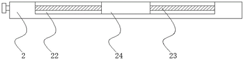
The steel grating clamping mechanism comprises a bottom plate 2, two third sliding grooves 22 which are symmetrically arranged are formed in the upper surface of the bottom plate 2, third sliding blocks 24 are connected in the third sliding grooves 22 in a sliding mode, a limiting rod 23 penetrates through and is connected with the surface of one of the third sliding blocks 24 in a sliding mode, two ends of the limiting rod 23 are fixedly connected with two ends of one of the third sliding grooves 22 respectively, another limiting rod 23 penetrates through and is connected with the other third sliding block 24 in a threaded mode, one end of the other limiting rod 23 is rotatably connected with one end of the other third sliding groove 22, the other end of the other limiting rod 23 penetrates through the bottom plate 2 and is rotatably connected with the bottom plate 2, supporting plates 25 are fixedly connected to the upper ends of the two third sliding blocks 24 respectively, mounting plates 26 are fixedly connected to the upper ends of the supporting plates 25, the mounting plates 26 are of an L-shaped plate structure, screw rods 27 penetrate through and are connected in the mounting plates 26 in a threaded mode, and the lower ends of the screw rods 27 are rotatably connected with pressing plates 28, the spacing post of upper surface one end fixedly connected with of clamp plate 28, spacing post runs through mounting panel 26 and mounting panel 26 sliding connection, put in backup pad 25 through the steel grating material that will process, the height that rotates lead screw 27 adjustment clamp plate 28 afterwards utilizes clamp plate 28 to compress tightly the steel grating in backup pad 25, twist afterwards and move the position of another gag lever post 23 adjustment third slider 24 in third spout 22, can be with the position of steel grating on the adjustment backup pad 25, the length that the steel grating needs the cutting is adjusted to the convenience.
The surface of the rotating shaft 17 penetrates through and is rotatably connected with a supporting block 18, the lower end of the supporting block 18 is fixedly connected with the inner bottom surface of the hollow rectangular block 14, and the rotating shaft 17 can rotate more stably through the supporting block 18.
The upper end fixedly connected with handle of lead screw 27 can conveniently drive lead screw 27 to rotate through rotating the handle to this can reach laborsaving effect.
The lower surface of the pressing plate 28 is fixedly connected with an anti-slip rubber pad, and the steel grating plate to be processed, which is more firmly pressed on the supporting plate 25 by the pressing plate 28, can be pressed through the anti-slip rubber pad.
As shown in fig. 1 to 5, in the present invention, preferably, the power of the first motor 7 is 500w, the power of the second motor 11 is 1kw, and the power of the third motor 16 is 1kw, and this embodiment is a method for using a movable flush head machine for processing steel grating: can drive first threaded rod 9 through starting first motor 7 and rotate, first threaded rod 9 rotates and to drive second slider 10 and remove, can drive cutting blade 13 lateral shifting on the second motor 11 and make things convenient for steel grating lateral shifting, and can adjust cutting blade 13's vertical height through elevating system, make things convenient for cutting blade 13 to cut steel grating from vertically, and can adjust the position of steel grating through steel grating fixture, cut steel grating through cutting blade 13 afterwards, it can reduce workman's labour effectively to process steel grating through replacing the manual work with the machine, and improved the stability of steel grating man-hour, the operating mass of steel grating processing work has been improved effectively.
In the description herein, references to the description of "one embodiment," "an example," "a specific example" or the like are intended to mean that a particular feature, structure, material, or characteristic described in connection with the embodiment or example is included in at least one embodiment or example of the utility model. In this specification, the schematic representations of the terms used above do not necessarily refer to the same embodiment or example. Furthermore, the particular features, structures, materials, or characteristics described may be combined in any suitable manner in any one or more embodiments or examples.
The preferred embodiments of the utility model disclosed above are intended to be illustrative only. The preferred embodiments are not intended to be exhaustive or to limit the utility model to the precise embodiments disclosed. Obviously, many modifications and variations are possible in light of the above teaching. The embodiments were chosen and described in order to best explain the principles of the utility model and the practical application, to thereby enable others skilled in the art to best utilize the utility model. The utility model is limited only by the claims and their full scope and equivalents.
Claims (6)
1. The utility model provides a steel grating processing that can remove is with neat machine, includes rectangle frame (1), its characterized in that: the inner two sides of the rectangular frame (1) are both provided with first sliding chutes (3), the first sliding chutes (3) are connected with first sliding blocks (5) in a sliding manner, the inner parts of the first sliding blocks (5) are connected with sliding rods (4) in a penetrating manner in a sliding manner, the upper ends and the lower ends of the sliding rods (4) are respectively fixedly connected with the upper ends and the lower ends of the first sliding chutes (3), one end of one first sliding block (5) is fixedly connected with a lifting block (6), the upper surface of the lifting block (6) is provided with a second sliding chute (8), the second sliding chute (8) is connected with a second sliding block (10) in a sliding manner, a first threaded rod (9) is connected in the second sliding block (10) in a penetrating manner in a threaded manner, the upper surface of the lifting block (6) is provided with a mounting groove, a first motor (7) is mounted in the mounting groove, the output end of the first motor (7) is connected with the lifting block (6) in a rotating manner through a shaft coupling and is fixedly connected with one end of the first threaded rod (9), the other end of first threaded rod (9) is rotated with the one end of second spout (8) and is connected, and second motor (11) are installed to the upper end of second slider (10), and shaft coupling fixedly connected with installation axle (12) is passed through to the output of second motor (11), and cutting blade (13) are installed to the one end of installation axle (12), and the inside below of rectangle frame (1) is provided with elevating system, and one side of rectangle frame (1) is provided with steel grating fixture.
2. The flush head machine for processing the movable steel grating as claimed in claim 1, wherein the lifting mechanism comprises a hollow rectangular block (14), the inner bottom surface of the rectangular frame (1) is fixedly connected with the hollow rectangular block (14), the lower end of the hollow rectangular block (14) is hermetically arranged, the hollow rectangular block (14) is internally and slidably connected with a solid rectangular block (15) matched with the hollow rectangular block, the upper end of the solid rectangular block (15) is fixedly connected with the lower end of the lifting block (6), a second threaded rod (19) penetrates through and is in threaded connection with the solid rectangular block (15), the lower end of the second threaded rod (19) is rotatably connected with the inner bottom surface of the hollow rectangular block (14), a first bevel gear (20) is fixedly sleeved on the surface of the second threaded rod (19), a third motor (16) is installed on the inner bottom surface of the rectangular frame (1), the output end of the third motor (16) is fixedly connected with a rotating shaft (17) through a coupler, the rotating shaft (17) penetrates through the hollow rectangular block (14) to be rotatably connected with the hollow rectangular block (14) and is fixedly connected with a second bevel gear (21), and the second bevel gear (21) is meshed with the first bevel gear (20).
3. The head trimmer for machining the movable steel grating as claimed in claim 1, wherein the steel grating clamping mechanism comprises a bottom plate (2), two third sliding grooves (22) which are symmetrically arranged are formed in the upper surface of the bottom plate (2), third sliding blocks (24) are slidably connected in the third sliding grooves (22), a limiting rod (23) penetrates through and is slidably connected to the surface of one of the third sliding blocks (24), two ends of the limiting rod (23) are fixedly connected with two ends of one of the third sliding grooves (22) respectively, another limiting rod (23) penetrates through and is in threaded connection with the other third sliding block (24), one end of the other limiting rod (23) is rotatably connected with one end of the other third sliding groove (22), the other end of the other limiting rod (23) penetrates through the bottom plate (2) and is rotatably connected with the bottom plate (2), and supporting plates (25) are fixedly connected to the upper ends of the two third sliding blocks (24), the upper end fixedly connected with mounting panel (26) of backup pad (25), mounting panel (26) are "L" shaped plate body structure, run through and threaded connection has lead screw (27) in mounting panel (26), and the lower extreme of lead screw (27) rotates and is connected with clamp plate (28), and the spacing post of upper surface one end fixedly connected with of clamp plate (28), spacing post run through mounting panel (26) and mounting panel (26) sliding connection.
4. The movable flush head machine for processing the steel grating as claimed in claim 2, wherein the surface of the rotating shaft (17) penetrates through and is rotatably connected with a supporting block (18), and the lower end of the supporting block (18) is fixedly connected with the inner bottom surface of the hollow rectangular block (14).
5. The movable flush head machine for processing the steel grating as claimed in claim 3, wherein a handle is fixedly connected to the upper end of the screw rod (27).
6. The machine of claim 3, wherein the lower surface of the pressure plate (28) is fixedly connected with a non-slip rubber pad.
Priority Applications (1)
| Application Number | Priority Date | Filing Date | Title |
|---|---|---|---|
| CN202220492289.3U CN216882871U (en) | 2022-03-09 | 2022-03-09 | Movable head aligning machine for machining steel grating |
Applications Claiming Priority (1)
| Application Number | Priority Date | Filing Date | Title |
|---|---|---|---|
| CN202220492289.3U CN216882871U (en) | 2022-03-09 | 2022-03-09 | Movable head aligning machine for machining steel grating |
Publications (1)
| Publication Number | Publication Date |
|---|---|
| CN216882871U true CN216882871U (en) | 2022-07-05 |
Family
ID=82188920
Family Applications (1)
| Application Number | Title | Priority Date | Filing Date |
|---|---|---|---|
| CN202220492289.3U Active CN216882871U (en) | 2022-03-09 | 2022-03-09 | Movable head aligning machine for machining steel grating |
Country Status (1)
| Country | Link |
|---|---|
| CN (1) | CN216882871U (en) |
-
2022
- 2022-03-09 CN CN202220492289.3U patent/CN216882871U/en active Active
Similar Documents
| Publication | Publication Date | Title |
|---|---|---|
| CN110394857B (en) | Square wood processing device | |
| CN211161683U (en) | Steel bar cutting machine | |
| CN215749648U (en) | Sliding table saw convenient to adjust and used for wood processing | |
| CN216882871U (en) | Movable head aligning machine for machining steel grating | |
| CN112139726B (en) | Beam main body welding reversible deformation device for front crane and use method thereof | |
| CN213530600U (en) | Full automatic cutout device of reinforcing bar fixed length | |
| CN219151442U (en) | Reinforcing bar cuts device for construction | |
| CN214720133U (en) | Adjustable cutting device that straightens of reinforcing bar is used in precast concrete production and processing | |
| CN216966456U (en) | Stable form H shaped steel cutting machine | |
| CN111112763A (en) | Multi freedom panel automatic tapping machine | |
| CN210589516U (en) | Carbon fiber cutting device with clamping structure | |
| CN211491679U (en) | Hair product cutting device | |
| CN212763958U (en) | Wicker cutting device is used in wickerwork handicraft processing | |
| CN212442769U (en) | Corner shearing device for processing and producing electronic device | |
| CN210306077U (en) | Cutting device for machining | |
| CN114284169A (en) | Novel automatic silicon chip splitting machine | |
| CN214777096U (en) | Cutting device for automatic packaging machine | |
| CN220498430U (en) | Cutter body cutting and separating device for scraper production | |
| CN216938731U (en) | Workpiece pressing structure of metal circular sawing machine | |
| CN212144678U (en) | High-precision plate shearing machine | |
| CN218799903U (en) | Edge cutting device for steel structure machining | |
| CN216828937U (en) | Sawing machine with pressing function for processing plates | |
| CN211111711U (en) | Glass processing equipment | |
| CN220112360U (en) | Spacing adjustable lathe cutter | |
| CN215549184U (en) | Conveying belt double-side cutting device convenient to adjust |
Legal Events
| Date | Code | Title | Description |
|---|---|---|---|
| GR01 | Patent grant | ||
| GR01 | Patent grant |