CN216876907U - Automatic turn over shaking table - Google Patents
Automatic turn over shaking table Download PDFInfo
- Publication number
- CN216876907U CN216876907U CN202220563024.8U CN202220563024U CN216876907U CN 216876907 U CN216876907 U CN 216876907U CN 202220563024 U CN202220563024 U CN 202220563024U CN 216876907 U CN216876907 U CN 216876907U
- Authority
- CN
- China
- Prior art keywords
- moving
- screw rod
- width adjusting
- turning
- limiting
- Prior art date
- Legal status (The legal status is an assumption and is not a legal conclusion. Google has not performed a legal analysis and makes no representation as to the accuracy of the status listed.)
- Expired - Fee Related
Links
- 230000007306 turnover Effects 0.000 title claims abstract description 31
- 239000000203 mixture Substances 0.000 claims description 9
- 230000006378 damage Effects 0.000 abstract description 6
- 210000000115 thoracic cavity Anatomy 0.000 abstract description 4
- 208000010392 Bone Fractures Diseases 0.000 description 2
- 206010017076 Fracture Diseases 0.000 description 2
- 206010023204 Joint dislocation Diseases 0.000 description 2
- 206010033799 Paralysis Diseases 0.000 description 2
- 210000005036 nerve Anatomy 0.000 description 2
- 210000003019 respiratory muscle Anatomy 0.000 description 2
- 208000020431 spinal cord injury Diseases 0.000 description 2
- 230000004075 alteration Effects 0.000 description 1
- 230000009286 beneficial effect Effects 0.000 description 1
- 238000005516 engineering process Methods 0.000 description 1
- 230000036541 health Effects 0.000 description 1
- 230000007246 mechanism Effects 0.000 description 1
- 230000004048 modification Effects 0.000 description 1
- 238000012986 modification Methods 0.000 description 1
- 230000000474 nursing effect Effects 0.000 description 1
- 230000003014 reinforcing effect Effects 0.000 description 1
- 238000006467 substitution reaction Methods 0.000 description 1
Images


Landscapes
- Invalid Beds And Related Equipment (AREA)
Abstract
The utility model relates to the technical field of medical instruments, in particular to an automatic turnover shaking table which comprises a bed body support, wherein a fixed bed plate is arranged above the bed body support, an overturning bed plate is arranged at the front end of the fixed bed plate, an overturning connecting rotating shaft is arranged in the fixed bed plate, a supporting rod is arranged below the overturning bed plate, a moving block is arranged below the supporting rod, a moving limiting sliding groove is arranged in the overturning bed plate, and a moving limiting sliding block is arranged in the moving limiting sliding groove; and the turnover adjusting screw rod is arranged in the bed body support. This automatic stand up shaking table promotes the movable block through rotating upset accommodate the lead screw and removes, and then improves the bracing piece and promote the upset bed board and rotate on fixed bed board, realizes assisting the patient and stands up for patient's the operation of standing up becomes simple and convenient, and the manpower has been saved in alone operation like this, again can fine protection patient's cervical vertebra thoracic vertebra, avoids more serious damage.
Description
Technical Field
The utility model relates to the technical field of medical instruments, in particular to an automatic turning shaking table.
Background
The hospital bed can be called as a hospital bed, a medical bed, a nursing bed and the like, is a hospital bed which is needed to be used when a patient is in hospital, is widely used in various hospitals, clinics, village and town health hospitals, community service centers and the like, and can be divided into a single shaking table, a double shaking table, a three shaking tables and the like as long as the patient is in hospital and needs to use the hospital bed or can not be separated from the hospital bed.
The existing shaking table can only be used for shaking up the head or the part of a bed body, the patient needing to turn over along the axis cannot be assisted to turn over, the patient can only be assisted to turn over manually, and the manual assisted turning over easily causes trunk distortion to aggravate spine fracture, spinal cord injury and joint dislocation.
SUMMERY OF THE UTILITY MODEL
The utility model aims to provide an automatic turning table concentrator, which solves the problems that the existing table concentrator in the background technology can only raise the head or the part of a bed body, can not assist a patient needing axis turning, can only assist the turning by manpower, and the trunk twisting and aggravating spine fracture, spinal cord injury and joint dislocation are easily caused by the manual assistance turning.
In order to achieve the purpose, the utility model provides the following technical scheme: an automatic turn-over cradle comprising:
the bed body support is characterized by comprising a bed body support, wherein a fixed bed board is installed above the bed body support, an overturning bed board is installed at the front end of the fixed bed board, an overturning connecting rotating shaft is installed inside the fixed bed board, a supporting rod is installed below the overturning bed board, a moving block is installed below the supporting rod, a moving limiting sliding groove is formed in the overturning bed board, and a moving limiting sliding block is installed inside the moving limiting sliding groove;
and the overturning adjusting screw rod is arranged in the bed body bracket.
Preferably, the turnover bed board is movably connected with the fixed bed board through a turnover connecting rotating shaft, the turnover bed board rotates on the fixed bed board, and the rotating angle range of the turnover bed board is 0-60 degrees.
Preferably, the turnover adjusting screw rod is movably connected with the bed body support, penetrates through the moving block and is in threaded connection with the moving block, the moving block is movably connected with the supporting rod, and the supporting rod is movably connected with the turnover bed board.
Preferably, the movable limiting slide block is further provided with:
remove the seat, it is installed remove limit slide's top, the inside of removing the seat has seted up the spacing spout of altitude mixture control, the internally mounted of the spacing spout of altitude mixture control has the spacing slider of altitude mixture control, the head mount is installed on the right side of the spacing slider of altitude mixture control, the accommodate motor is installed to the top of removing the seat, height adjusting screw is installed to accommodate motor's output, the internally mounted who removes limit slide has the removal accommodate screw.
Preferably, the movable adjusting screw rod penetrates through the inside of the movable limiting slide block, the movable adjusting screw rod is in threaded connection with the movable limiting slide block, the movable limiting slide block is fixedly connected with the movable base in an integrated mode, and the movable base moves on the turnover bed board through the movable limiting sliding groove, the movable adjusting screw rod and the movable limiting slide block.
Preferably, the head fixing frame is fixedly connected with the height adjusting limiting slide block in an integrated mode, the height adjusting screw rod penetrates through the height adjusting limiting slide block, the height adjusting screw rod is in threaded connection with the height adjusting limiting slide block, and meanwhile the head fixing frame moves on the moving seat through the height adjusting screw rod and the height adjusting limiting slide block.
Preferably, the head mount is further provided with:
the width regulation limiting sliding groove is formed in the head fixing frame, a width regulation limiting sliding block is arranged inside the width regulation limiting sliding groove, a width regulation lead screw is arranged inside the width regulation limiting sliding block, a width regulation movable plate is arranged below the width regulation limiting sliding block, the width regulation limiting sliding block is fixedly connected with the width regulation movable plate in an integrated mode, the width regulation lead screw penetrates through the inside of the width regulation limiting sliding block, the width regulation lead screw is in threaded connection with the width regulation limiting sliding block, and the width regulation movable plate is moved on the head fixing frame through the width regulation lead screw, the width regulation limiting sliding groove and the width regulation limiting sliding block.
Compared with the prior art, the utility model provides an automatic turning table concentrator, which has the following beneficial effects: this automatic stand up shaking table promotes the movable block through rotating upset accommodate the lead screw and removes, and then improves the bracing piece and promote the upset bed board and rotate on fixed bed board, realizes assisting the patient and stands up, like this can alone the operation save the manpower, again can fine protection patient's neck thoracic vertebra, avoid more serious damage.
1. According to the utility model, the movable block is pushed to move by rotating the turnover adjusting screw rod, so that the supporting rod is improved to push the turnover bed plate to rotate on the fixed bed plate, and the turnover of a patient is assisted, thus not only can one person operate to save manpower, but also the cervical vertebra and the thoracic vertebra of the patient can be well protected, and more serious damage is avoided;
2. the height adjusting screw rod is driven by the adjusting motor to rotate to push the head fixing frame to move downwards, so that the head of the patient is covered and fixed, the head of the patient is prevented from being twisted or rotated when the patient turns over, and the phenomenon that the respiratory muscle is paralyzed and died due to the damage of the nerve is avoided;
3. the utility model adjusts the distance between the width adjusting movable plate and the head fixing frame by rotating the width adjusting screw rod so as to fix heads with different sizes.
Drawings
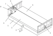
FIG. 1 is a schematic front view of the present invention;
FIG. 2 is an enlarged view of a portion of FIG. 1A;
FIG. 3 is a schematic view of the connection structure of the head fixing frame and the movable base according to the present invention;
FIG. 4 is a schematic view of the internal structure of the bed frame of the present invention.
In the figure: 1. a bed body support; 2. turning over the bed plate; 3. turning over the adjusting screw rod; 4. the connecting rotating shaft is turned over; 5. fixing the bed plate; 6. adjusting the motor; 7. a head mount; 8. a movable seat; 9. moving the limiting sliding chute; 10. moving the adjusting screw rod; 11. moving the limiting slide block; 12. a height adjusting screw rod; 13. a width adjusting screw rod; 14. a height adjusting and limiting chute; 15. a width adjustment movable plate; 16. a width adjusting limit chute; 17. a width adjusting limit slide block; 18. a height adjusting limit slide block; 19. a support bar; 20. moving the mass.
Detailed Description
The technical solutions in the embodiments of the present invention will be clearly and completely described below with reference to the drawings in the embodiments of the present invention, and it is obvious that the described embodiments are only a part of the embodiments of the present invention, and not all of the embodiments. All other embodiments, which can be derived by a person skilled in the art from the embodiments given herein without making any creative effort, shall fall within the protection scope of the present invention.
As shown in fig. 1 and 4, an automatic turn-over cradle comprises: a fixed bed plate 5 is arranged above the bed body support 1, an overturning bed plate 2 is arranged at the front end of the fixed bed plate 5, and an overturning connecting rotating shaft 4 is arranged in the fixed bed plate 5; the turnover bed board 2 is movably connected with the fixed bed board 5 through a turnover connecting rotating shaft 4, the turnover bed board 2 rotates on the fixed bed board 5, the rotating angle range of the turnover bed board 2 is 0-60 degrees, a supporting rod 19 is arranged below the turnover bed board 2, a moving block 20 is arranged below the supporting rod 19, a moving limiting sliding groove 9 is formed in the turnover bed board 2, and a moving limiting sliding block 11 is arranged in the moving limiting sliding groove 9; the overturning adjusting screw rod 3 is arranged inside the bed body bracket 1; the overturning adjusting screw rod 3 is movably connected with the bed body bracket 1, the overturning adjusting screw rod 3 penetrates through the inside of the moving block 20, the overturning adjusting screw rod 3 is in threaded connection with the moving block 20, meanwhile, the moving block 20 is movably connected with the supporting rod 19, and the supporting rod 19 is movably connected with the overturning bed plate 2; the turning adjusting screw rods 3 are rotated to push the moving blocks 20 to move, so that the supporting rods 19 are improved to push the turning bed plate 2 to rotate on the fixed bed plate 5, the patient is assisted to turn over, manpower can be saved through one-man operation, the cervical vertebra and the thoracic vertebra of the patient can be well protected, and more serious damage is avoided.
As shown in fig. 1 to 3, an automatic turn-over cradle comprises: the height adjusting mechanism comprises a moving seat 8, a height adjusting limiting sliding groove 14 is formed in the moving seat 8, a height adjusting limiting sliding block 18 is arranged in the height adjusting limiting sliding groove 14, a head fixing frame 7 is arranged on the right side of the height adjusting limiting sliding block 18, an adjusting motor 6 is arranged above the moving seat 8, a height adjusting screw rod 12 is arranged at the output end of the adjusting motor 6, and a moving adjusting screw rod 10 is arranged in the moving limiting sliding block 11; the movable adjusting screw rod 10 penetrates through the interior of the movable limiting slide block 11, the movable adjusting screw rod 10 is in threaded connection with the movable limiting slide block 11, the movable limiting slide block 11 is fixedly connected with the movable seat 8 in an integrated mode, and meanwhile the movable seat 8 moves on the turnover bed plate 2 through the movable limiting slide groove 9, the movable adjusting screw rod 10 and the movable limiting slide block 11; the head fixing frame 7 is fixedly connected with the height adjusting and limiting slide block 18 in an integrated manner, the height adjusting screw rod 12 penetrates through the height adjusting and limiting slide block 18, the height adjusting screw rod 12 is in threaded connection with the height adjusting and limiting slide block 18, and meanwhile the head fixing frame 7 moves on the moving seat 8 through the height adjusting screw rod 12 and the height adjusting and limiting slide block 18; the height adjusting screw rod 12 is driven by the adjusting motor 6 to rotate to push the head fixing frame 7 to move downwards, so that the head of the patient is covered and fixed, the head of the patient is prevented from being twisted or rotated when the patient turns over, and the phenomenon that the respiratory muscle is paralyzed and dies due to the damage of the reinforcing nerve is avoided; the head fixing frame comprises a width adjusting limiting sliding groove 16, a width adjusting limiting sliding block 17 is arranged inside the width adjusting limiting sliding groove 16, a width adjusting screw rod 13 is arranged inside the width adjusting limiting sliding block 17, a width adjusting movable plate 15 is arranged below the width adjusting limiting sliding block 17, the width adjusting limiting sliding block 17 is fixedly connected with the width adjusting movable plate 15 in an integrated mode, the width adjusting screw rod 13 penetrates through the width adjusting limiting sliding block 17, the width adjusting screw rod 13 is in threaded connection with the width adjusting limiting sliding block 17, and the width adjusting movable plate 15 moves on the head fixing frame 7 through the width adjusting screw rod 13, the width adjusting limiting sliding groove 16 and the width adjusting limiting sliding block 17; the distance between the width adjusting movable plate 15 and the head fixing frame 7 is adjusted by rotating the width adjusting screw 13, so as to fix heads with different sizes.
The working principle is as follows: when the automatic turning-over table is used, firstly a patient lies on the turning bed board 2, then the movable adjusting screw rod 10 is rotated, the movable limiting slide block 11 and the movable seat 8 on the movable limiting slide block 11 are pushed to move on the turning bed board 2 through the threads and the movable limiting slide groove 9, then the head fixing frame 7 is moved to the position right above the head of the patient, secondly, the width adjusting screw rod 13 is rotated, the width adjusting limiting slide block 17 and the width adjusting movable plate 15 below the width adjusting limiting slide block 17 are pushed to move through the threads and the width adjusting limiting slide groove 16, the distance between the width adjusting movable plate 15 and the head fixing frame 7 is adjusted to be matched with the size of the head of the patient, then the adjusting motor 6 is electrified to drive the height adjusting screw rod 12 to rotate, the head fixing frame 7 is pushed to move downwards through the threads, so that the head fixing frame 7 covers and fixes the head of the patient, finally, the overturning adjusting screw rod 3 is rotated, the moving block 20 is pushed to move through threads, and then the overturning bed plate 2 is pushed to rotate on the fixed bed plate 5 through the supporting rod 19, so that the overturning of the patient is assisted.
Although embodiments of the present invention have been shown and described, it will be appreciated by those skilled in the art that changes, modifications, substitutions and alterations can be made in these embodiments without departing from the principles and spirit of the utility model, the scope of which is defined in the appended claims and their equivalents.
Claims (7)
1. An automatic turnover shaking table is characterized by comprising:
the bed body support is characterized by comprising a bed body support (1), a fixed bed board (5) is installed above the bed body support (1), an overturning bed board (2) is installed at the front end of the fixed bed board (5), an overturning connecting rotating shaft (4) is installed inside the fixed bed board (5), a supporting rod (19) is installed below the overturning bed board (2), a moving block (20) is installed below the supporting rod (19), a moving limiting sliding groove (9) is formed in the overturning bed board (2), and a moving limiting sliding block (11) is installed inside the moving limiting sliding groove (9);
and the overturning adjusting screw rod (3) is arranged in the bed body bracket (1).
2. The automatic turning-over table concentrator as claimed in claim 1, wherein the turning-over table (2) is movably connected with the fixed table (5) by the turning-over connecting rotating shaft (4), and the turning-over table (2) is rotated on the fixed table (5), and the rotating angle range of the turning-over table (2) is 0-60 °.
3. The automatic turning table concentrator as claimed in claim 1, wherein the turning adjusting screw rod (3) is movably connected with the bed body support (1), the turning adjusting screw rod (3) penetrates through the inside of the moving block (20), the turning adjusting screw rod (3) is in threaded connection with the moving block (20), the moving block (20) is movably connected with the supporting rod (19), and the supporting rod (19) is movably connected with the turning bed plate (2).
4. The automatic turning-over cradle according to claim 1, characterized in that said mobile limit slider (11) is further provided with:
remove seat (8), it is installed the top of removing limit slide (11), altitude mixture control limit chute (14) have been seted up to the inside of removing seat (8), the internally mounted of altitude mixture control limit chute (14) has altitude mixture control limit slide (18), head mount (7) are installed on the right side of altitude mixture control limit slide (18), adjusting motor (6) are installed to the top of removing seat (8), altitude mixture control lead screw (12) are installed to the output of adjusting motor (6), the internally mounted who removes limit slide (11) has removal adjusting lead screw (10).
5. The automatic turning table concentrator as claimed in claim 4, wherein the moving adjusting screw rod (10) penetrates through the inside of the moving limiting slide block (11), the moving adjusting screw rod (10) is in threaded connection with the moving limiting slide block (11), the moving limiting slide block (11) is fixedly connected with the moving seat (8) in an integrated manner, and the moving seat (8) moves on the turnover bed plate (2) through the moving limiting chute (9), the moving adjusting screw rod (10) and the moving limiting slide block (11).
6. The automatic turn-over shaking table as claimed in claim 4, wherein the head holder (7) is fixedly connected with the height adjustment limiting slider (18) in an integral manner, and the height adjustment screw rod (12) penetrates through the inside of the height adjustment limiting slider (18), and the height adjustment screw rod (12) is in threaded connection with the height adjustment limiting slider (18), and meanwhile the head holder (7) is moved on the moving seat (8) through the height adjustment screw rod (12) and the height adjustment limiting slider (18).
7. The automatic turning table concentrator as claimed in claim 4, wherein the head holder (7) is further provided with:
a width adjusting and limiting sliding groove (16) which is arranged inside the head fixing frame (7), a width adjusting limit sliding block (17) is arranged in the width adjusting limit sliding groove (16), a width adjusting screw rod (13) is arranged in the width adjusting limiting slide block (17), a width adjusting movable plate (15) is arranged below the width adjusting limiting slide block (17), the width adjusting limit slide block (17) is fixedly connected with the width adjusting movable plate (15) in an integrated manner, the width adjusting screw rod (13) penetrates through the inside of the width adjusting limiting slide block (17), the width adjusting screw rod (13) is connected with a width adjusting limit slide block (17) through screw threads, the width adjusting movable plate (15) moves on the head fixing frame (7) through a width adjusting screw rod (13), a width adjusting limiting sliding groove (16) and a width adjusting limiting sliding block (17).
Priority Applications (1)
| Application Number | Priority Date | Filing Date | Title |
|---|---|---|---|
| CN202220563024.8U CN216876907U (en) | 2022-03-15 | 2022-03-15 | Automatic turn over shaking table |
Applications Claiming Priority (1)
| Application Number | Priority Date | Filing Date | Title |
|---|---|---|---|
| CN202220563024.8U CN216876907U (en) | 2022-03-15 | 2022-03-15 | Automatic turn over shaking table |
Publications (1)
| Publication Number | Publication Date |
|---|---|
| CN216876907U true CN216876907U (en) | 2022-07-05 |
Family
ID=82190108
Family Applications (1)
| Application Number | Title | Priority Date | Filing Date |
|---|---|---|---|
| CN202220563024.8U Expired - Fee Related CN216876907U (en) | 2022-03-15 | 2022-03-15 | Automatic turn over shaking table |
Country Status (1)
| Country | Link |
|---|---|
| CN (1) | CN216876907U (en) |
Cited By (1)
| Publication number | Priority date | Publication date | Assignee | Title |
|---|---|---|---|---|
| CN115120430A (en) * | 2022-08-30 | 2022-09-30 | 吉林大学 | Neurosurgery tumour basis nursing device |
-
2022
- 2022-03-15 CN CN202220563024.8U patent/CN216876907U/en not_active Expired - Fee Related
Cited By (2)
| Publication number | Priority date | Publication date | Assignee | Title |
|---|---|---|---|---|
| CN115120430A (en) * | 2022-08-30 | 2022-09-30 | 吉林大学 | Neurosurgery tumour basis nursing device |
| CN115120430B (en) * | 2022-08-30 | 2022-11-11 | 吉林大学 | Neurosurgery tumour basis nursing device |
Similar Documents
| Publication | Publication Date | Title |
|---|---|---|
| CN107349042A (en) | A kind of Orthopaedic nursing towing bracket | |
| CN111803190A (en) | Clinical anesthesia puncture fixing device that uses of painful branch of academic or vocational study of slidingtype | |
| CN208989504U (en) | A kind of Orthopaedic nursing dressing change rack | |
| CN208677828U (en) | A kind of department of general surgery's instrument table | |
| CN209377953U (en) | A kind of Intensive Care Therapy device | |
| CN218220169U (en) | Stable convenient-to-operate vaginal dilator | |
| CN215081562U (en) | Vertebral column fracture position resetting device | |
| CN216167802U (en) | Clinical nail ware of getting of orthopedics | |
| CN215019804U (en) | Treatment auxiliary device for orthopedic sports trauma and arthroscopic surgery | |
| CN216495462U (en) | Device for cardiovascular interventional surgical treatment | |
| CN214806249U (en) | Pillow with adjustable angle | |
| CN213220568U9 (en) | Postpartum physical therapy device for obstetrics and gynecology department | |
| CN215079908U (en) | Mouth gag for rescue | |
| CN213697756U (en) | Fixing device for orthopedic surgery | |
| CN215900235U (en) | Auxiliary supporting device for ear-nose-throat-head-neck surgical nursing | |
| CN217138562U (en) | A rehabilitation training device for gynaecology and obstetrics's nursing | |
| CN223438959U (en) | Auxiliary stand for anesthesia | |
| CN220558252U (en) | Combined columnar anesthesia bed fixing support | |
| CN218484782U (en) | Auxiliary device for turning over | |
| CN208659823U (en) | A kind of obstetrical nursing lower limb support adjustable apparatus | |
| CN216985477U (en) | Bed with axis capable of turning over | |
| CN222487979U (en) | An upper limb support frame for plastic surgery | |
| CN209286037U (en) | A kind of gynecological disease diagnosis and treatment bed | |
| CN209172628U (en) | A kind of orthopaedics auxiliary clamping plate installation clamp device | |
| CN220917654U (en) | Leg supporting device |
Legal Events
| Date | Code | Title | Description |
|---|---|---|---|
| GR01 | Patent grant | ||
| GR01 | Patent grant | ||
| CF01 | Termination of patent right due to non-payment of annual fee | ||
| CF01 | Termination of patent right due to non-payment of annual fee |
Granted publication date: 20220705 |