CN216860032U - Furniture manufacturing is with cutting out material machine - Google Patents
Furniture manufacturing is with cutting out material machine Download PDFInfo
- Publication number
- CN216860032U CN216860032U CN202122935616.6U CN202122935616U CN216860032U CN 216860032 U CN216860032 U CN 216860032U CN 202122935616 U CN202122935616 U CN 202122935616U CN 216860032 U CN216860032 U CN 216860032U
- Authority
- CN
- China
- Prior art keywords
- fixed
- conical gear
- driving motor
- support
- threaded
- Prior art date
- Legal status (The legal status is an assumption and is not a legal conclusion. Google has not performed a legal analysis and makes no representation as to the accuracy of the status listed.)
- Active
Links
- 238000004519 manufacturing process Methods 0.000 title claims abstract description 46
- 238000005520 cutting process Methods 0.000 title claims abstract description 42
- 239000000463 material Substances 0.000 title claims abstract description 15
- 238000012546 transfer Methods 0.000 claims abstract description 10
- 230000008878 coupling Effects 0.000 claims 1
- 238000010168 coupling process Methods 0.000 claims 1
- 238000005859 coupling reaction Methods 0.000 claims 1
- 238000006073 displacement reaction Methods 0.000 abstract 2
- 239000002023 wood Substances 0.000 description 8
- 230000005540 biological transmission Effects 0.000 description 6
- 230000006870 function Effects 0.000 description 3
- 230000000694 effects Effects 0.000 description 2
- 230000005012 migration Effects 0.000 description 2
- 238000013508 migration Methods 0.000 description 2
- 238000012986 modification Methods 0.000 description 2
- 230000004048 modification Effects 0.000 description 2
- 230000035807 sensation Effects 0.000 description 2
- 241000282414 Homo sapiens Species 0.000 description 1
- 230000009286 beneficial effect Effects 0.000 description 1
- 230000007547 defect Effects 0.000 description 1
- 238000011161 development Methods 0.000 description 1
- 238000000034 method Methods 0.000 description 1
- 230000001737 promoting effect Effects 0.000 description 1
Images


Landscapes
- Processing Of Stones Or Stones Resemblance Materials (AREA)
Abstract
The utility model relates to the technical field of furniture production and manufacturing, and discloses a material cutting machine for furniture production and manufacturing. This furniture is cut out material machine for manufacturing, through setting up first driving motor, the mounting panel, first screw thread post, first conical gear, the reading pole, the scale mark, the movable block, the screw hole, the through-hole, the arc piece, the transfer line, third conical gear, the dwang, fourth conical gear, the carousel, handle and second conical gear, first driving motor drives first screw thread post, make the movable block remove to the right, through carrying out the reading to the scale mark on the reading pole, thereby carry out accurate control to the cutting length of plank, first conical gear, the transfer line, second conical gear, third conical gear, the dwang, fourth conical gear, cooperation between carousel and the handle, can finely tune the displacement of movable block, in order to ensure displacement's accuracy.
Description
Technical Field
The utility model relates to the technical field of furniture production and manufacturing, in particular to a material cutting machine for furniture production and manufacturing.
Background
Furniture refers to a large variety of appliances and facilities essential for human beings to maintain normal life, engage in production practice and develop social activities, and the furniture is continuously developed and innovated along with the foot steps of the times, so that the furniture is a great variety, different in materials, complete in variety and different in purposes at present, and is an important basis for establishing working and living spaces. The furniture is composed of four factors of materials, structures, appearance forms and functions, wherein the functions are the leading factors and the power for promoting the development of the furniture; the structure is a backbone and is the basis for realizing the functions.
Some cutting machines on the market today:
when using, adopt the cutting piece to cut out the material to timber, however, at the in-process of cutting out the material, can't carry out the accuracy according to actual demand to the cutting length of timber and control, lead to timber to scrap easily to the cost of manufacture of furniture has been increased.
We propose a cutting machine for furniture production and manufacture in order to solve the problems set forth above.
SUMMERY OF THE UTILITY MODEL
Technical problem to be solved
Aiming at the defects of the prior art in the background art, the utility model aims to provide a cutting machine for furniture production and manufacturing, which solves the problems that in the cutting process of some cutting machines for furniture production and manufacturing in the current market provided in the background art, the cutting length of wood cannot be accurately controlled according to actual requirements, so that the wood is easily scrapped, and the furniture manufacturing cost is increased.
(II) technical scheme
In order to achieve the purpose, the utility model is realized by the following technical scheme:
a cutting machine for furniture production and manufacturing comprises a bottom plate, wherein supporting columns are fixed at four ends of the bottom plate, a first support, a baffle, a vertical plate, a second support and a fixing box are sequentially fixed at the top of the bottom plate from the right side, a first air cylinder is fixed at the left side of the vertical plate, a clamping plate is fixed at the telescopic end of the first air cylinder, a first driving motor is fixed at the top of the first support, a mounting plate is fixed at the top of the second support, the output end of the first driving motor is connected with a first threaded column through a coupler, the right end of the first threaded column penetrates through the mounting plate and is fixed with a first bevel gear, the first threaded column is rotatably connected with the mounting plate through a bearing, a reading rod is fixed at the upper end of the right side of the first support, the right end of the reading rod is fixed with the upper end of the left side of the second support, scale marks are arranged on the outer side of the reading rod, the outer side of the first threaded column is in threaded connection with a moving block, one side of the moving block is provided with a threaded hole and a through hole, two arc-shaped blocks are fixed on the inner side of the through hole and are symmetrically arranged, the first threaded column is in threaded connection with the inner side of the threaded hole, one end of the reading rod penetrates through the through hole, the arc-shaped blocks are in contact with the outer side of the reading rod, a second air cylinder is fixed at the bottom of the moving block, a mounting frame is fixed at the telescopic end of the second air cylinder, a guide rod is fixed on the inner side of the mounting frame, a second driving motor is fixed on the front side of the mounting frame, a second threaded column is fixed at the output end of the second driving motor, the rear end of the second threaded column is in rotating connection with the inner rear side of the mounting frame through a bearing, a moving plate is in threaded connection with the outer side of the second threaded column, and penetrates through the guide rod, the left side of movable plate is fixed with third driving motor, third driving motor's output is fixed with cutting blade, the right-hand member of second support is fixed with the diaphragm, the top of diaphragm is rotated and is connected with the transfer line, the top of transfer line is fixed with second bevel gear, second bevel gear and first bevel gear meshing are connected, the bottom of transfer line runs through the top of diaphragm and fixed box in proper order and is fixed with third bevel gear, the right side of fixed box is rotated and is connected with the dwang, the left end of dwang runs through the right side of fixed box and is fixed with fourth bevel gear, fourth bevel gear is connected with third bevel gear meshing, the right-hand member of dwang is fixed with the carousel, the right side of carousel is fixed with the handle.
Preferably, the bottom of the supporting column is bonded with a non-slip mat, the non-slip mat is made of rubber materials, and the purpose of preventing the cutting machine from slipping can be achieved through the non-slip mat.
Preferably, the cutting edge of the cutting blade and the left side of the moving block are located on the same plane, and the mounting frame is in a U shape.
Preferably, the flexible sleeve is bonded on the outer side of the handle and is a sponge sleeve, so that the comfortable sensation of the handle during use can be enhanced through the flexible sleeve.
Furthermore, the outer diameter value of the guide rod is smaller than that of the second threaded column, and the second threaded column and the guide rod are parallel to each other.
Furthermore, one side of the arc-shaped block in contact with the reading rod is arc-shaped, the arc-shaped block is not in contact with the scale marks, and the moving block can be prevented from damaging the scale marks.
(III) advantageous effects
Compared with the prior art, the utility model has the beneficial effects that: this furniture is tailor material machine for manufacturing:
when using, through setting up first driving motor, the mounting panel, first screw thread post, first conical gear, the reading pole, the scale mark, the movable block, the screw hole, the through-hole, the arc piece, the transfer line, the third conical gear, the dwang, the fourth conical gear, the carousel, handle and second conical gear, first driving motor drives first screw thread post, make the movable block remove rightwards, through reading the scale mark on the reading pole, thereby carry out accurate control to the cutting length of plank, first conical gear, the transfer line, the second conical gear, the third conical gear, the dwang, the fourth conical gear, cooperation between carousel and the handle, can finely tune the migration distance of movable block, in order to ensure migration distance's accuracy, in order to avoid appearing the condemned phenomenon of timber.
Drawings
FIG. 1 is a schematic sectional view of a cutting machine for furniture production and manufacture according to the present invention;
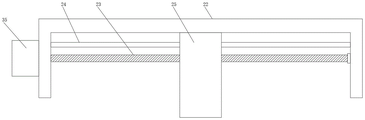
FIG. 2 is a schematic sectional front view of a mounting rack of the cutting machine for furniture production and manufacturing according to the present invention;
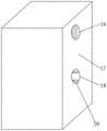
FIG. 3 is a schematic perspective view of a moving block of the cutting machine for furniture production and manufacturing according to the present invention;
fig. 4 is a schematic side view of the mounting frame of the cutting machine for furniture production and manufacturing according to the present invention.
In the figure: 1. a base plate; 2. a support column; 3. a non-slip mat; 4. a first bracket; 5. a baffle plate; 6. a vertical plate; 7. a second bracket; 8. a fixed box; 9. a first cylinder; 10. a splint; 11. a first drive motor; 12. mounting a plate; 13. a first threaded post; 14. a first bevel gear; 15. a reading rod; 16. scale lines; 17. a moving block; 18. a threaded hole; 19. a through hole; 20. an arc-shaped block; 21. a second cylinder; 22. a mounting frame; 23. a second threaded post; 24. a guide bar; 25. moving the plate; 26. a third drive motor; 27. a cutting blade; 28. a transverse plate; 29. a transmission rod; 30. a third bevel gear; 31. rotating the rod; 32. a fourth bevel gear; 33. a turntable; 34. a handle; 35. a second drive motor; 36. a second bevel gear.
Detailed Description
The technical solutions in the embodiments of the present invention will be clearly and completely described below with reference to the drawings in the embodiments of the present invention, and it is obvious that the described embodiments are only a part of the embodiments of the present invention, and not all of the embodiments. All other embodiments, which can be derived by a person skilled in the art from the embodiments given herein without making any creative effort, shall fall within the protection scope of the present invention.
Referring to fig. 1-4, the present invention provides a cutting machine for furniture manufacturing; comprises a bottom plate 1, supporting columns 2 are fixed at four ends of the bottom plate 1, a first support 4, a baffle 5, a vertical plate 6, a second support 7 and a fixed box 8 are sequentially fixed at the top of the bottom plate 1 from the right, a first air cylinder 9 is fixed at the left side of the vertical plate 6, a clamping plate 10 is fixed at the telescopic end of the first air cylinder 9, a first driving motor 11 is fixed at the top of the first support 4, a mounting plate 12 is fixed at the top of the second support 7, the output end of the first driving motor 11 is connected with a first threaded column 13 through a coupler, the right end of the first threaded column 13 penetrates through the mounting plate 12 and is fixed with a first bevel gear 14, the first threaded column 13 is rotatably connected with the mounting plate 12 through a bearing, a reading rod 15 is fixed at the upper end of the right side of the first support 4, the right end of the reading rod 15 is fixed with the upper end of the left side of the second support 7, a scale mark 16 is arranged at the outer side of the reading rod 15, and a moving block 17 is in threaded connection with the outer side of the first threaded column 13, one side of a moving block 17 is provided with a threaded hole 18 and a through hole 19, two arc-shaped blocks 20 are fixed on the inner side of the through hole 19, the two arc-shaped blocks 20 are symmetrically arranged, a first threaded column 13 is in threaded connection with the inner side of the threaded hole 18, one end of a reading rod 15 penetrates through the through hole 19, the arc-shaped blocks 20 are in contact with the outer side of the reading rod 15, a second air cylinder 21 is fixed at the bottom of the moving block 17, a mounting frame 22 is fixed at the telescopic end of the second air cylinder 21, a guide rod 24 is fixed on the inner side of the mounting frame 22, a second driving motor 35 is fixed on the front side of the mounting frame 22, a second threaded column 23 is fixed at the output end of the second driving motor 35, the rear end of the second threaded column 23 is in rotating connection with the inner rear side of the mounting frame 22 through a bearing, a moving plate 25 is in threaded connection with the outer side of the second threaded column moving plate 23, the guide rod 24 penetrates through 25, and a third driving motor 26 is fixed on the left side of the moving plate 25, a cutting blade 27 is fixed at the output end of the third driving motor 26, a transverse plate 28 is fixed at the right end of the second bracket 7, a transmission rod 29 is rotatably connected to the top of the transverse plate 28, a second bevel gear 36 is fixed at the top of the transmission rod 29, the second bevel gear 36 is meshed with the first bevel gear 14, the bottom end of the transmission rod 29 sequentially penetrates through the transverse plate 28 and the top of the fixed box 8 and is fixed with a third bevel gear 30, a rotating rod 31 is rotatably connected to the right side of the fixed box 8, the left end of the rotating rod 31 penetrates through the right side of the fixed box 8 and is fixed with a fourth bevel gear 32, the fourth bevel gear 32 is meshed with the third bevel gear 30, a rotating disc 33 is fixed at the right end of the rotating rod 31, and a handle 34 is fixed at the right side of the rotating disc 33;
as a preferred technical scheme of the utility model: the anti-skid pad 3 is bonded at the bottom of the support column 2, the anti-skid pad 3 is made of rubber materials, and the anti-skid purpose of the material cutting machine can be achieved through the anti-skid pad 3;
as a preferred technical scheme of the utility model: the cutting edge of the cutting blade 27 and the left side of the moving block 17 are positioned on the same plane, and the mounting frame 22 is U-shaped;
as a preferred technical scheme of the utility model: a flexible sleeve is bonded on the outer side of the handle 34, and is a sponge sleeve, so that the comfortable sensation of the handle 34 in use can be enhanced through the flexible sleeve;
as a preferred technical scheme of the utility model: the outer diameter value of the guide rod 24 is smaller than that of the second threaded column 23, the second threaded column 23 and the guide rod 24 are parallel to each other, a controller is fixed on one side of the bottom plate 1, and the first air cylinder 9, the first driving motor 11, the second air cylinder 21, the second driving motor 35 and the third driving motor 26 are connected with the controller;
as a preferred technical scheme of the utility model: the arc block 20 is arc-shaped on the side contacting with the reading rod 15, the arc block 20 does not contact with the scale marks 16, and the moving block 17 can be prevented from damaging the scale marks 16 through the arc block 20.
The working principle of the embodiment is as follows: when the cutting machine for manufacturing and manufacturing furniture is used, as shown in fig. 1-4, firstly, wood is placed on the top of the bottom plate 1, one end of the wood is contacted with the right side of the baffle plate 5, then the first air cylinder 9 is started, the right side of the wood is pressed through the clamping plate 10, so that the wood is fixed on the top of the bottom plate 1, then the first driving motor 11 is started, the moving block 17 is driven by the first threaded column 13 to move leftwards, the moving length of the moving block 17 is controlled according to actual requirements, then the handle 34 is rotated, the fourth conical gear 32 on the rotating rod 31 is meshed with the third conical gear 30 at the bottom end of the transmission rod 29, so that the second conical gear 36 at the top end of the transmission rod 29 is driven to be meshed with the first conical gear 14, the first threaded column 13 is rotated, so that the position of the moving block 17 is finely adjusted and the scale mark 16 on the reading rod 15 is observed, then the second air cylinder 21 and the third driving motor 26 are started, the mounting frame 22 is driven to move downwards by the second air cylinder 21, finally the second driving motor 35 is started, the moving plate 25 is driven to move backwards by the second threaded column 23, and the cutting blade 27 is driven by the third driving motor 26 to cut the wood while moving, so as to ensure the accuracy of the cutting length of the wood.
Although the present invention has been described in detail with reference to the foregoing embodiments, it should be noted that, in the present invention, unless otherwise explicitly specified or limited, the terms "disposed," "mounted," "connected," "fixed," and the like are to be construed broadly, and for example, may be fixedly connected or detachably connected; or indirectly through an intermediary. The specific meanings of the above terms in the present invention can be understood by those skilled in the art according to specific situations; it will be appreciated by those skilled in the art that various modifications may be made to the embodiments described above, or equivalents may be substituted for some of the features thereof, and any modifications, equivalents, improvements or the like which fall within the spirit and scope of the present invention are intended to be included therein.
Claims (6)
1. The utility model provides a furniture production manufacturing is with cutting out material machine, includes bottom plate (1), its characterized in that, four ends in the bottom of bottom plate (1) all are fixed with support column (2), the top of bottom plate (1) is fixed with first support (4), baffle (5), riser (6), second support (7) and fixed box (8) from accomplishing the right side in proper order, the left side of riser (6) is fixed with first cylinder (9), the flexible end of first cylinder (9) is fixed with splint (10), the top of first support (4) is fixed with first driving motor (11), the top of second support (7) is fixed with mounting panel (12), the output of first driving motor (11) has first screw thread post (13) through the coupling joint, the right-hand member of first screw thread post (13) runs through mounting panel (12) and is fixed with first conical gear (14), the first threaded column (13) is rotatably connected with the mounting plate (12) through a bearing, a reading rod (15) is fixed at the upper end of the right side of the first support (4), the right end of the reading rod (15) is fixed with the upper end of the left side of the second support (7), a scale mark (16) is arranged on the outer side of the reading rod (15), a moving block (17) is in threaded connection with the outer side of the first threaded column (13), a threaded hole (18) and a through hole (19) are formed in one side of the moving block (17), two arc-shaped blocks (20) are fixed on the inner side of the through hole (19), the two arc-shaped blocks (20) are symmetrically arranged, the first threaded column (13) is in threaded connection with the inner side of the threaded hole (18), one end of the reading rod (15) penetrates through the through hole (19), the arc-shaped blocks (20) are in contact with the outer side of the reading rod (15), a second air cylinder (21) is fixed at the bottom of the moving block (17), the telescopic end of second cylinder (21) is fixed with mounting bracket (22), the inboard of mounting bracket (22) is fixed with guide bar (24), the front side of mounting bracket (22) is fixed with second driving motor (35), the output of second driving motor (35) is fixed with second screw thread post (23), the rear end of second screw thread post (23) passes through the bearing and is connected with the interior rear side rotation of mounting bracket (22), the outside threaded connection of second screw thread post (23) has movable plate (25), guide bar (24) run through movable plate (25), the left side of movable plate (25) is fixed with third driving motor (26), the output of third driving motor (26) is fixed with cutting blade (27), the right-hand member of second support (7) is fixed with diaphragm (28), the top of diaphragm (28) is rotated and is connected with transfer line (29), the top of transfer line (29) is fixed with second conical gear (36), second conical gear (36) and first conical gear (14) meshing connection, the bottom of transfer line (29) runs through the top of diaphragm (28) and fixed case (8) in proper order and is fixed with third conical gear (30), the right side of fixed case (8) is rotated and is connected with dwang (31), the right side that fixed case (8) was run through to the left end of dwang (31) is fixed with fourth conical gear (32), fourth conical gear (32) are connected with third conical gear (30) meshing, the right-hand member of dwang (31) is fixed with carousel (33), the right side of carousel (33) is fixed with handle (34).
2. The cutting machine for furniture production and manufacture according to claim 1, characterized in that a non-slip mat (3) is adhered to the bottom of the supporting column (2), and the non-slip mat (3) is made of rubber material.
3. The cutting machine for furniture production and manufacture according to claim 1, wherein the cutting edge of the cutting blade (27) and the left side of the moving block (17) are located on the same plane, and the mounting frame (22) is in a U shape.
4. The cutting machine for furniture production and manufacture according to claim 1, characterized in that a flexible sleeve is bonded on the outer side of the handle (34), and the flexible sleeve is a sponge sleeve.
5. The cutting machine for the furniture production and manufacture according to claim 1, characterized in that the guide bar (24) has an outer diameter smaller than the outer diameter of the second threaded post (23), the second threaded post (23) and the guide bar (24) being parallel to each other.
6. The cutting machine for furniture production and manufacturing according to claim 1, characterized in that the side of the arc-shaped block (20) contacting the reading rod (15) is arc-shaped, and the arc-shaped block (20) does not contact the scale marks (16).
Priority Applications (1)
| Application Number | Priority Date | Filing Date | Title |
|---|---|---|---|
| CN202122935616.6U CN216860032U (en) | 2021-11-26 | 2021-11-26 | Furniture manufacturing is with cutting out material machine |
Applications Claiming Priority (1)
| Application Number | Priority Date | Filing Date | Title |
|---|---|---|---|
| CN202122935616.6U CN216860032U (en) | 2021-11-26 | 2021-11-26 | Furniture manufacturing is with cutting out material machine |
Publications (1)
| Publication Number | Publication Date |
|---|---|
| CN216860032U true CN216860032U (en) | 2022-07-01 |
Family
ID=82127541
Family Applications (1)
| Application Number | Title | Priority Date | Filing Date |
|---|---|---|---|
| CN202122935616.6U Active CN216860032U (en) | 2021-11-26 | 2021-11-26 | Furniture manufacturing is with cutting out material machine |
Country Status (1)
| Country | Link |
|---|---|
| CN (1) | CN216860032U (en) |
-
2021
- 2021-11-26 CN CN202122935616.6U patent/CN216860032U/en active Active
Similar Documents
| Publication | Publication Date | Title |
|---|---|---|
| CN112571547A (en) | Wood cutting equipment for carpenter | |
| CN209784409U (en) | Optical detection tool of flat panel display LCD module | |
| CN216939567U (en) | Horizontal numerical control clamping device for ray apparatus | |
| CN211616305U (en) | Plastic rim charge cutting device is used in light guide plate production | |
| CN208035025U (en) | A kind of ceramics cutting equipment | |
| CN218557413U (en) | Wood board cutting device for wood processing | |
| CN217890494U (en) | Polishing machine for processing optical glass sheets | |
| CN219051764U (en) | Paint layer spraying equipment on surface of plate | |
| CN211440151U (en) | Cutting device for building material | |
| CN211104243U (en) | Trimmer for production and preparation of plastic products | |
| CN212355956U (en) | Paperboard cutting device for well packaged paperboards | |
| CN210334607U (en) | Anchor clamps for machining | |
| CN203999353U (en) | a cutting machine | |
| CN224089014U (en) | Board line drawing equipment based on wooden bar counter processing | |
| CN114161495A (en) | Cutting device with adjustable specification and size for organic glass production and use method thereof | |
| CN224027867U (en) | Simple woodworking sawing machine | |
| CN222681518U (en) | A device for removing burrs of rubber products | |
| CN113696280B (en) | Ancient building and archaize building's decoration and fitment device | |
| CN212763798U (en) | Automatic control device for laser cutting die for die | |
| CN219882942U (en) | Infrared bridge type stone cutting machine convenient for feeding | |
| CN210452980U (en) | Environment-friendly polymer plastic uptake plate high accuracy cutting device | |
| CN220994630U (en) | Paper positioning and aligning mechanism of paper cutting machine | |
| CN222947136U (en) | Packaging machine for advertisement design | |
| CN220649426U (en) | Full-automatic universal length measuring instrument | |
| CN223044691U (en) | Yoga mat trimming device |
Legal Events
| Date | Code | Title | Description |
|---|---|---|---|
| GR01 | Patent grant | ||
| GR01 | Patent grant |