CN216859461U - Positioning and pressing device for machining mechanical parts - Google Patents

Positioning and pressing device for machining mechanical parts Download PDF

Info

Publication number
CN216859461U
CN216859461U CN202123272010.5U CN202123272010U CN216859461U CN 216859461 U CN216859461 U CN 216859461U CN 202123272010 U CN202123272010 U CN 202123272010U CN 216859461 U CN216859461 U CN 216859461U
Authority
CN
China
Prior art keywords
plate
positioning
mounting plate
mechanical parts
pressing device
Prior art date
Legal status (The legal status is an assumption and is not a legal conclusion. Google has not performed a legal analysis and makes no representation as to the accuracy of the status listed.)
Expired - Fee Related
Application number
CN202123272010.5U
Other languages
Chinese (zh)
Inventor
张文奇
Current Assignee (The listed assignees may be inaccurate. Google has not performed a legal analysis and makes no representation or warranty as to the accuracy of the list.)
Dalian Hetai Precision Industry Co ltd
Original Assignee
Dalian Hetai Precision Industry Co ltd
Priority date (The priority date is an assumption and is not a legal conclusion. Google has not performed a legal analysis and makes no representation as to the accuracy of the date listed.)
Filing date
Publication date
Application filed by Dalian Hetai Precision Industry Co ltd filed Critical Dalian Hetai Precision Industry Co ltd
Priority to CN202123272010.5U priority Critical patent/CN216859461U/en
Application granted granted Critical
Publication of CN216859461U publication Critical patent/CN216859461U/en
Expired - Fee Related legal-status Critical Current
Anticipated expiration legal-status Critical

Links

Images

Landscapes

  • Press Drives And Press Lines (AREA)

Abstract

本实用新型公开了一种机械零部件加工用定位压紧装置,包括操作台和支腿,所述操作台顶部两端对称设置有液压杆,所述液压杆的输出端连接有安装板,所述安装板上设置有压紧组件和导向组件;所述压紧组件,用于对零件进行固定,包括设置在安装板顶部远离液压杆一侧的固定板,所述固定板上设置有与其螺纹配合的螺纹杆,所述螺纹杆一端贯穿固定板并连接有压板,所述螺纹杆远离压板的一端设置有旋钮,通过设置有导向组件,使零件被固定后便于在与液压杆的延长方向垂直的方向上对零件的位置进行移动或调整,实用性强。

Figure 202123272010

The utility model discloses a positioning and pressing device for machining mechanical parts, which comprises an operating table and outriggers. Hydraulic rods are symmetrically arranged at both ends of the top of the operating table, and an output end of the hydraulic rods is connected with a mounting plate. The mounting plate is provided with a pressing component and a guiding component; the pressing component is used to fix the parts, including a fixing plate arranged on the top of the mounting plate away from the hydraulic rod, and the fixing plate is provided with a thread thereon. Matching threaded rod, one end of the threaded rod penetrates the fixing plate and is connected with the pressure plate, and the end of the threaded rod away from the pressure plate is provided with a knob, and the guide assembly is provided, so that the parts are fixed and easy to be perpendicular to the extension direction of the hydraulic rod. It is very practical to move or adjust the position of the parts in the direction of the machine.

Figure 202123272010

Description

Positioning and pressing device for machining mechanical parts
Technical Field
The utility model relates to the technical field of machining equipment, in particular to a positioning and pressing device for machining mechanical parts.
Background
The mechanical parts are not only a discipline for researching and designing mechanical basic parts in various devices, but also are general names of parts and components, and since the machines appeared, corresponding mechanical parts exist. During the processing of parts, the workpieces need to be centered and pressed for processing.
The existing device is inconvenient to compress tightly the part of size difference when using fixedly, influences result of use and application range, and inconvenient position to the part is adjusted when the part is fixed back, influences the convenience of use and the flexibility of device.
In order to solve the problems, an improved positioning and pressing device for machining mechanical parts is designed.
SUMMERY OF THE UTILITY MODEL
The utility model aims to provide a positioning and pressing device for machining mechanical parts, which aims to solve the problems in the background technology.
In order to achieve the purpose, the utility model provides the following technical scheme:
a positioning and pressing device for machining mechanical parts comprises an operation table and supporting legs, wherein hydraulic rods are symmetrically arranged at two ends of the top of the operation table, the output ends of the hydraulic rods are connected with an installation plate, and a pressing assembly and a guide assembly are arranged on the installation plate;
the pressing assembly is used for fixing parts and comprises a fixing plate which is arranged at the top of the mounting plate and is far away from one side of the hydraulic rod, a threaded rod matched with the fixing plate in a threaded mode is arranged on the fixing plate, one end of the threaded rod penetrates through the fixing plate and is connected with a pressing plate, and a knob is arranged at one end, far away from the pressing plate, of the threaded rod.
Preferably, the direction subassembly makes the part be convenient for remove after being compressed tightly, includes that a plurality of slides set up in the mounting panel bottom and run through the slide bar of mounting panel, the one end that the hydraulic stem was kept away from to the slide bar is provided with the mount, it is provided with the guide roll to rotate on the mount.
Preferably, one end of the slide bar, which is far away from the guide roller, is provided with a limiting block for preventing the slide bar from falling off, and the outer diameter of the limiting block is larger than that of the slide bar.
Preferably, a spring is sleeved on the outer side of one end, close to the fixed frame, of the sliding rod, one end of the spring is connected with the fixed frame, and the end, far away from the fixed frame, of the spring is connected with the mounting plate.
Preferably, the bottom of the mounting plate is provided with a guide block, and the operating platform is provided with a sliding groove matched with the guide block.
Preferably, the guide roller and the pressure plate are provided with buffer pads on the surfaces.
Compared with the prior art, the utility model has the beneficial effects that:
1. the pressing assembly is arranged in the device, when the device is operated, a part is placed at the top of the operating platform, the threaded rod can be driven to rotate by rotating the knob, so that the pressing plate is driven to move until the pressing plate is in contact with the surface of the part, the pressing and fixing of parts with different sizes can be conveniently realized, meanwhile, parts with irregular shapes can be fixed, the contact of parts can be conveniently realized, and the practicability is high.
2. The device is provided with the guide assembly, after the part is pressed and fixed, the guide roller can be always abutted against the side face of the part under the action of the sliding rod and the spring, the position of the part can be prevented from deviating in the extension direction of the hydraulic rod, the position of the part can be conveniently moved or adjusted in the direction vertical to the extension direction of the hydraulic rod through the arrangement of the guide roller, and the processing convenience and the flexibility of the device are improved.
Drawings
Fig. 1 is a schematic structural diagram of a positioning and pressing device for machining mechanical parts.
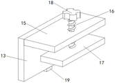
Fig. 2 is a schematic structural diagram of a pressing assembly in a positioning and pressing device for machining mechanical parts.
Fig. 3 is a schematic structural diagram of a guide assembly in a positioning and pressing device for machining mechanical parts.
The device comprises 11 parts of an operation table, 12 parts of supporting legs, 13 parts of a mounting plate, 14 parts of a hydraulic rod, 15 parts of a fixing plate, 16 parts of a threaded rod, 17 parts of a pressing plate, 18 parts of a knob, 19 parts of a guide block, 20 parts of a sliding chute, 21 parts of a sliding rod, 22 parts of a fixing frame, 23 parts of a guide roller, 24 parts of a limiting block and 25 parts of a spring.
Detailed Description
The technical solutions in the embodiments of the present invention will be clearly and completely described below with reference to the drawings in the embodiments of the present invention, and it is obvious that the described embodiments are only a part of the embodiments of the present invention, and not all of the embodiments. All other embodiments, which can be derived by a person skilled in the art from the embodiments given herein without making any creative effort, shall fall within the protection scope of the present invention.
Example 1
Referring to fig. 1 to 3, in an embodiment of the present invention, a positioning and compressing apparatus for machining a mechanical part includes an operation table 11 and supporting legs 12, wherein hydraulic rods 14 are symmetrically disposed at two ends of the top of the operation table 11, an output end of each hydraulic rod 14 is connected to an installation plate 13, and a compressing assembly and a guiding assembly are disposed on the installation plate 13;
the pressing assembly is used for fixing a part and comprises a fixing plate 15 which is arranged on the top of the mounting plate 13 and far away from one side of the hydraulic rod 14, a threaded rod 16 which is in threaded fit with the fixing plate 15 is arranged on the fixing plate 15, one end of the threaded rod 16 penetrates through the fixing plate 15 and is connected with a pressing plate 17, and a knob 18 is arranged at one end of the threaded rod 16 far away from the pressing plate 17.
The direction subassembly makes the part be convenient for remove after being compressed tightly, includes that a plurality of slides set up in mounting panel 13 bottom and run through mounting panel 13's slide bar 21, the one end that hydraulic stem 14 was kept away from to slide bar 21 is provided with mount 22, it is provided with guide roll 23 to rotate on the mount 22, and after the part was fixed, be convenient for remove or adjust the position of part in the direction with the extending direction vertically of hydraulic stem, the practicality is strong.
The one end that the guide roll 23 was kept away from to slide bar 21 is provided with the stopper 24 that prevents slide bar 21 and drop, the external diameter of stopper 24 is greater than slide bar 21's external diameter, the one end outside cover that slide bar 21 is close to mount 22 is equipped with spring 25, spring 25 one end is connected with mount 22, and its one end of keeping away from mount 22 is connected with mounting panel 13, and the guide roll can all the time with part side butt under the effect of slide bar and spring, can prevent that the position of part from taking place the skew in the extending direction of hydraulic stem.
The mounting panel 13 bottom is provided with guide block 19, set up the spout 20 with guide block 19 matching on the operation panel 11, can improve the stability of mounting panel at the removal in-process through the cooperation of guide block and spout, prevent that the direction from taking place the skew.
Example 2
The difference from example 1 is: the guide roll 23 and the pressing plate 17 are provided with buffering pads on the surfaces, so that the surfaces of parts can be protected, the parts are prevented from being abraded in the process of compressing and moving, and the practicability of the device is improved.
The working principle of the utility model is as follows:
place the part at the operation panel top during the operation, move the position of mounting panel through starting the hydraulic stem, the guide roll can all the time with part side butt under the effect of slide bar and spring, can prevent that the position of part from taking place the skew on the extending direction of hydraulic stem, can drive the threaded rod through rotating the knob and rotate, thereby it removes to drive the clamp plate, until clamp plate and part surface contact, be convenient for compress tightly fixedly not unidimensional part, it removes or adjusts the position of part in the extending direction vertically direction with the hydraulic stem to be convenient for through setting up of guide roll, moreover, the steam generator is simple in structure, and convenient for operation, therefore, the clothes hanger is strong in practicability.
It will be evident to those skilled in the art that the utility model is not limited to the details of the foregoing illustrative embodiments, and that the present invention may be embodied in other specific forms without departing from the spirit or essential attributes thereof.

Claims (6)

1.一种机械零部件加工用定位压紧装置,包括操作台(11)和支腿(12),其特征在于,所述操作台(11)顶部两端对称设置有液压杆(14),所述液压杆(14)的输出端连接有安装板(13),所述安装板(13)上设置有压紧组件和导向组件;1. A positioning and pressing device for machining mechanical parts, comprising an operating table (11) and an outrigger (12), characterized in that the top two ends of the operating table (11) are symmetrically provided with hydraulic rods (14), A mounting plate (13) is connected to the output end of the hydraulic rod (14), and a pressing component and a guiding component are arranged on the mounting plate (13); 所述压紧组件,包括设置在安装板(13)顶部远离液压杆(14)一侧的固定板(15),所述固定板(15)上设置有与其螺纹配合的螺纹杆(16),所述螺纹杆(16)一端贯穿固定板(15)并连接有压板(17),所述螺纹杆(16)远离压板(17)的一端设置有旋钮(18)。The pressing assembly includes a fixing plate (15) disposed on the top of the mounting plate (13) away from the hydraulic rod (14), and the fixing plate (15) is provided with a threaded rod (16) that is threadedly matched with the fixing plate (15), One end of the threaded rod (16) penetrates the fixing plate (15) and is connected with a pressure plate (17), and one end of the threaded rod (16) away from the pressure plate (17) is provided with a knob (18). 2.根据权利要求1所述的一种机械零部件加工用定位压紧装置,其特征在于,所述导向组件,使零件被压紧后便于移动,包括多个滑动设置在安装板(13)底端且贯穿安装板(13)的滑杆(21),所述滑杆(21)远离液压杆(14)的一端设置有固定架(22),所述固定架(22)上转动设置有导向辊(23)。2. A positioning and pressing device for machining mechanical parts according to claim 1, characterized in that, the guide assembly, which facilitates the movement of the parts after being pressed, comprises a plurality of slides arranged on the mounting plate (13) A sliding rod (21) at the bottom end and penetrating the mounting plate (13), the end of the sliding rod (21) away from the hydraulic rod (14) is provided with a fixing frame (22), and the fixing frame (22) is rotatably provided with a fixing frame (22). Guide roller (23). 3.根据权利要求2所述的一种机械零部件加工用定位压紧装置,其特征在于,所述滑杆(21)远离导向辊(23)的一端设置有防止滑杆(21)脱落的限位块(24),所述限位块(24)的外径大于滑杆(21)的外径。3. A positioning and pressing device for machining mechanical parts according to claim 2, characterized in that, one end of the sliding rod (21) away from the guide roller (23) is provided with a mechanism to prevent the sliding rod (21) from falling off. A limiting block (24), the outer diameter of the limiting block (24) is larger than the outer diameter of the sliding rod (21). 4.根据权利要求3所述的一种机械零部件加工用定位压紧装置,其特征在于,所述滑杆(21)靠近固定架(22)的一端外侧套设有弹簧(25),所述弹簧(25)一端与固定架(22)连接,其远离固定架(22)的一端与安装板(13)连接。4. A positioning and pressing device for machining mechanical parts according to claim 3, characterized in that, a spring (25) is sleeved on the outer side of one end of the sliding rod (21) close to the fixing frame (22), so One end of the spring (25) is connected with the fixing frame (22), and one end of the spring (25) away from the fixing frame (22) is connected with the mounting plate (13). 5.根据权利要求1所述的一种机械零部件加工用定位压紧装置,其特征在于,所述安装板(13)底部设置有导向块(19),所述操作台(11)上开设有与导向块(19)匹配的滑槽(20)。5 . The positioning and pressing device for machining mechanical parts according to claim 1 , wherein a guide block ( 19 ) is provided at the bottom of the mounting plate ( 13 ), and a guide block ( 19 ) is provided on the operating table ( 11 ). 6 . There is a chute (20) matching the guide block (19). 6.根据权利要求2所述的一种机械零部件加工用定位压紧装置,其特征在于,所述导向辊(23)和压板(17)表面均设置有缓冲垫。6 . The positioning and pressing device for machining mechanical parts according to claim 2 , wherein a buffer pad is provided on the surfaces of the guide roller ( 23 ) and the pressing plate ( 17 ). 7 .
CN202123272010.5U 2021-12-23 2021-12-23 Positioning and pressing device for machining mechanical parts Expired - Fee Related CN216859461U (en)

Priority Applications (1)

Application Number Priority Date Filing Date Title
CN202123272010.5U CN216859461U (en) 2021-12-23 2021-12-23 Positioning and pressing device for machining mechanical parts

Applications Claiming Priority (1)

Application Number Priority Date Filing Date Title
CN202123272010.5U CN216859461U (en) 2021-12-23 2021-12-23 Positioning and pressing device for machining mechanical parts

Publications (1)

Publication Number Publication Date
CN216859461U true CN216859461U (en) 2022-07-01

Family

ID=82148004

Family Applications (1)

Application Number Title Priority Date Filing Date
CN202123272010.5U Expired - Fee Related CN216859461U (en) 2021-12-23 2021-12-23 Positioning and pressing device for machining mechanical parts

Country Status (1)

Country Link
CN (1) CN216859461U (en)

Cited By (1)

* Cited by examiner, † Cited by third party
Publication number Priority date Publication date Assignee Title
CN116494170A (en) * 2023-06-29 2023-07-28 四川省嘉绮瑞航空装备有限公司 Positioning and clamping device for assembling front flap in airplane

Cited By (1)

* Cited by examiner, † Cited by third party
Publication number Priority date Publication date Assignee Title
CN116494170A (en) * 2023-06-29 2023-07-28 四川省嘉绮瑞航空装备有限公司 Positioning and clamping device for assembling front flap in airplane

Similar Documents

Publication Publication Date Title
CN214291918U (en) A turning and grinding machine for machining
CN203665141U (en) Cam self-locking clamping device
CN211759308U (en) A laser cutting machine splint device
CN210648578U (en) A kind of handicraft drilling device
CN204339328U (en) A kind of hold-down mechanism
CN211812666U (en) A cloth pressing device for automatic spreading
CN202547970U (en) Automatic slicing instrument of fiber
CN211123086U (en) A detection device for electrical automation equipment
CN109822418B (en) A case frame edging equipment for computer production
CN217319403U (en) Fixed table type press with automatic lifting platform
CN217551961U (en) A multi-angle grinding device for inner hole machining of roller sleeves
CN211757815U (en) Bending device is used in steel structure processing
CN211276793U (en) Cutting equipment for processing cylindrical rod
CN110341361B (en) An engraving machine workbench for gourd carving
CN207723550U (en) A kind of equipment of processing miniature workpiece
CN219403346U (en) A material stabilization mechanism
CN216504683U (en) Clamping device is used in metal product production and processing
CN209774356U (en) a clamping device
CN219255241U (en) Quick positioning mechanism of needle grinding machine
CN220698486U (en) Soldering tin machine for processing electronic products
CN207577582U (en) Anti- after a kind of processing of metal works collapses disconnecting device
CN219211388U (en) A multifunctional servo feeder
CN216096490U (en) A kind of drilling machine for compressor balance block processing
CN217252312U (en) Stamping device is used in machine part production and processing
CN221676800U (en) Metal processing polishing equipment with fixture

Legal Events

Date Code Title Description
GR01 Patent grant
GR01 Patent grant
CF01 Termination of patent right due to non-payment of annual fee

Granted publication date: 20220701

CF01 Termination of patent right due to non-payment of annual fee