SUMMERY OF THE UTILITY MODEL
In view of the above problems, the present application provides a battery assembling jig, which effectively improves the precision in the battery assembling process.
In a first aspect, the present application provides a battery assembly jig, comprising:
the battery cell support structure comprises a bottom plate, a plurality of battery cells and a plurality of supporting plates, wherein the bottom plate is provided with a supporting surface for supporting the plurality of battery cells, and the supporting surface is attached to a top cover of the battery cells;
the at least two groups of tightly-pushing assemblies surround the supporting surface for one circle and are connected with the bottom plate, and an accommodating space is formed between the at least two groups of tightly-pushing assemblies and the supporting surface and used for accommodating a plurality of battery cells;
the pressing piece is detachably connected with the bottom plate, at least part of the pressing piece and the supporting surface oppositely cover the top of the accommodating space, and the pressing piece is used for pressing the plurality of battery cells along the first direction;
the first direction is perpendicular to the support surface.
In the technical scheme of the embodiment of the application, the supporting surface and at least two groups of jacking components are arranged on the bottom plate and matched to realize the assembly of multiple electric cores, and the top cover of the electric core is attached to the supporting surface when the electric core is formed, so that the inverted assembly of the electric core can be realized, the flatness of a battery pole is ensured, the influence on subsequent welding is reduced, and the precision of the battery assembly process is greatly improved; the setting that compresses tightly the piece simultaneously makes electric core hold can be compressed tightly in both sides by compressing tightly piece and bottom plate after in the accommodation space, and then can cooperate tipping arrangement or frock to realize the product and be the steady upset of battery, and the battery of being convenient for to assemble the completion separates the drawing of patterns with battery assembly jig.
In some embodiments, the battery assembling jig further includes a plurality of partition plates, the plurality of partition plates are disposed on the supporting surface at intervals along the second direction and extend along the third direction, and a sub-accommodating space is formed between adjacent partition plates to accommodate the plurality of battery cells along the third direction;
the second direction and the third direction are respectively the length and width directions of the base plate.
Above-mentioned mode of setting up makes the setting through the baffle form the separation between adjacent electric core, is favorable to guaranteeing the clearance positioning requirement of electric core to sub accommodation space between the adjacent baffle can follow a plurality of electric cores of third direction holding, makes the electric core that the disclosed battery assembly jig of this embodiment can hold be the form of multirow multiseriate, and then realizes the equipment of jumbo size battery or battery module.
In some embodiments, the thickness of the separator is 1.2mm to 1.3 mm. The space between the adjacent electric cores along the second direction is effectively ensured, so that the gap positioning requirement is met.
In some embodiments, the aforementioned battery assembly jig further comprises a plurality of tensioning assemblies;
a plurality of tensioning assemblies are distributed along the circumferential direction of the supporting surface at intervals, and the tensioning assemblies are detachably connected with the pressing piece and used for tensioning the pressing piece along the first direction. When making the water-cooling board gland that will coat with the heat conduction glue on electric core, taut subassembly can be through compressing tightly the piece with water-cooling board pull-down, effectively evenly spreads out the heat conduction glue of high viscosity, reaches the moulding area and the gum layer thickness of technological requirement.
In some embodiments, the take-up assembly includes a power component and a connector;
the power part is arranged on the bottom plate, one end of the connecting piece vertically penetrates through the bottom plate to be connected with the power part, and the other end of the connecting piece is connected with the pressing piece. The power part is connected with the pressing part through the connecting part, applies force to the pressing part through the connecting part, and is tensioned towards the lower part of the bottom plate, so that the water cooling plate can be pressed; the connecting piece is detachably connected with the pressing piece.
In some embodiments, the jacking assembly comprises a driving part, a pressure plate and a first limiting assembly;
the pressing plate is vertical to the supporting surface, and the driving part is connected with the pressing plate and used for adjusting the relative position of the pressing plate on the jacking assembly;
the first limiting assembly is arranged on the pressing plate along the first direction and used for movably mounting an end plate or a side plate of the battery. Through the arrangement, the jacking assembly can drive the end plates or the side plates of the battery to jack tightly to the circumferential edge of the battery core, so that the welding assembly of the adjacent end plates and the adjacent side plates is realized, and then the assembly of the battery is completed; the driving part can drive the pressing plate with the end plate or the side plate to reciprocate along the direction parallel to the supporting surface so as to match with the tight jacking assembly and the separation demoulding of the battery; the first limiting part is arranged along the first direction, so that the end plate or the side plate can be installed on the pressing plate and cannot fall to the supporting surface.
In some embodiments, the jacking assembly further comprises a second limiting assembly;
the second limiting assembly is arranged on the pressing plate along the direction of the parallel supporting surface and used for limiting the end plate or the side plate along the direction of the parallel supporting surface. Can guarantee through the spacing subassembly of second that end plate or curb plate carry out the edge butt joint with adjacent curb plate or end plate in the position of parallel bearing surface direction, effectively guarantee that it can be comparatively accurate.
In some embodiments, the first limit component comprises a fixed block and a movable piece;
the fixed block sets up in the one end that the clamp plate deviates from the holding surface, and the moving part telescopically sets up in the one end of clamp plate towards the holding surface, and the moving part can follow the reciprocating of first direction and stretch out and draw back. In order to be adapted to not unidimensional end plate or curb plate to simplify the installation of end plate or curb plate and clamp plate, first spacing subassembly includes fixed block and moving part, and the fixed block forms the benchmark end in the clamp plate top, and the moving part forms the regulation end below the clamp plate, when needing installation end plate or curb plate, draws back the moving part earlier and lets the position, and end plate or curb plate of packing into, then the moving part makes to the fixed block shrink in order to press from both sides tight end plate or curb plate.
In some embodiments, the moveable member comprises a first elbow clip, a mounting plate, a stop plate, and a resilient member;
the mounting plate is fixedly connected with the pressing plate;
the limiting plate sets up along first direction and mounting panel interval, and mounting panel and limiting plate are contradicted respectively at the both ends of elastic component, and mounting panel and limiting plate are connected simultaneously to first elbow clamp for adjust the distance between limiting plate and the mounting panel. The adjustment to the limiting plate position is realized through the setting of first elbow clamp, accomplishes stepping down to end plate or curb plate installation.
In some embodiments, the moveable member further comprises a guide post;
the guide post is arranged between the mounting plate and the limiting plate in a penetrating mode, and the elastic piece is sleeved outside the guide post. The guide post provides the direction for the compression of elastic component or resume deformation, avoids the elastic component to take place crooked or buckle by compression or resume deformation in-process, influences the elasticity performance of moving part.
In some embodiments, the second stop assembly comprises a second elbow clip, a rail assembly, and a compression block;
the guide rail assembly is parallel to and connected with the end part of the parallel supporting surface of the pressure plate;
the pressing block vertical pressing plate and the guide rail assembly are arranged at intervals, and the second elbow clamp is connected with the pressing block and the guide rail assembly simultaneously along the direction parallel to the supporting surface and used for adjusting the distance between the pressing block and the pressing plate generated by the movement of the pressing block along the guide rail assembly. The end plate or the side plate can be conveniently arranged on the jacking assembly, and a welding gap can be effectively guaranteed.
In some embodiments, the drive is a rotary worm gear or screw. The driving part is set as a screw rod, so that the compression plate can be easily stretched; the driving part is set to rotate the worm gear, so that the strength of the driving part can be effectively improved, and the large-size battery is assembled correspondingly and has good benefits; the driving part of at least one group of tightening assemblies in at least two groups of tightening assemblies is arranged to be a rotating worm gear.
In some embodiments, there are four sets of jacking assemblies;
wherein two sets of tight subassemblies in top set up along the second direction relatively, and the tight subassembly in other two sets of tops sets up along the third direction relatively for respectively along the length and the width direction tight a plurality of electric cores of bottom plate. For square shell electricity core, set up two sets of tight subassemblies in top and set up the curb plate that is used for pushing up tight battery relatively along the second direction in this embodiment, the tight subassembly in remaining two sets of tops sets up the end plate that is used for pushing up tight battery relatively along the third direction, forms the square shell framework of battery through the welded connection between end plate and the curb plate.
In some embodiments, the compression member includes a compression plate and a connection portion;
the pressure strip comprises a foam layer, an insulating layer and a reinforcing layer which are sequentially stacked in the reverse direction of the first direction;
the connecting parts are distributed at intervals along the circumferential direction of the foam layer and are matched with the tensioning assembly. The pressing plate is used for pressing the water cooling plate towards the direction of the bottom plate, and the heat conducting glue on the water cooling plate is uniformly spread to bond the battery cell and the water cooling plate, so that water cooling heat dissipation is realized; wherein, what be close to the water-cooling board is the cotton layer of bubble, plays the cushioning effect, avoids compressing tightly the damage of in-process, prolongs the life of pressure strip.
In some embodiments, the pressing member further comprises a reinforcing rib disposed on a side of the reinforcing layer facing away from the foam layer. The strengthening rib help improving the intensity that compresses tightly the piece, can effectually compress tightly the water-cooling board to the powerful tension of taut subassembly, and the structural strength of avoiding the pressure strip is lower, can't bear the tension of taut subassembly.
In some embodiments, the aforementioned battery assembling jig further includes a reinforcing bracket disposed on a side of the bottom plate away from the supporting surface. The reinforcing bracket is used for reinforcing the strength of the bottom plate below the bottom plate, namely the overall strength of the battery assembling jig.
The foregoing description is only an overview of the technical solutions of the present application, and the present application can be implemented according to the content of the description in order to make the technical means of the present application more clearly understood, and the following detailed description of the present application is given in order to make the above and other objects, features, and advantages of the present application more clearly understandable.
Detailed Description
Embodiments of the present invention will be described in detail below with reference to the accompanying drawings. The following examples are merely used to more clearly illustrate the technical solutions of the present application, and therefore are only examples, and the protection scope of the present application is not limited thereby.
Unless defined otherwise, all technical and scientific terms used herein have the same meaning as commonly understood by one of ordinary skill in the art to which this application belongs; the terminology used herein is for the purpose of describing particular embodiments only and is not intended to be limiting of the application; the terms "including" and "having," and any variations thereof, in the description and claims of this application and the description of the above figures are intended to cover non-exclusive inclusions.
In the description of the embodiments of the present application, the technical terms "first", "second", and the like are used only for distinguishing different objects, and are not to be construed as indicating or implying relative importance or implicitly indicating the number, specific order, or primary-secondary relationship of the technical features indicated. In the description of the embodiments of the present application, "a plurality" means two or more unless specifically defined otherwise.
Reference herein to "an embodiment" means that a particular feature, structure, or characteristic described in connection with the embodiment can be included in at least one embodiment of the application. The appearances of the phrase in various places in the specification are not necessarily all referring to the same embodiment, nor are separate or alternative embodiments mutually exclusive of other embodiments. It is explicitly and implicitly understood by one skilled in the art that the embodiments described herein may be combined with other embodiments.
In the description of the embodiments of the present application, the term "and/or" is only one kind of association relationship describing an associated object, and means that three relationships may exist, for example, a and/or B, and may mean: there are three cases of A, A and B, and B. In addition, the character "/" herein generally indicates that the former and latter related objects are in an "or" relationship.
In the description of the embodiments of the present application, the term "plurality" refers to two or more (including two), and similarly, "plural sets" refers to two or more (including two), and "plural pieces" refers to two or more (including two).
In the description of the embodiments of the present application, the terms "center", "longitudinal", "lateral", "length", "width", "thickness", "up", "down", "front", "back", "left", "right", "vertical", "horizontal", "top", "bottom", "inner", "outer", "clockwise", "counterclockwise", "axial", "radial", "circumferential", and the like, indicate the directions or positional relationships indicated in the drawings, and are only for convenience of description of the embodiments of the present application and for simplicity of description, but do not indicate or imply that the referred device or element must have a specific direction, be constructed and operated in a specific direction, and thus, should not be construed as limiting the embodiments of the present application.
In the description of the embodiments of the present application, unless otherwise explicitly stated or limited, the terms "mounted," "connected," "fixed," and the like are used in a broad sense, and for example, may be fixedly connected, detachably connected, or integrated; mechanical connection or electrical connection is also possible; they may be directly connected or indirectly connected through intervening media, or may be connected through the use of two elements or the interaction of two elements. The specific meanings of the above terms in the embodiments of the present application can be understood by those of ordinary skill in the art according to specific situations.
At present, the application of power batteries is more and more extensive from the development of market conditions. The power battery is not only applied to energy storage power supply systems such as hydraulic power, firepower, wind power and solar power stations, but also widely applied to electric vehicles such as electric bicycles, electric motorcycles, electric automobiles and the like, and multiple fields such as military equipment and aerospace; with the continuous expansion of the application field of the power battery, the market demand is also continuously expanding.
The inventor notices that in the new energy battery industry, no matter what shape of battery is, the external frame structure is enclosed by the clamp end plate, the side plate 7 and the water cooling plate to carry out series-parallel connection containing on a plurality of battery cells, and finally the battery is assembled to form a complete module structure; the water cooling plate is arranged at the bottom of the clamp as a bearing device of the battery cell and is bonded with the battery cell by the prior art personnel mostly, and then the end plate and the side plate 7 are clamped tightly by the clamp at the periphery of the side edge to be welded and assembled to form a main frame structure. However, the battery cell assembled in the above manner is normally installed on the water cooling plate, the uniformity of the final height of the battery cell pole column cannot be guaranteed in a stepping mode, and the formed frame structure cannot be matched with the overturning operation of the subsequent process.
In order to solve the problem that the precision of the battery assembling process of the existing clamp is low, the applicant researches and discovers that the battery assembling process can be realized by inversely installing the battery core and finally overturning the battery core after the battery core is completely assembled to perform welding and separation demolding, so that the height uniformity of the battery core pole is ensured, the flatness of the pole is greatly improved, and the influence of the height difference of the pole in the early stage on the follow-up welding is effectively reduced.
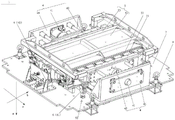
Based on the above consideration, in order to solve the problem that the existing clamp has low precision in the battery assembling process, the inventor designs a battery assembling clamp 1 through intensive research, referring to fig. 1, an inverted datum plane in the assembling process is provided for a top cover of a battery core 3 by arranging a supporting surface 21 on a bottom plate 2, and then the planeness of a pole can be effectively ensured; the tight-jacking groups of the end plates or the side plates 7 are realized by arranging at least two groups of tight-jacking assemblies 4 so as to form the peripheral frame of the battery.
Meanwhile, in the battery assembling jig 1, a pressing piece 5 is further arranged, so that a water cooling plate (not shown in the figure) can be assembled finally, and the water cooling plate can be pressed against the battery cell 3 towards the bottom plate 2, so that the battery cell 3 is clamped in the up-down direction, and stable overturning welding and separation demoulding in cooperation with overturning equipment or a tool are realized; additionally, the heat-conducting glue between the water cooling plate and the electric core 3 can be effectively and uniformly spread out, and the glue pressing thickness and the glue pressing area of the process requirement are met.
The battery assembling jig 1 disclosed in the embodiment of the present application can be used in a lithium battery without limitation, and when a complete battery is assembled by a plurality of battery cells 3 or battery cells, the battery assembling jig 1 provided by the present embodiment performs flip-chip assembly, flip-chip welding and separation demolding on the plurality of battery cells 3, thereby ensuring the assembly accuracy of a final battery product. The battery assembled by the battery assembling jig 1 disclosed by the application can be used for forming a power supply system of the electric equipment, so that the assembly precision of the battery in the electric equipment and the electric system is improved.
According to some embodiments of the present application, referring to fig. 1, fig. 2 and fig. 3, the present application provides a battery assembling jig 1, which includes a base plate 2, at least two sets of tightening assemblies 4 and a pressing member 5; the bottom plate 2 is provided with a supporting surface 21 for supporting the plurality of battery cells 3, and the supporting surface 21 is attached to the top covers of the battery cells 3;
the at least two groups of jacking assemblies 4 surround the supporting surface 21 for one circle and are connected with the bottom plate 2, and the at least two groups of jacking assemblies 4 and the supporting surface 21 form an accommodating space for accommodating a plurality of battery cells 3;
the pressing piece 5 is detachably connected with the bottom plate 2, and at least part of the pressing piece 5 and the supporting surface 21 cover the top of the accommodating space oppositely and are used for pressing the plurality of battery cells 3 along the first direction a;
the first direction a is perpendicular to the support surface 21.
The bottom plate 2 is a rigid structure, and is provided with a supporting surface 21, the supporting surface 21 is a flat surface, the supporting surface 21 may be a part of the upper surface of the bottom plate 2, or as shown in fig. 4, an additional plate body is additionally provided on the bottom plate 2 to form the supporting surface 21.
The jacking component 4 is a component which can movably mount an end plate (not shown in the figure) or a side plate 7 and can drive the end plate or the side plate 7 to jack or separate towards the electric core 3; the jacking assembly 4 is detachably arranged on the bottom plate 2, for example: connecting by bolts; the jacking assembly 4 surrounds the supporting surface 21 for a circle and is used as a side wall to be matched with the supporting surface 21 to form a plurality of accommodating spaces of the battery cells 3; the number of tightening units 4 may be determined according to the shape of the battery, for example: when the battery is cylindrical, the number of the jacking components 4 can be two groups, the part of each group of jacking components 4 for installing the end plate or the side plate 7 is of a semicircular structure, and the two groups of jacking components 4 are oppositely arranged and can be enclosed into a circular shape corresponding to the cylindrical shape of the battery; another example is: when the battery is in a cylindrical or triangular prism shape, the number of the tightening assemblies 4 can be three groups, the three groups of tightening assemblies 4 are uniformly distributed along the circumferential direction of the supporting surface 21, the part of each group of tightening assemblies 4 for installing the end plate or the side plate 7 is in an arc-shaped structure or a sharp-angle-shaped structure, and the three groups of tightening assemblies 4 are oppositely arranged and can be enclosed into a circular or triangular cylindrical or triangular prism shape corresponding to the battery; for another example: when the shape of the battery is square, the number of the jacking components 4 can be four groups, the four groups of jacking components 4 respectively correspond to one side of the square, the part of each group of jacking components 4 for installing the end plate or the side plate 7 is of a planar plate-shaped structure, and the four groups of jacking components 4 are oppositely arranged so as to form the square corresponding to the battery. It can be understood that: the tightening unit 4 necessarily has a mounting seat 45, and is detachably connected to the base plate 2 through the mounting seat 45.
The end plates and the side plates 7 are both rigid plate-shaped structures, correspond to square batteries, and are used for processing the top cover and the bottom of the batteries, the end plates are arranged on the larger side of the batteries to serve as outer side frames, and the side plates 7 are arranged on the smaller side of the batteries to serve as outer side frames; the end plates need to bear the expansion force in the battery, so the end plates need to have certain strength and can be arranged in a cast aluminum mode; the side plates 7 are mostly of a C-shaped configuration.
Compress tightly piece 5 and be the rigid structure, it is connected with 2 detachable of bottom plate, it can take off when setting up electric core 3, install when installation water-cooling board (not shown in the figure), with compressing tightly water-cooling board on electric core 3 to 2 directions of bottom plate, and bond water-cooling board and electric core 3 each other through heat-conducting glue (not shown in the figure), guarantee that a plurality of electric cores 3 all are in the state that is compressed tightly about the upper and lower in battery assembly jig 1, and then can cooperate tipping arrangement to carry out steady upset.
The water-cooling board is the heat management system of battery, and it bonds each other with electric core 3 through heat-conducting glue, and then can export the heat of electric core 3 output through heat-conducting glue and carry out water-cooling heat dissipation.
The first direction a is perpendicular to the supporting surface 21, and in this embodiment, referring to fig. 1 and fig. 4, is a direction perpendicular to the supporting surface 21 from top to bottom in the drawing, that is, a direction in which the upper surface of the bottom plate 2 points to the lower surface.
The supporting surface 21 and at least two groups of jacking components 5 are arranged on the bottom plate 2 and matched to realize the assembly of the multi-battery-core 3 battery, and the top cover of the battery core 3 is attached to the supporting surface 21 when the battery core 3 is formed, so that the inverted assembly of the battery core 3 can be realized, the flatness of a battery pole is ensured, the influence on subsequent welding is reduced, and the precision of the battery assembly process is greatly improved; the setting that compresses tightly piece 5 simultaneously makes electric core 3 hold can be compressed tightly in both sides by compressing tightly piece 5 and bottom plate 2 in the accommodation space after, and then can cooperate tipping arrangement or frock to realize the steady upset of product promptly battery, and the battery of the equipment completion of being convenient for separates the drawing of patterns with battery assembly jig 1.
According to some embodiments of the present application, optionally, referring to fig. 4 and 5, the battery assembling jig 1 further includes a plurality of partition plates 22, the plurality of partition plates 22 are disposed at intervals on the supporting surface 21 along the second direction b and extend along the third direction c, and a sub-accommodating space is formed between adjacent partition plates 22 to accommodate the plurality of battery cells 3 along the third direction c;
the second direction b and the third direction c are respectively the length and width directions of the base plate 2.
The partition boards 22 are rigid flat plate structures, multiple columns of sub-accommodation spaces are formed in the bottom plate 2 by the arrangement of the partition boards 22, and each column of sub-accommodation space can accommodate multiple battery cells 3, and then the battery assembling jig 1 provided in this embodiment can realize the assembly of multiple rows and multiple columns of battery cells 3 shown in fig. 5, compared with the single row of multiple battery cells in the prior art, the battery that can be assembled by the battery assembling jig 1 in this embodiment is a battery with a larger size, for example, 1400mm × 800mm 180mm and above, it can be understood that the battery assembling jig 1 in this embodiment can also be used for assembling a single row of multiple battery cells, that is, a battery with a small size. The arrangement of the partition plate 22 can form an isolation and positioning structure between adjacent battery cells 3 along the second direction b, thereby effectively ensuring the gap assembly between the battery cells 3. Referring to fig. 5, the second direction b and the third direction c are a length direction and a width direction of the base plate 2, i.e., a left-upper-to-right-lower direction and a left-lower-to-right-upper direction in the drawing, respectively.
The separation is formed between the adjacent electric cores 3 through the arrangement of the partition plates 22, so that the gap positioning requirement of the electric cores 3 is favorably ensured, and the problem of low precision caused by manual interval arrangement of the electric cores 3 for interval adjustment is avoided; and the sub-accommodation space between the adjacent partition plates 22 can accommodate a plurality of battery cells 3 along the third direction c, so that the battery cells 3 that can be accommodated by the battery assembling jig 1 disclosed in this embodiment are in a form of multiple rows and multiple columns, thereby realizing the assembly of a large-size battery or a battery module.
According to some embodiments of the present application, optionally, with reference to fig. 4, the spacer has a thickness of 1.2mm to 1.3 mm; the space between the adjacent electric cores 3 along the second direction b can be effectively ensured, so that the space meets the gap positioning requirement, and after the battery is assembled, separated and demoulded, a space is formed between the electric cores 3 for absorbing the expansion force of the battery; the height of the partition 22 is not limited to a great extent and may be set as desired, for example: 15 mm.
According to some embodiments of the present application, optionally, with reference to fig. 1 to 4, the battery assembly jig 1 further comprises a number of tensioning assemblies 6;
the plurality of tensioning assemblies 6 are distributed at intervals along the circumferential direction of the supporting surface 21, and the plurality of tensioning assemblies 6 are detachably connected with the pressing piece 5 and used for tensioning the pressing piece 5 along the first direction a.
The tensioning assembly 6 is a rigid structure formed by a plurality of structural members, is arranged on the bottom plate 2 along the circumferential direction of the supporting surface 21, and can provide force and a force application point for pressing the pressing member 5 to the bottom plate 2; when the water cooling plate needs to be pressed and bonded, the tensioning assembly 6 is connected with the pressing piece 5, and the pressing piece 5 is tensioned towards the bottom plate 2, so that the water cooling plate coated with the heat-conducting glue is pressed forcibly; when the battery is assembled again, the tension assembly 6 and the pressing member 5 are disconnected from each other. The number of tensioning elements 6 is not described in any greater detail here and may be as many as 4 circumferential groups as shown in fig. 4, or more, depending on how much tension is required.
Taut subassembly 6 and the cooperation that compresses tightly 5 can be with the coating when having the water-cooling plate gland of heat conduction glue on electric core 3, taut subassembly 5 can be through compressing tightly 5 with the water-cooling plate drop-down, effectively evenly spread out the heat conduction glue of high viscosity, reach the moulding area and the gum layer thickness of technological requirement.
According to some embodiments of the present application, optionally, with reference to fig. 1 to 4, the tightening assembly 6 comprises a power member (not shown in the figures) and a connecting piece 61;
power component sets up in bottom plate 2, and connecting piece 61 one end is passed bottom plate 2 perpendicularly and is connected with power component, and the other end with compress tightly a 5 and be connected, sets up power component in the below of bottom plate 2 in this embodiment, and then can directly draw and press chucking spare 5.
The power part (not shown) is a power part for providing tension, and may be a cylinder, and a piston of the cylinder is connected with the connecting member 61 to apply downward tension to the pressing member 6 through the connecting member 61.
The connecting member 61 has a structure with connecting ends at two ends, such as a Y-shaped joint shown in fig. 4, the branched end faces the upper side of the base plate 2, and can be detachably connected with the pressing member 5 through a bolt, and the single end faces the lower side of the base plate for connecting with a power component (not shown in the figure).
The power part (not shown in the figure) and the pressing piece 5 are connected through the connecting piece 61, and the power part applies force to the pressing piece 5 through the connecting piece 61 to pull the pressing piece to the lower part of the bottom plate 2, so that the pressing piece can press the water cooling plate.
According to some embodiments of the present application, optionally, referring to fig. 6, the tightening assembly 4 includes a driving portion 41, a pressing plate 42, and a first limiting assembly 43;
the pressing plate 42 is vertical to the supporting surface 21, and the driving part 41 is connected with the pressing plate 42 and used for adjusting the relative position of the pressing plate 42 on the jacking assembly 4;
the first position-limiting component 43 is disposed on the pressing plate 42 along the first direction a, and is used for movably mounting the end plate or the side plate 7 of the battery.
The driving part 41 is the moving power of the pressing plate 42, and the driving part 41 can drive the pressing plate 42 with the end plate or the side plate 7 to reciprocate along the direction parallel to the supporting surface 21 so as to match the abutting assembly and the separation demoulding of the battery. The drive 41 may be a rotating worm gear or a screw; when the object to be tightly pressed by the pressing component 4 is an end plate, the driving part 41 can be set as a rotary worm gear, the strength of the driving part 41 can be effectively improved by the rotary worm gear, and the large-size battery is assembled correspondingly and has good benefits; when the side plate 7 is the object to be pressed by the pressing unit 4, the driving unit 41 may be a screw rod, which can easily extend and contract the pressing plate 42.
The pressing plate 42 is a carrier for mounting the end plate or the side plate 7, the pressing plate 42 is a rigid structure, and the shape of the pressing plate 42 depends on the shape of the end plate or the side plate 7 of the battery, which is not described in detail herein.
The first limiting component 43 is disposed on the pressing plate 2 along the first direction a, and can limit the position of the end plate or the side plate 7 in the first direction a.
Through the arrangement, the jacking component 4 can drive the end plates or the side plates 7 of the battery to jack tightly to the circumferential edge of the battery core 3, so that the adjacent end plates and the side plates 7 are welded and assembled, and then the battery is assembled; wherein, the driving part 41 can drive the pressing plate 42 with the end plate or the side plate 7 to reciprocate along the direction parallel to the supporting surface 21 so as to match with the abutting assembly and the separation demoulding of the battery; the first stop 43 ensures that the end plate or side plate 7 can be mounted on the pressure plate 42 without falling to the support surface 21.
According to some embodiments of the present application, optionally, with reference to fig. 6, the first limiting assembly 43 includes a fixed block 431 and a movable member 432;
the fixed block 431 is disposed at an end of the pressing plate 42 away from the supporting surface 21, the movable member 432 is telescopically disposed at an end of the pressing plate 42 facing the supporting surface 21, and the movable member 432 is capable of extending and retracting along a first direction.
The fixing block 431 is a rigid structure, and is disposed at the upper end of the pressing plate 42 and extends along the parallel supporting surface 21 in a direction away from the driving portion 41, so as to form a fixing stopper at the upper end of the pressing plate 42, and provide a reference for the installation of the end plate or the side plate 7.
The movable member 432 is disposed at the lower end of the pressing plate 42, the movable member 432 can reciprocate in a direction away from or close to the fixed block 431, when the end plate or the side plate 7 is mounted or separated, the movable member 432 needs to move in a direction away from the fixed block 431 to move to a certain extent, so that the end plate or the side plate 7 can enter (separate) between the fixed block 431 and the movable member 432, and the movable member 432 is reset after entering (separating) to clamp and limit the end plate or the side plate 7.
The fixed block 431 forms a reference end above the pressing plate 42, the movable member 432 forms an adjusting end below the pressing plate 42, and when the end plate or the side plate 7 needs to be installed, the movable member 432 is firstly pulled open to give way and is installed in the end plate or the side plate 7, so that the movable member 432 contracts towards the fixed block 431 to clamp the end plate or the side plate 7.
According to some embodiments of the present application, optionally with reference to fig. 6 and 7, the movable member 432 includes a first toggle clamp 4321, a mounting plate 4322, a limiting plate 4323, and a resilient member 4324;
the mounting plate 4322 is fixedly connected with the pressure plate 42;
the limiting plate 4323 is spaced from the mounting plate 4322 along the first direction a, two ends of the elastic member 4324 respectively abut against the mounting plate 4322 and the limiting plate 4323, and the first elbow clamp 4321 is simultaneously connected to the mounting plate 4322 and the limiting plate 4323, so as to adjust a distance between the limiting plate 4323 and the mounting plate 4322.
The mounting plate 4322 and the limiting plate 4323 are both rigid structures, and the mounting plate 4322 is fixedly connected with the pressing plate 42 to form a stable connecting end of the movable part 432; the limiting plate 4323 is used for generating relative movement relative to the mounting plate 4322 and is used for clamping the end plate or the side plate 7 by matching with the fixing block 431.
The elastic element 4324 has elasticity, and is capable of deforming and generating a force for restoring the deformation, and in the embodiment, the elastic element 4324 is disposed between the mounting plate 4322 and the limiting plate 4323, so as to realize the relative movement and the resetting of the limiting plate 4323 relative to the mounting plate 4322 or the pressing plate 42. The elastic member 4324 may be a spring or a rubber member.
The first elbow clip 4321 is a driving member, and the first elbow clip 4321 is connected to the mounting plate 4322 and the limiting plate 4323 at the same time, referring to fig. 7, the first elbow clip 4321 is manually pulled down or lifted up to make the limiting plate 4323 move downward or upward to stretch or compress the elastic member 4324, and the first elbow clip 4321 can be kept in a current state after being pulled down or lifted up, and the first elbow clip 4321 can be easily understood by those skilled in the art and can perform its functions, which will not be described herein in detail.
Referring to fig. 8, when the tightening assembly 4 is correspondingly installed with the side plate 7, the first limiting assembly 43 is supported at two ends of the side plate 7 along the first direction a inside the side plate 7 due to the C-shaped plate structure of the side plate 7; referring to fig. 7 and 8, the first elbow clamp 4321 is lifted up to lift the limit plate 4323 to reduce the distance between the limit plate 4323 and the fixed block 431, so that the two ends of the side plate 7 are covered outside the fixed block 431 and the limit plate 4323, at this time, the elastic element 4234 is in a compressed state, and the first elbow clamp 4321 is pulled down, so that the elastic element 4324 is deformed to generate a force in a direction downward, i.e., toward the bottom plate 2, and thus, the lower edge of the side plate 7 is supported downward, thereby ensuring the stable installation of the side plate 7 along the first direction a; it is understood that, at this time, the limit plate 4323 may have a bent portion to fit the bent lower edge of the side plate 7. In contrast, when the tightening assembly 4 is correspondingly provided with an end plate (not shown in the drawings), since the end plate is a flat plate, the control manner of the movable member 432 in this embodiment is opposite to that described above, first the first toggle clamp 4321 is pulled downward, the limiting plate 4323 is pulled downward to increase the distance between the limiting plate 4323 and the fixed block 431, so as to place the end plate between the fixed block 431 and the limiting plate 4323, at this time, the elastic member 4234 is in a stretched state, and then the first toggle clamp 4321 is lifted upward, so that the elastic member 4324 recovers to deform to generate a force upward, i.e., in a direction opposite to the direction of the bottom plate 2, thereby lifting the lower edge of the end plate upward, and thus ensuring stable installation of the end plate along the first direction a.
The position of the limiting plate 4323 is adjusted by the arrangement of the first elbow clip 4321, and abdication of the installation process of the end plate or the side plate 7 is completed.
According to some embodiments of the present application, optionally, with reference to fig. 6, moveable member 432 further includes a guide post 4325;
the guide column 4325 is inserted between the mounting plate 4322 and the limiting plate 4323, and the elastic member 4324 is sleeved outside the guide column 4325.
The guide columns 4325 are rigid linear columns that provide a guide for the deformation direction of the elastic members 4324.
The guide columns 4325 provide guidance for the compression or recovery deformation of the elastic members 4324, so as to prevent the elastic members 4324 from being bent or bent in the compression or recovery deformation process to affect the expansion and contraction performance of the movable member 432.
According to some embodiments of the present application, optionally, referring to fig. 9, the tightening assembly 4 further includes a second limiting assembly 44;
the second limiting component 44 is disposed on the pressing plate 2 along the direction parallel to the supporting surface 21, and is used for limiting the end plate or the side plate 7 along the direction parallel to the supporting surface 21.
The second position-limiting element 44 is arranged on the pressure plate 2 along a direction parallel to the support surface 21, for example: along a second direction b, a third direction c or other 21 direction parallel to the support surface; the second limiting component 44 can play a limiting role in the second direction b, the third direction c or other directions 21 parallel to the supporting surface, so that the end plates or the side plates 7 can be mounted and separated, and the problem that the end parts between the adjacent end plates or the adjacent side plates 7 do not correspondingly influence welding is avoided.
The position of the end plate or the side plate 7 in the direction parallel to the supporting surface 21 can be ensured through the second limiting component 44, and edge butt joint with the adjacent side plate 7 or the end plate can be effectively ensured.
According to some embodiments of the present application, optionally, referring to fig. 6, the second limiting component 44 is a fixed structure, the second limiting component 44 includes an L-shaped pressing block 441, the pressing block 441 is disposed at an end portion of the pressing plate 42 parallel to the supporting surface 21, one end of the pressing plate 42 parallel to the end portion is perpendicular to the pressing plate 42 to form a limiting end, and the limiting end is used for limiting the end plate or the side plate 7 in a direction parallel to the supporting surface 21.
According to some embodiments of the present application, optionally, referring to fig. 9 and 10, the second limiting member 44 is a retractable structure, the second limiting member 44 includes a second elbow clip 442, a guide rail member 443, and a compression block 441;
the guide rail assembly 443 is parallel to and connected to the end of the platen 42 parallel to the support surface 21;
the pressing block 441 is spaced apart from the guide rail assembly 443 perpendicularly to the pressing plate 42, and the second toggle clamp 442 is coupled to both the pressing block 441 and the guide rail assembly 443 along a direction parallel to the supporting surface 21 for adjusting a distance between the pressing block 441 and the pressing plate 42 along the guide rail assembly 443.
The pressing block 441 is of an L-shaped rigid structure, one end of the pressing block is parallel to the pressing plate 42, the other end of the pressing block is perpendicular to the pressing plate 42 to form a limiting end, and the pressing block 441 can be made of copper and can achieve the effect of separating welding slag and dissipating heat quickly in the welding process.
The guide assembly 443, referring to fig. 10, includes a support plate 4431 and a linear guide 4432, the support plate 4431 is parallel to the pressure plate 42 and connects to the pressure plate 42 at the back of the pressure plate 42, providing a mounting point and a telescopic reference end for the second elbow clamp 442; the linear guide 4432 is provided on the pressing plate 42 to provide telescopic guidance for the pressing block 441.
The second elbow clamp 442 is the same as the first elbow clamp 4321 and is a driving part, the second elbow clamp 442 is connected with the support plate 4431 and the pressing block 4432, referring to fig. 9 and 10, the second elbow clamp 442 is manually controlled to be pulled left or pushed right to enable the pressing block 441 to move left or right to be far away from or close to the pressing plate 42, and therefore telescopic setting of the second limiting assembly 44 is achieved, installation of the end plate or the side plate 7 can be facilitated, and a weld gap can be effectively guaranteed. The second elbow clip 442 can be maintained in the current state after being pulled left or pushed right, and the second elbow clip 442 can be easily understood and performed by those skilled in the art, and will not be described herein in detail.
According to some embodiments of the present application, optionally, with reference to fig. 1, 2 and 3, there are four sets of tightening assemblies 4;
wherein two sets of tight subassemblies 4 in top set up along second direction b relatively, and the tight subassembly 4 in remaining two sets of tops sets up along third direction c relatively for respectively along the length and the width direction tight a plurality of electric cores 3 of bottom plate 2.
For the square-shell battery, in this embodiment, two sets of tightening assemblies 4 are arranged to relatively arrange side plates 7 for tightening the battery along the second direction b, and the other two sets of tightening assemblies 4 are arranged to relatively arrange end plates for tightening the battery along the third direction c, so that the square-shell framework of the battery is formed by welding the end plates and the side plates 7. Correspondingly, the driving portion 41 and the movable member 432 in the tightening assembly 4 corresponding to the end plate and the side plate 7 are correspondingly arranged.
In this embodiment, a stopper (not shown) may be provided on the guide shaft of the driving portion 41 in the driving direction thereof to limit the moving distance of the platen 2.
According to some embodiments of the present application, optionally, with reference to fig. 11, the pressing member 5 includes a pressing plate 51 and a connecting portion 52;
the pressure strip 51 comprises a foam layer, an insulating layer and a reinforcing layer which are sequentially stacked along a first direction a;
a plurality of connecting parts 52 are distributed at intervals along the circumferential direction of the foam layer, and the connecting parts 52 are matched with the tensioning assembly 6.
The pressing plate 51 is a planar plate-shaped structure and is used for being attached to and pressing down the water cooling plate; the compacting plate 51 is arranged in a mode of laminating a foam layer, an insulating layer and a reinforcing layer, so that the foam layer is used for contacting the water cooling plate towards the bottom plate 2, and the water cooling plate and the compacting plate 51 are prevented from being damaged in the compacting process; the arrangement of the insulating layer can effectively ensure the electric leakage problem after the battery assembly is finished; the reinforcing layer is a strong structure, such as a steel plate, which can improve the strength of the pressing plate 51 and has good heat conductivity.
The connecting portion 52 extends from the foam layer in a direction away from the reinforcing layer, the connecting portion 52 being a rigid structure for detachable connection to the tightening unit 6, for example: the connecting portion 52 may be a ring structure that can cooperate with a Y-connector in the tension assembly 6 to provide a detachable connection.
The pressing plate 51 is used for pressing the water cooling plate towards the direction of the bottom plate 2, and uniformly spreading the conductive adhesive on the water cooling plate to bond the battery cell and the water cooling plate, so as to realize water cooling heat dissipation; wherein, what be close to the water-cooling board is the cotton layer of bubble, plays the cushioning effect, avoids compressing tightly the damage of in-process, prolongs the life of pressure strip.
According to some embodiments of the application, optionally, with reference to fig. 11, the pressing member 5 further comprises a reinforcement rib 53, the reinforcement rib 53 being provided on a side of the reinforcement layer facing away from the foam layer.
The reinforcing ribs 53 are rigid structures having a certain strength, such as: the steel pipe structure, it sets up in the one side that pressure strip 51 deviates from bottom plate 2, can enough increase the intensity of this application of pressure strip 51, can also increase its packing force to electric core 3.
The strengthening rib help improving the intensity that compresses tightly the subassembly, can effectually compress tightly the water-cooling plate to the powerful tension of taut subassembly, and the structural strength of avoiding the pressure strip is lower, can't bear the tension of taut subassembly.
According to some embodiments of the present application, optionally, referring to fig. 12, the battery assembling jig 1 further includes a reinforcing bracket 8, and the reinforcing bracket 8 is disposed on a side of the bottom plate 2 facing away from the supporting surface 21.
The reinforcing bracket 8 is a rigid frame structure having a certain strength, for example: a square tube support provided below the bottom plate 2 to improve the strength of the bottom plate 2, i.e., to enhance the strength of the entire battery assembling jig 1; the reinforcing support 8 can be arranged along the circumferential edge of the bottom plate 2 below the bottom plate 2, and the reinforcing support 8 can also be distributed in a shape like a Chinese character 'tian' below the bottom plate 2.
The reinforcing bracket is used for reinforcing the strength of the bottom plate below the bottom plate, namely the overall strength of the battery assembling jig.
According to some embodiments of the present application, optionally, referring to fig. 12, the upper surface of the bottom plate 2 is provided with a plurality of hoisting rings 9 at intervals along the circumference thereof to cooperate with a turning device or tool to hoist or turn.
According to some embodiments of the present application, referring to fig. 1, the present application provides a battery assembling jig 1, wherein a supporting surface 21 is disposed on a bottom plate 2, four sets of tightening assemblies 4 are disposed on the periphery of the supporting surface 21 in a pairwise opposite manner, two sets in a second direction b are used for tightening end plates, two sets in a third direction c are used for tightening side plates 7, one set of tightening assemblies 4 for tightening end plates is disposed on the bottom plate 2 as a reference end based on product model, a pressing plate 42 carries the end plates to be in an extended state (facilitating retraction and separation during separation and demolding), the other set is used as an adjustment end, the pressing plate 42 drives the end plates to perform telescopic adjustment, and a driving portion 41 of the tightening assembly 4 for tightening the end plates is a rotary worm gear; the driving part of the tightening unit 4 for tightening the side plate 7 may be screw-driven. Referring to fig. 6, when the abutting object of the abutting assembly 4 is an end plate, the second limiting assembly 44 thereon is in a fixed form (the specific structure refers to the above detailed description that the second limiting member 44 is in a fixed form), so as to ensure the referential property of the end plate as an assembly benchmark; referring to fig. 9, when the abutting object of the abutting assembly 4 is the side plate 7, the second limiting assembly 44 thereon is in a telescopic form (the specific structure refers to the above detailed description that the second limiting assembly 44 is in a telescopic form), the limitation on the size of the side plate 7 is small, which facilitates the application of the side plate 7 to assembled batteries of different sizes, and facilitates the installation of the side plate 7. When the battery cells 3 are put in, the pressing pieces 5 are taken down, the top covers of the battery cells 3 face the supporting surface 21 and are placed according to the sub-containing spaces defined by the partition plates 22, and the buffer pads are arranged between the adjacent battery cells 3 in the same row, so that the safety is improved; then, the driving parts 41 of the jacking assemblies 4 are controlled to drive the pressing plates 42 to drive the side plates 7 or the end plates to approach and jack tightly the periphery of the battery cell 3 to form a square periphery; finally, placing the water cooling plate coated with the heat-conducting glue, wherein the heat-conducting glue faces the supporting surface 21, pressing the pressing piece 5 above the water cooling plate, connecting the connecting part 52 of the pressing piece 5 with the connecting piece 61 of the tensioning assembly 6 on the bottom plate 2, and tensioning the pressing piece 5 downwards through the power part of the tensioning assembly 6 to enable the water cooling plate to be firmly bonded to the bottom of the electric core 3; referring to fig. 1 and 12, two ends of each pressing plate 42 in the tightening assembly 4 corresponding to the end plate are respectively provided with a fixing block 431, and then a rectangular area surrounded by the four fixing blocks 431 is used for placing a water cooling plate, so that the limiting effect on the water cooling plate is achieved, and the accuracy of battery assembly is ensured.
Finally, it should be noted that: the above embodiments are only used for illustrating the technical solutions of the present application, and not for limiting the same; although the present application has been described in detail with reference to the foregoing embodiments, it should be understood by those of ordinary skill in the art that: the technical solutions described in the foregoing embodiments may still be modified, or some or all of the technical features may be equivalently replaced; such modifications and substitutions do not depart from the spirit and scope of the present disclosure, and the present disclosure should be construed as being covered by the claims and the specification. In particular, the technical features mentioned in the embodiments can be combined in any way as long as there is no structural conflict. The present application is not intended to be limited to the particular embodiments disclosed herein, but rather to cover all embodiments falling within the scope of the appended claims.